Study of different Energy Scavenging Techniques
through Vibration and its Micro Power Applications
Ritu Tiwari
MTech Scholar Lovely Professional University
Mayank Gupta
Assistant Professor Lovely Professional University
Om Prakash Tiwary
MTech Scholar Lovely Professional University
ABSTRACT
Sensor’s networks and information technology known at present an intensive development due to their numerous applications in car industry, aeronautics, telephony, computing and so on. To embark these systems in a large scale it is necessary for them, to be completely autonomous from an energy point of view. Vibration Energy Harvesting is a key point for powering sensor nodes, towards the development of autonomous sensor systems. To generate electrical energy three transduction mechanisms piezoelectric, electrostatic and electromagnetic are used. A comprehensive review of existing piezoelectric generators is presented including resonant, impact coupled and human based devices for micro power utilization. Electromagnetic generators employ electromagnetic induction arising from the relative motion between a conductor and a magnetic flux gradient. Electromagnetic generators presented in the literature are reviewed including wafer-scale integrated versions and large scale discrete devices. Electrostatic generators utilize the relative movement between electrically isolated charged capacitor plates to generate the energy. The work done against the electrostatic force between the plates gives the harvested energy. Electrostatic based generators have been reviewed under the classifications of electrets based and electrets free electrostatic devices. This paper reviewed the existing all three types of transduction mechanism for energy harvesting and their application
Keywords— Energy Harvesting, Electromagnetic, piezoelectric, Electrostatic, Converter
1.
INTRODUCTION
Traditional wireless sensors are deployed on conventional battery sources for their functions. These batteries have limited life span, they have to recharged or replaced when depleted. Replacement of battery is one of the major limitation for far located sensor nodes. Energy harvesting is a solution to eliminate this limitation. Energy is available all around us in the various forms such as solar, thermal, wind, mechanical and acoustic. According to law of conservation of energy; the energy can neither be created nor be destroyed, it changes one form to another. Energy harvesting follows the same principle as converting ambient energy surrounding a system into useful electrical energy, accumulating and storing for later use. However, most of these energy sources are only available in ambient quantities. It will not be able to supply enough energy to power a useful system without some form of voltage conditioning.
Even those available in large useful quantities would still require conversion to a useful electrical form. Energy harvesting devices or modules is effectively and efficiently used to trap or capture these ambient energies which are then accumulated and stored for immediate or later use.
To develop a totally autonomous device however, traditional batteries with limited life span have to be replaced with energy harvesters. These devices can provide clean and renewable electrical energy sources. Vibration based energy harvesting is one of the attractive solutions for powering autonomous micro systems, due to the fact that, vibration sources are ubiquitous in the ambient environment.
Vibration based energy harvesting is one of the promising solutions for powering autonomous micro systems, due to the fact that, vibration sources are ubiquitous in the ambient environment. The electrical energy is converted from vibrational energy via electrostatic, electro-mechanic or piezoelectric transduction method.
As vibration energy harvesting is promising, but having challenges that taken into consideration for effective energy harvesting. For effective energy harvesting, the harvester must be in resonance with the source frequency. Gieras et al suggested that resonance frequency can be adjusted via altering the length of the cantilever [1], while Wu et al have used a similar technique for tuning purposes via moving a tip mass [2]. Roundy et al describes other methods for tuning the resonance by applying an electrical potential to alter the beam stiffness through thermal, electrostatic, and piezoelectric methods [3][4]. Prasad et al have proposed a magnetic force resonance frequency tuning technique which allows one to tune the natural frequency of the energy harvesting beam to match both lower and higher source frequencies [5]. MEMS energy harvesting devices can be passively tuned due the non linearity of piezoelectric materials [6]. Adapting these techniques to a self-tunable energy harvesting device would enable the device to tune its natural frequency by itself without user intervention.
2.
ELECTROMAGNETIC
In 1831, Faraday discovered the concept of Electromagnetic induction. It is the generation of electric current in a conductor located within a magnetic field. The conductor typically takes the form of a coil and the electricity is generated by either the relative movement of the magnet and coil, or because of changes in the magnetic field. One of the most effective methods for energy harvesting is to produce electromagnetic induction by means of permanent magnets, a coil and a resonating cantilever beam. In principle, either the magnets or the coil can be chosen to be mounted on the beam while the other remains fixed.
2.1
Wafer Scale implementation
sinusoidal in nature and can drive a suitable electromagnetic transducer to generate electrical energy. The transducer is interpret as a dashpot, d, as the conversion of mechanical energy into electrical energy damps the vibrations.
Figure 1: Cross-section of the electromagnetic generator proposed by Williams et al [ 8].
Shearwood et al from the University of Sheffield, UK [9] fabricated a generator which comprises of a flexible circular membrane. It was bulk micro machined on a GaAs substrate coated with a 7 μm layer of polyimide. Inside the membrane a SmCo magnet, of mass of 2.4 × 10⁻³ kg, was attached. On a separate wafer the planar Au coil of 13 turns was patterned. The device was tested and generated 0.3 μW at excitation frequency of 4.4 kHz. The measured electrical power output was lower than the expected value and this was thought to be due to the nonlinear effects of spring stiffening, which occurred as the excitation amplitude was increased.
Mizuno et al designed resonant micro generator [10] having a beam with an integrated coil and a fixed external magnet. The dimensions of the cantilever beam were 500 × 100 × 20 μm and the size of the NdFeB magnet was 30 × 10 × 6 in mm. The resonant frequency of the structure was 58 kHz. A power output of only 6 nW was predicted for a typical single-element electro-magnetic micro-generator. The estimated magnitude of the output voltage was being only 1.4mV. The authors fabricated a larger version of their proposed device for evaluation purposes.
Huang et al have raised the issue of human-powered electrical generation [11] and suggest a method of using an electromagnetic harvester comprising a planar copper coil, a nickel–iron spring element and a magnet. The resonant frequency of the device is 100 Hz and generating is reported to be ability of producing 0.16 μW for an excitation level provided by a finger tap.
[image:2.595.71.262.134.269.2]A similar structure has been investigated by Serre C et al [12], who have used the spring of a polymide film, NdFeB magnet and a 1.5 μm thick aluminium layer made planar coil as shown in figure 2. The power output is 1.44 μW for a displacement of 10 μm and a resonant frequency of 400 Hz.
Figure 2. Inertial generator described by Serre C et al
[12].
Beeby et al have designed a silicon-based generator having micro machined paddle, four NeFeB magnets and a wire-wound coil [13] as shown in figure 3. Two of the magnets are located within etched recesses in the two Pyrex wafers. These are bonded to each face of the silicon wafer. The coil is placed on a silicon cantilevered paddle, which is designed to vibrate laterally in the plane of the wafer. The device has a resonant frequency of 9.5 kHz and has been shown to generate 21 nW of electrical power from 1.92 m s−2 rms.
Figure 3. A silicon electromagnetic generator (after Beeby et al [13]).
[image:2.595.329.520.359.511.2]Figure 4. The electromagnetic generator proposed by El-Hami et al [14].
3.
PIEZOELECRIC
In 1880 Pierre and Jacques Curie found that certain crystals, most notably quartz and Rochelle salt, produced a surface charge under a compressive load. This generation of electric charge under mechanical pressure is known as the direct piezoelectric effect. One year later, Gabriel Lippman mathematically proved the converse piezoelectric effect, where an induced voltage will cause mechanical deformation, And later experimentally observed by the Curie brothers. The natural crystals that were initially discovered exhibited weak coupling between the mechanical and electrical domains. More recently however, synthetic piezoelectric materials have been created with increased coupling that enable the use of piezoelectricity in real world applications. The piezoelectric effect exists in several crystalline materials due to the polarity of the unit cells within the material. This polarity leads to the production of electric dipoles in the material which give rise to the piezoelectric properties.
The application of mechanical strain causes rotation of the dipoles, leading to an apparent charge flow that can be measured as current by placing electrodes on opposite faces of a piezoelectric material (direct piezoelectric effect). Similarly, the application of a voltage across the material will cause rotation of the dipoles which results in an induced strain in the material (converse piezoelectric effect).
The piezoelectric constitutive equation is described mathematically
{S} = [ sE ]{T} + [dt ]{E}
{D} = [ d]{T} + [ T ]{E}
Where S is the mechanical strain, D is the displacement, E is the applied electric field and T is stress.
The piezoelectric materials have vast applications as electromechanical coupling of piezo materials make them act as a sensors while operating in direct effect and as an actuator while operating in converse effect.
Commercially a large range of piezoelectric devices are available. The most common piezoelectric material is lead zirconate titanate (PZT), a piezoelectric ceramic. Piezoelectric ceramics are often used however, they are extremely brittle. In an effort to create flexible piezoelectric material, several piezoelectric fiber-based materials have been developed.
These materials contain thin extruded strands of piezoceramic fiber embedded in an epoxy matrix with flexible surface electrodes. Piezoelectric fiber-based materials have the
[image:3.595.323.547.165.276.2]surfaces, however, their coupling is typically weaker than that of monolithic ceramics. Additionally, piezoelectric polymer material, most notably polyvinylidene fluoride or PVDF, provides the highest degree of compliance but the weakest coupling. The wide range of piezoelectric materials allows for their use in a variety of diverse applications.
Figure 5. Vibration energy harvester through piezo material
A.Vasquez Quintero et al [17] in their paper “Vibration Energy Harvesters on Plastic foil by lamination of PZT thick sheets” presents a low complexity and low temperature fabrication process for vibration energy harvesters. They presented a process flow used to transfer thinned PZT thick sheets onto flexible polymeric substrates (PET) using lamination techniques. The transfer was achieved using a dry film photoresist laminated at relatively low temperatures (85°C). The geometrical influence on resonance frequencies were investigated by FEM simulations. Optimization of the output power was performed by modifying the neutral plane within the device and by using a localized seismic mass at tip; which has resulted in an output power of 30 μW at 52 Hz and an acceleration of 1g.
Ahmed Telba et al [18] present modeling and simulation of piezoelectric energy harvesting. The research motivation is to reduced power requirement of small electronic components, like the wireless sensor networks used in structural health monitoring applications. They describes a dynamic model to simulate piezoelectric harvester and to identify model parameter with real time measurements. The main core of the setup includes National Instruments simulation and real time measurements tool Labview which is used to simulate and measure the real data from the piezoelectric energy harvesting system through a compact data acquisition system (cDAQ-NI 9188).
cantilevers occupying a volume of 11.1×10⁻¹² m3 to generate 3.7V (mobile phone batteries).
Suyog N Jagtap et al [20] optimize the geometry of the MEMS based energy harvesting device. Performance comparison is done between various devices and they proposed the device which is suitable for energy harvesting and can be used as potential micro generator.
Chengliang Sun et al [21] established a general theoretical framework for estimating the piezoelectric potential. The energy conversion efficiency and output power of a series of nanostructures with different morphologies and made from different materials. Static analysis studies the maximum piezoelectric potential that can be produced by a a ZnO NW, BaTiO3 NW, ZnO nanofin when they are subjected to a constant external force. The dynamic analysis is performed to study the power generation ability via the vibration of these nanostructures agitated by ambient vibration energy. Systematic comparisons were established between NW and NF morphologies and among ZnO, BaTiO3, and PMN-PN materials by revealing their output voltages, powers, and conversion efficiencies. The size dependency analysis suggested the optimal size choices for NW and NF structures. The highest voltage output was found from ZnO NWs, whereas BaTiO3 and PMN-PT could generate larger output power.
M. Guizzetti, [22] designed a geometry to improve the performance of the converter. In this context FEM simulations have been used in order to optimize the piezoelectric layer thickness. By using the application moving mesh mode the parametrized geometry was created. Under an applied acceleration, the electrical energy generated by the converter was calculated, finding the optimal thickness for the piezoelectric layer. The different geometries were considered verifying that they do not affect the optimal thickness. They verified that the optimal thickness ratio tPZT/tsubstrate is independent from the converter dimensions, and it is influenced only by the mechanical properties of the piezoelectric layer and the substrate.
Sebastain Pobering, [23] in their research paper “ Power Supply for Wireless Sensor System” presents an energy harvesting system which generates electrical energy from flowing media without any rotating parts. They developed a generator which converts Kinetic energy of flowing media into electricity without any rotating part. Piezoelectric bimorph cantilevers is used in generator with very low maintance requirement. Maximum Voltage of .8 V have been achieved at air flow velocity of 35 m/s. Investigations on a macroscopic model of the generator have proven the functionality of the principle. Output voltages of 0.8 V and power ratings up to 0.1 mW have been achieved by one cantilever. Because the used cantilevers are not optimized these values can be strongly increased. Adjacent cantilevers have shown a strong influence on each other which can increase the deflection and amplification can increase the power output.
Sodano et al. (2004) [24] use a PSI-5h4e piezo bonded onto a plate (80mm× 40mm× 0.095in.) to collect a charge in first, a capacitor, and second in a NiMH cell. For the capacitor, they use an adaptation of a circuit designed for a self-powered RF tag.
Gao et al perform a three dimensional analysis for free vibration on composite laminate plates with piezoelectric
layers. Power series are used as solutions to displacement and electric potential.
Different mode shapes and analytical natural frequencies are calculated and compared to measured values. The power series expansion method is proven to be simple and convenient.
Wang et al develops sets of equations for determining the deformation compatibility between piezoelectric patches and beams or plates. The interaction forces between the piezoelectric patches and substrates are caused by structural deformation and an electric field imposed upon the piezoelectric patch. The static capacitance is found to vary according to deformations caused by the imposing electric field.
The piezoelectric patches could be used as sensors to monitor the change in static capacitance with the same piezoelectric patches used as actuators.
4.
ELECTROSTATIC
A capacitor having two plates which are electrically isolated from each other by vacuum, air or an insulator. Battery of voltage V creates opposite charges Q on the plates of the capacitor, leading to storage of the charge when the voltage source is disconnected. In Micro-electro mechanical system the separation between the two plates is typically very small (nm to μm).
Capacitance of the capacitor: C = Q/V
Where C = capacitance in farads, Q = charge on the plate in coulombs and V = the voltage on the plates in volts.
For a parallel plate capacitor, C is given by: C = ε (A/ d)
Where ε = the permittivity of the material between the plates in F m−1, A= the area of the plates in m2 and d is the separation between the plates in m.
If ε0 = the permittivity of free space, the above equation can be expressed in terms of the dielectric constant κ = ε/ε0 of the insulator material:
C = κε0 (A/ d)
The voltage across a parallel plate capacitor is calculated as: V = Q d/ ε0A
The work done against the electrostatic force between the Plates provides the harvested energy. Electrostatic converters broadally divided into two parts:
1. Electret-free electrostatic converter 2. Electret based electrostatic converter
4.1
Electret free electrostatic converters
Figure 6: Standard energy conversion cycles for electret-free electrostatic devices
4.2 Electret based electrostatic converters
These types of converters having the capability to direct convert the mechanical power into electricity by using electrets. Electrets are dielectric materials, basically they are electrostatic dipoles equivalent to permanent magnets (but in electrostatic) that keep charges for the years. As we know that energy harvesting vibrations requires two conversion steps ie, mechanical to mechanical converter as in mass spring resonator which turns ambient vibrations into a relative movement between two elements and mechanical to electrical converters that converts relative movement into electricity. Meninger et al at the MIT in 2001, developed MEMS electrostatic comb based VEH [25]. This energy harvesting device used in plane overlap electrostatic converter. They proven that if power management electronics is limited in voltage, the voltage constrained cycle enables to maximize output power. So far, for this prototype charge constrained cycle was adopted to simplify the power management circuits. Tashiro et al, [26] in 2002 designed a pacemaker which is capable of harvesting power from heartbeats. This prototype was installed on the heart of a goat & it was 58 μW.
In 2003, [27] the best structure for the electrostatic devices was in plane gap closing proved by Roundy. He would be able to harvest up to 100 μW/cm2.
[image:5.595.312.561.118.215.2]The highest power density of a eVEH ever reached was developed by a Despesse in 2005[28]. They are able to work on a low vibrations frequencies and able to harvest 1mW for a vibration of 0.2 G@ 50 Hz
Figure 7: Electrostatic VEH [28].
From a long time various electrets based generator exploiting
[image:5.595.321.561.303.382.2]was developed in 2003, able to turn a relative rotation of upper plate compared to the lower plate into electricity by Boland [29].
Figure 8: Boland’s electrets based generator prototype
Mizuno et al in 2003 [30], designed an out of plane gap closing structure using a clamp free beam moving above an electret. The same structure was also studied by Boisseau et al [31] in 2011.
Figure 9: Cantilever based electrets energy harvester [31]
In 2007, Sterken et al [32] first designed an integrated structure using full sheet electrets. A full sheet is used as the polarization source. The main drawback of this prototype is to add a parasitic capacitance in series with the energy harvester which limiting the capacitance's variation and the converter's efficiency.
In 2006, the first structure using patterned electrets was developed by the University of Tokyo [33]. Miki et al [34] improved the first architecture devices by developing a multiphase system and using non-linear effects.
Figure 10: Multiphase electret energy harvester exploiting non-linear springs
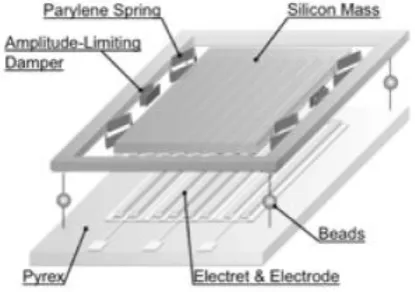
[image:5.595.324.532.539.685.2] [image:5.595.65.270.568.736.2]long and thin springs difficult to obtain by using silicon technologies. Therefore to reduce resonant frequency of VEH keeping small dimension solutions as parylene spring [35] were developed. Naurse has already using microballs that such a system could operate at very low frequencies (<2 Hz) and could produce up to 40 μW [36].
Table 1: An overview of electrostatic VEH for electret free
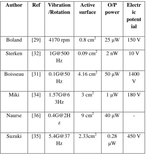
Table 2: An overview of electrostatic VEH for electret based
5.
CONCLUSION
There are three main approaches that can be used to implement a vibration to energy generator. All of the three technologies described in this review has their own pros and cons and these are now summarized. Piezoelectric offer the
simplest approach. The structural vibrations are directly converted into a voltage output by using an electrode piezoelectric material. These types of generators are the simplest type to fabricate and can be used in force and impact coupled harvesting applications. One of the major advantages is that piezoelectric transduction principle is particularly well suited to micro engineering. This method is capable of producing relatively high output voltages but only at low electrical currents. Electromagnetic generators are well-established technique of electrical power generation and the effect has been used for many years in a variety of electrical generators. The spring/mass configurations that can be used with various types of material those are well suited and proven in cyclically stressed applications. The electrostatic generator concept is easily realizable as a micro electro mechanical system and much processing know-how exists on the realization of in plane and out of plane capacitors. The electrostatic generators require an initial polarizing voltage or charge. Electrostatic generators can utilize electrets to provide the initial charge and these are capable of storing charge for many years. The output impedance of the devices is often very high and this makes them less suitable as a power supply. The three main techniques of harvesting energy from ambient vibrations have been shown to be capable of generating output power levels in the range of μW to mW.
Vibration-powered wireless sensor systems can be used in numerous scenarios and several research groups across the world are addressing possible uses in ambient intelligence, medical implants and smart clothing. Wireless, battery-less industrial condition monitoring systems are already close to commercialization.
6.
REFERENCES
[1] Gieras J F, Oh J H, Huzmezan M and Sane H S 2007 Electromechanical energy harvesting system Patent Publication Numbers WO200707002(A2), W2007070022(A3.)
[2] Wu X, Lin J, Kato S, Zhang K, Ren T and Liu L 2008 A frequency adjustable vibration energy harvester Power MEMS 2008 + microEMS2008 (Sendai) pp 245–8
[3] Roundy S and Zhang Y 2005 Toward self-tuning adaptive vibration based micro-generators Proc. SPIE—Int. Soc.Opt Eng. 5649 373–84
[4] Remtema T and Lin L 2001 Active frequency tuning for micro resonators by localized thermal
[5] Challa V R, Prasad M G, Shi Y and Fisher F T 2008 A vibration energy harvesting device with bidirectional resonance frequency tunability Smart Mater. Struct. 17015035
[6] Marzencki M, DefosseuxM and Basrour S 2009 MEMS Vibration energy harvesting devices with passive resonance frequency adaptation capability J. Intell. Mater. Syst. Struct. 18 1444–53
[7] Williams C B, Shearwood C, Harrdine M A, Mellor P H, Birch T S and Yates R B 2001 Development of an electromagnetic micro-generator IEE Proc. Circuits Devices Syst. 148 337–42
[8] Williams C W and Yates R B 1996 Analysis of a micro- electric generator for microsystems Sensor Actuators A 52 8–11
[9] Shearwood C and Yates R B 1997 Development of an electromagnetic micro-generator Electron. Lett 33 1883–4
Author Tashiro Roundy Despesse
Ref [26] [27] [28]
O/P power 36 μW 11 μW 1050 μW
Surface - 100 mm2 1800 mm2
Volume 15000
mm3
100 mm3 1800 mm3
Vibration 1.2G@6 Hz
0.23G@ 100Hz
0.3G@50hz
Polarization Voltage
45V - 3 V
Author Ref Vibration
/Rotation
Active surface
O/P power
Electr ic potent
ial
Boland [29] 4170 rpm 0.8 cm2 25 μW 150 V
Sterken [32] 1G@500 Hz
0.09 cm2 2 nW 10 V
Boisseau [31] 0.1G@50 Hz
4.16 cm2 50 μW 1400 V
Miki [34] 1.57G@6 3Hz
3 cm2 1 μW 180 V
Naurse [36] 0.4G@2H z
9 cm2 40 μW -
Suzuki [35] 5.4G@37 Hz
2.33cm2 0.28 μW
[image:6.595.48.290.427.684.2][10] Mizuno M and Chetwynd D 2003 Investigation of a resonance microgenerator J. Micromech. Microeng. 13 209–16
[11] Huang W S, Tzeng K E, Cheng M C and Huang R S 2003 Design and fabrication of a vibrational micro- generator for wearable MEMS Proc. Eurosensors XVII (Guimaraes, Portugal) pp 695–7
[12] Serre C, Fondevilla N, Cereceda C, Morante J R, Esteve J and Montserrat J 2005 Design of electromagnetic inertial generators for energy scavenging applications Proc. Eurosensors XIX (Barcelona, Spain) paper MC5 [13] Beeby S P, Tudor M J, Koukharenko E, White N M, O’Donnell T, Saha C, Kulkarni S and Roy S 2005 Micromachined silicon generator for harvesting power from vibration Proc. Transducers 2005 (Seoul, Korea) pp 780–3
[14] El-Hami M, Glynne-Jones P, James E, Beeby S P, White N M, Brown A D, Ross J N and Hill M 2001 Design and fabrication of a new vibration-based electromechanical power generator Sensors Actuators A 92 335–42
[15] The micro generating system for a watch, KINTERON http://www.kinetron.nl/cms/publish/content/download document.asp
[16] Vibration based energy harvester assessment kit. www.perpetuum.co.uk
[17] A.Vasquez Quintero,D Briand,P.Janphuang,J.J Raun, R. Lockhart,N.F. de Rooji, “Vibration Energy Harvesters on plastic foil by lamination of PZT thick sheets”, IEEE,MEMS2012,Pans,France,978 1467303255/12,2012 [18] Ahmed Telba, Wahied G.Ali, “Modeling and simulation of piezoelectric energy harvesting”, proc. Of the World Congress on engineering2012, Vol II, Londan, UK, ISBN: 978-988-19252-1-3,2012
[19] Gaudara Ravi Prakash, K.M Vinayaka Swamy,B.G. Sheerparamatti, “Simulation of nuclear radiation based Energy Harvesting Device using Piezoelectric Transducer”, Proc. Of 2011 COMSOL Conference in banglore
[20]Suyog N jagtap, Roy Paily, “Geometry optimization of a MEMS based energy harvesting device”, proc. Of IEEE students’ Technology symposium, IIT Kharagpur, TS11 MEMS01171, 2011
[21] Chengliang Sun, Ian Shi,Xudong Wang, “Fundamental study of Mechanical Energy Harvesting using Piezoelectric Nanostructures”, Journal of Applied Physics 108,034309,2010
[22] M.Guizzetti, V.Ferrari, D.Marioli, T.Zawada, “Thickness optimization of a Piezoelectric Converter for Energy Harvesting”, Proc. Of COMSOL Conference Milan, 2009
[23] Sebastian Pobering, Norbert Schwesinger, “Power supply for Wireless Sensor System”, IEEE SENSORS 2008 Conference, 1-4244-2581-5/08,2008
[24] Henry A.Sodano,Daniel J. Inman,Gyauhae park, “A Review of Power Harvesting from Vibration using piezoelectric material”, The Shock and Vibration Digest, Vol. 36, N0.3,197-205,2004
[25] Meninger S, Mur-Miranda J O, Amirtharajah R, Chandrakasan A, Lang J. Vibration-to-electric energy conversion. IEEE transactions on very large scale integration (VLSI) 2011;9(1): 64-75.
[26] Tashiro R, Kabei N, Katayama K, Tsuboi E, Tsuchiya K. Development of an electrostatic generator for a cardiac pacemaker that harnesses the ventricular wall motion. Journal of Artificial Organs 2002;5:239- 45.
[27] Roundy S. Energy Scavenging for Wireless Sensor Nodes with a Focus on Vibration to Electricity Conversion. PhD Thesis. University of California, Berkeley, 2003.
[28] Despesse G, Chaillout J J, Jager T, Léger J M, Vassilev A,Basrour S, Charlot B. High damping electrostatic system for vibration energy scavenging. Proc. sOc- EUSAI 2005:283-6.
[29] Boland J, Chao Y, Suzuki Y, Tai Y. Micro electret power generator. Proc. MEMS 2003:538-41.
[30] Mizuno M, Chetwynd D. Investigation of a resonance microgenerator. IOP Journal of micromechanics and Microengineering 2003; 13: 209-16 http://dx.doi.org/ 10.1088/0960-1317/13/2/307
[31] Boisseau S, Despesse G, Ricart T, Defay E, Sylvestre A. Cantilever-based electret energy harvesters. IOP Smart Materials and Structures 2011; 20(105013). http://dx.doi.org/10.1088/0964-1726/20/10/105013 [32] Sterken T, Fiorini P, Altena G, Van Hoof C, Puers R. Harvesting Energy from Vibrations by a Micromachined Electret Generator. Proc. Transducers 2007: 129-32. [33] Tsutsumino T, Suzuki Y, Kasagi N, Sakane Y. Seismic Power Generator Using High-Performance Polymer Electret. Proc. MEMS 2006: 98-101.
[34] Miki D, Honzumi M, Suzuki S, Kasagi N. Large- amplitude MEMS electret generator with nonlinear spring. Proc. MEMS 2010: 176-9.
[35] Suzuki Y, Edamoto M, Kasagi N, Kashwagi K, Morizawa Y. Micro electret energy harvesting device with analogue impedance conversion circuit. Proc. PowerMEMS 2008: 7-10.
![Figure 2. Inertial generator described by Serre C et al [12].](https://thumb-us.123doks.com/thumbv2/123dok_us/8079924.781994/2.595.329.520.359.511/figure-inertial-generator-described-serre-c-et-al.webp)
![Figure 4. The electromagnetic generator proposed by El-Hami et al [14].](https://thumb-us.123doks.com/thumbv2/123dok_us/8079924.781994/3.595.60.281.74.188/figure-electromagnetic-generator-proposed-el-hami-et-al.webp)