THE STABILITY OF LIQUID CRYSTAL PRETILT ANGLE ON ION BEAM
IRRADIATED AMORPHOUS CARBON FILMS DEPENDING ON AIR
EXPOSING SEQUENCE AND SURFACE CLEANING METHOD
Jongbok Kim
Department of Materials Science and Engineering, Kumoh National Institute of Technology, Daehak-ro 61, Gumi, Korea E-Mail: [email protected]
ABSTRACT
Ion beam (IB) irradiation to align liquid crystal (LC) molecules has attracted a lot of interest as an alternative of mechanical rubbing method due to its noncontact processing property. However, it suffers from degradation problem which is to decrease pretilt angle with air exposure. Here, the stability of pretilt angle depending on air exposing sequence and surface cleaning method using IB irradiated amorphous carbon films with and without hydrogen were studied. Specifically, two different air exposing sequences were adopted. Amorphous carbon alignment layers were exposed to the air before or after IB irradiation, followed by assembling LC cells. Then, their pretilt angles were measured by crystal rotation method. When exposing alignment layers to the air before IB irradiation, the pretilt angle was similar regardless of air exposure. However, exposing alignment layers after IB irradiation resulted in severe decrease of pretilt angle. It indicated that dangling bonds generated during IB irradiation on alignment layers are main source for pretilt angle degradation in IB irradiation method. Then, I introduced two different cleaning methods, sonication and rinsing with deionized (DI) water. When cleaning IB irradiated amorphous carbon surfaces via sonication, it induced the degradation of pretilt angle. However, rinsing method on hydrogenated amorphous carbon films did not affect the pretilt angle of LC molecules.
Keywords: liquid crystal, ion beam irradiation method, pretilt angle, amorphous carbon.
INTRODUCTION
These days, liquid crystal displays (LCD) are the most popular display among several display devices such as cathode ray tube (CRT), organic light emitting device (OLED), plasma display panel (PDP) and field emission display (FED). In order to express a uniform image in LCD, it is essential to align liquid crystal (LC) molecules along one direction. Such alignment process is usually achieved by mechanical rubbing (Yang et al., 2006 and Stohr et al., 1999). Specifically, in order to get uniform alignment of LC molecules in macroscopic scale, rubbing clothes mechanically scrub polymer alignment layer, which generates physical and chemical surface anisotropies in rubbing method. Then, these anisotropies assign the driving force to LC molecules for unidirectional alignment along rubbing direction and result in macroscopically uniform LC alignment. However, physical contact between rubbing clothes and alignment layer generates dust particles and induces electrostatic charge problem (Kim et al., 2008). To overcome these problems, people suggest ion beam (IB) irradiation method on inorganic alignment layers (Doyle et al., 2003; Chaudhari et al., 2001; Kim et al., 2007 and Lee et al., 2013). In IB irradiation, various IBs such as argon (Ar) IB and hydrogen (H2) IB are irradiated on several alignment layers. Then, because IB selectively destroys chemical
IB irradiation direction and resulting in chemical anisotropy. Then, such chemical anisotropy aligns LC molecules along IB irradiation direction, achieving uniform LC alignment in macroscopic scale (Kim et al., 2007; Ahn et al., 2007; Kim et al., 2007 and Ahn et al., 2007). However, while IB irradiation method on inorganic alignment layers does not generate dust particles and electrostatic charge problem, it suffers from pretilt angle degradation with air exposure. In other words, pretilt angle is gradually decreasing with air exposing time.
amorphous carbon films can maintain its pretilt angle. Thus, rinsing with DI water is a proper method for the cleaning of alignment layer in IB irradiation method.
EXPERIMENTAL METHODS
To construct LC cells, I used ITO glass as a transparent conductive substrate. ITO glass was first cleaned with trichloroethylene (TCE), acetone, and isopropyl alcohol for 10 min by sonication. After drying ITO substrate by nitrogen gas, amorphous carbon film as alignment layer was deposited on ITO glass by RF magnetron sputter with graphite target (99.9999%). Figure 1 shows RF magnetron sputtering system. RF magnetron sputtering system adopted Ar gas to deposit amorphous carbon films or the mixture of Ar and H2 gas to deposit hydrogenated amorphous carbon films. When adopting the mixture gas, the ratio between H2 and Ar [RH2=PH2/(PAr+PH2)] was 26%. The base pressure and working pressure was 3 x 10⁻⁶ Torr and 5 x 10⁻³ Torr, respectively. RF power to deposit amorphous carbon films with and without hydrogen was fixed at 100 W. The final thickness of amorphous carbon and hydrogenated amorphous carbon films was about 10 nm.
Figure-1. Dual magnetron RF sputtering system to deposit amorphous carbon alignment layers with and without
hydrogen (Ahn, 2007).
Then, amorphous carbon and hydrogenated amorphous carbon films were irradiated by Ar IB. Figure-2 represents IB irradiation system to get uniform LC alignment. IB energy was 200 eV and IB irradiation angle was 45o. Finally, antiparallel cells were fabricated with IB irradiated alignment layers. Cell gap was fixed to 50 um and pretilt angle was measured via crystal rotation method.
Figure-2. IB irradiation system to get uniform LC alignment. In this system, Air ions accelerated through two grids. Then, they are irradiated on various alignment
layers. (Ahn 2007).
LC cells were classified into 3 groups (reference, group A and group B). In case of reference, LC cells were assembled right after film deposition and IB irradiation without time delay between the processes, followed by measuring pretilt angle. Group A and B were exposed to the air for 10 days in a difference sequence before constructing LC cells. Specifically, amorphous carbon films with and without hydrogen were exposed to the air before IB irradiation in group A. Then, alignment layers were irradiated by IB and LC cells were fabricated. In group B, alignment layers were irradiated by IB and then exposed to the air for 10 days. Then, LC cells were constructed. After measuring pretilt angle via crystal rotation method, the pretilt angle of group A and group B was finally compared with that of reference cell.
Then, in order to test the stability of pretilt angle in surface cleaning, I adopted two difference cleaning method, ultra-sonication and rinsing with DI water. Specifically, amorphous carbon alignment layers were irradiated by IB and then were cleaned by ultra-sonication or rinsing. After drying them by nitrogen, antiparallel cells were assembled, followed by measuring pretilt angle. Then, the pretilt angle was compared with that of LC cell without cleaning process.
Figure-3. LC pretilt angle of reference cell and group A (LC cells constructed 10 days after air exposure of alignment layers without IB irradiation. Amorphous carbon and hydrogenated amorphous carbon films were
adopted as alignment layers).
Figure-3 shows the pretilt angle of reference and group A (group A was constructed 10 days after air exposure of alignment layer without IB irradiation). First, when adopting amorphous carbon film as an alignment layer (left in Figure-3), the pretilt angle of the reference cell was 6.3o. Group A also showed comparable pretilt angle, which was 6.9o. When using hydrogenated amorphous carbon film instead of amorphous carbon alignment layer without hydrogen (right in Fig. 3), it also represented similar result. Reference and group A showed the pretilt angle of 4.4o and 3.9o, respectively. Because group A is the cells exposed to the air before IB irradiation, it indicates the air exposure prior to IB irradiation does not much affect the pretilt angle of LC cells regardless of adopting amorphous carbon film or hydrogenated amorphous carbon film as an alignment layer.
On the contrary, the exposure of alignment layers into the air after IB irradiation significantly changed the pretilt angle of LC cells. Figure-4 shows the pretilt angle of reference and group B (group B was assembled 10 days after air exposure of alignment layer with IB irradiation). When using amorphous carbon film as an alignment layer (left in Figure-4), the pretilt angle was 6.3o in reference and 3.5o in group B. The pretilt angle dropped more than 40% in group B, which resulted from air exposure of IB irradiated alignment layer. Hydrogenated amorphous carbon film also represented same trend. While reference showed pretilt angle of 4.4o, hydrogenated amorphous carbon film exposed to air after IB irradiation represented the pretilt angle of 1.7o (right in Figure-4). It was only about 40% of reference. Thus, I knew that while alignment layers can wait quite a while for IB irradiation in LCD manufacturing process, IB irradiated alignment layers should be assembled right after IB irradiation without the air exposure due to instability of IB irradiated alignment layer in air.
Figure-5. Dispersion, polar and total surface energy of amorphous carbon film irradiated by IB depending on air exposure time. They were calculated from the contact angle of water and diiodomethane.
contact angle of alignment layer right after IB irradiation, dispersion and polar surface energy were 35 mJ/m2 and 22 mJ/m2, respectively, indicating total surface energy of 57 mJ/m2. But, air exposure changed both dispersion and polar surface energy. In case of polar energy, it dropped to 8.7 mJ/m2 in 5 days and 7.7 mJ/m2 in 10 days. However, air exposure increased dispersion energy from 35 mJ/m2 to 36.8 mJ/m2 in 5 days and 37.2 mJ/m2 in 10 days. Because dispersion energy is important to decide the interaction between LC molecules and alignment layer, increasing dispersion energy indicates van der Waals interaction between LC and alignment layer becomes stronger with air exposure. Thus, I concluded that air exposure makes van der Waals interaction between LC and alignment layer be strong, decreasing pretilt angle with air exposure of IB irradiated amorphous carbon films.
Figure-6. Relative pretilt angle depending on surface cleaning method and time in LC cells with amorphous
carbon alignment layers.
[image:4.612.79.291.284.438.2]Then, two cleaning approaches, ultra-sonication and rinsing with DI water, were tested to find proper cleaning tool without pretilt angle degradation for IB irradiation method. To introduce IB irradiation method into the industry and replace mechanical rubbing method for uniform LC alignment, cleaning process is necessary after IB irradiation process because alignment layers should be moved to assembly line after IB irradiation and dust particle can be attached during the line transfer. To test stability on surface cleaning, amorphous carbon films and hydrogenated amorphous carbon films were irradiated by Ar IB, following sonication or rinsing using DI water and then measuring pretilt angle. Finally, their pretilt angles were compared to that of LC cell which was constructed without cleaning prcess of alignment layer.
Figure-7. Relative pretilt angle depending on surface cleaning method and time in LC cells constructed with
hydrogenated amorphous carbon alignment layers.
Figure 6 and 7 shows relative pretilt angle of LC cells adopting amorphous carbon films and hydrogenated amorphous carbon films as alignment layers depending on cleaning process and time. First, when using amorphous carbon film as an alignment layer, ultra-sonication decreased its pretilt angle by 24% after 1 min cleaning and 42% after 5 min cleaning. However, cleaning IB irradiated amorphous carbon film by rinsing maintained the pretilt angle more than 80%. In hydrogenated amorphous carbon alignment layers, ultra-sonication showed similar results with amorphous carbon films without hydrogen. Ultra-sonication for 1 min and 5 min decreased pretilt angle by 20% and 51%, respectively. But, rinsing hydrogenated amorphous carbon films did not affect the pretilt angle, maintaining its original pretilt angle. Therefore, it indicates that rinsing hydrogenated amorphous carbon films is the best to introduce IB irradiation method into industry line for LCD manufacturing.
Figure-8. Relative pretilt angle depending on surface cleaning method and time in LC cells constructed with
hydrogenated amorphous carbon alignment layers.
0 1 2 3 4 5
0 20 40 60 80 100
Rel
ati
ve Tr
ans
mi
tt
ance
(
%
)
Driving voltage (V)
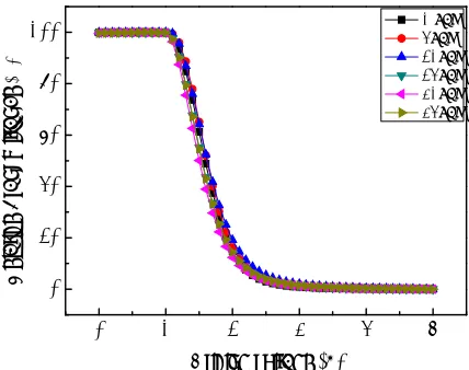
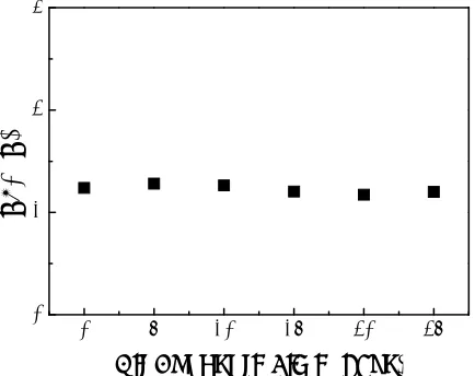
[image:4.612.321.535.518.687.2]Figure-9. V10 of LC cell depending on air exposing time. V10 means the applied voltage to make relative
transmittance be 10% in LC cell.
Finally, in order to test driving stability of such LC cells with hydrogenated amorphous carbon alignment layer in air, voltage-transmittance (V-T) property was measured depending on air exposure time of LC cells. Figure 8 shows V-T curve of LC cell in accordance to air exposure time. When macroscopically examining V-T curve, they are almost overlapped and looked very similar to each other. In order quantitatively to analyse V-T curve, I extracted V10 and V90 in each V-T curve (V10 and V90 are the voltage when relative transmittance is 10% and 90% in V-T curve, respectively) and represented them in Figure-9 and 10. In case of V90 (Figure-9), LC cell initially showed V90 of 2.117 V. When exposing LC cell into the air, it was 2.154 V in 5 days, 2.249 V in 10 days, 2.115 V in 15 days, 2.075 V in 20 days and 2.136 V in 25 days, respectively. Thus, we knew that V90 is very stable regardless of air exposure.
V10 represents similar results to V90 (Figure 10). When measuring V-T curve right after LC cell assembly without air exposure, V10 was 1.240 V. Then, when exposing LC cell into the air, it was 1.282 V in 5 days, 1.264 V in 10 days, 1.204 V in 15 days, 1.172 V in 20 days and 1.201 V in 25 days, respectively. Therefore, we can conclude that LC cell with hydrogenated amorphous carbon alignment layer shows stable V-T characteristics in IB irradiation method.
CONCLUSIONS
I studied the pretilt angle stability depending on air exposure sequences and surface cleaning methods. While exposing to the air after IB irradiation dramatically decreased pretilt angle regardless of amorphous carbon and hydrogenated amorphous carbon alignment layers, air exposure before IB irradiation did not much change the pretilt angle in both films. It indicates dangling bond generated during IB irradiation process is a main cause to decrease the pretilt angle during air exposure. Also, ultra-sonication on IB irradiated alignment layer resulted in the decrease of pretilt angle. However, adopting rising method with hydrogenated amorphous carbon films as a cleaning method for IB irradiation maintained its pretilt angle. Thus, I conclude rinsing hydrogenated amorphous carbon film is proper cleaning method for introducing IB irradiation method into LCD industry.
ACKNOWLEDGEMENTS
This paper was supported by Research Fund, Kumoh National Institute of Technology.
REFERENCES
Yang D. -K. and Wu S. -T. 2006. Fundamentals of liquid crystal devices, John Wiley and Sons, Ltd. pp. 34-35.
Stohr J. and Samant M. G. 1999. Liquid crystal alignment by rubbed polymer surfaces: a microscopic bond orientation model. Journal of Electron Spectroscopy and Related Phenomena. 98-99, pp. 189-207
Kim J. B., Lim J. R., Park J. S., Ahn H. J., Lee M. J., Jo S. J., Kim M., Kang D., Lee. S. J., Kim Y. S. and Baik H. K. 2008. The directional peeling effect of nanostructured rigiflex molds on liquid crystal devices: liquid crystal alignment and optical properties. Advanced Functional Materials. 18, pp. 1340-1347.
Doyle J. P., Chaudhari P., Lacey J. L., Galligan E. A., Lien S. C., Callegari A. C., Lang N. D., Lu M., Nakagawa Y., Nakano H., Okazaki N., Odahara S., Katoh Y., Saitoh
0 5 10 15 20 25
1 2 3 4
V10 (
V
)
Air Exposure Time
0 5 10 15 20 25
0 1 2 3
[image:5.612.79.296.520.692.2]Chaudhari P., Lacey J., Doyle J., Galligan E., Lien S. C. A., Callegari A., Hougham G., Lang N. D., Andry P. S., John R., Yang K. H., Lu M., Cai C., Speidell J., Purushothaman S., Ritsko J., Samant M., Stohr J., Nakagawa Y., Katoh Y., Saitoh Y., Sakai K., Satoh H., Odahara S., Nakano H., Nakagaki J. and Shiota Y. 2001. Atomic beam alignment of inorganic materials for liquid crystal displays. Nature. 411, pp. 56-59.
Kim K. C., Ahn H. J., Kim J. B., Hwang B. H., Kim J. T. and Baik H. K. 2007. Pretilt angle control of crabon incorporated amorphous silicon oxide treated by ion beam irradiation. Materials Chemistry and Physics. 106, pp. 54-57.
Lee J. –J., Park H. –G., Han J. –J., Kim. D. –H. and Seo, D. -S. 2013. Surface reformation on soluion-derived zinc oxide films for liquid crystl systems via ion-beam irradiation. Journal of Materials Chemistry C. 1, pp. 6824-6828.
Kim J. B., Kim K. C., Ahn H. J., Hwang B. H., Hyun D. C., Kim J. T., Lee S. J. and Baik H. K. 2007. Appropriate hydrogen-incorporated diamond-like carbon film for application to liquid crystal display. Japanese Journal of Applied Physics. 46 8A, pp. 5213-5217.
Ahn H. J., Kim K. C., Kim J. B. and Hwang B. H. 2007. Various liquid crystal alignments on fluorinated diamond-like carbon layer by ion beam treatment. Japanese Journal of Applied Physics. 46 6A, pp. 3521-3523.
Kim J. B., Kim K. C., Ahn H. J., Hwang B. H., Hyun D. C. and Baik H. K. 2007. Variable liquid crystal pretilt angles on various compositions of alignment layers. Applied Physics Letters. 90, pp. 043515.
Ahn H. J., Kim J. B., Kim K. C., Hwang B. H., Kim J. T., Baik H. K., Park J. S. and Kang D. 2007. Liquid crystal pretilt angle control using adjustable wetting properties of alignment layers. Applied Physics Letters. 90, pp. 253505.