www.ijsrp.org
Gesture Actuated Robotic Arm
AAKASH K. SANCHETI
B.E. - E&TCMMCOE (2011-12) UNIVERSITY OF PUNE
PUNE, INDIA [email protected]
Abstract-The idea is to change the perception of remote controls for actuating manually operated Robotic-Arm. Well, this paper presents a thought and a way to eradicate the buttons, joysticks and replace them with some other more intuitive technique, that is, controlling the complete Robotic Arm by the operators hand movement or motion or gesture. In this paper the completely electronic (i.e. without mechanical sensors) way of achieving the above stated goal is discussed. This is achieved by using MEMS-ACCELEROMETER technology (that is used in smart phones for tilt sensing), showing the diversity of the application of the same technology.
Index Terms- 6-DOF, MEMS, MEMS Accelerometer, g - force, 3axis, Co-ordinate acceleration, Static and Dynamic acceleration, potentiometer, ARM controller, ESD, loading effects (less current sourcing), RTOS.
INTRODUCTION
The breakthrough technological revolutions that changed the dimensions of the perception of manufacturing in the industry took place due to ROBOTIC-ARM. Traditionally and currently these Arms or machines are controlled either by preloaded code (i.e. automatic) or via Joystick ( i.e. Manual).
Now in industries or anywhere else minimum the Robotic-Arm with 5DOF and a Gripper is required. So in all 6motors or actuators are required to drive it. And hence this calls for the need of (in case of manually operated) joystick or remote control that has 5 to 6 keys to control and actuate the individual motions/ motors of robotic arm respectively. Practically thinking simultaneously using 6keys and using them by analyzing the motion of robotic arm in 3D requires rigorous practice and judgment. That is the system is very less intuitive and this is the knack of the article, that is, to develop the system that would make the existing system more intuitive and user friendly.
Rather than hunting for some other kind of ‘Soft-keys’ etc I just thought of utilizing the super-natural power of human i.e. to ‘move our hands’. So the system discussed in the paper is to control the motion of Robotic-Arm by mere movements of human arm eradicating the species of keys and joysticks.
So the aim of the paper can be briefed as “designing the system, the sensory part, which can be mounted on the human
(rather operators) arm, synthesize the signals and ultimately generate the signals to actuate the Robotic Arm” and hence to
Replicate the motion of the human arm. SENSORS
Different types of sensors are available like piezoelectric, capacitive etc that can be used to sense the movement. But the key problem with these sensors is that they generate the signals of single axis (ref: [9]) whereas in real practical world we require 3D motions to perform even the most trivial task. So taking into account all considerations the MEMS (Micro Electro Mechanical Systems) motion sensor was selected. Basically the MEMS-ACCELEROMETER is selected as it provides the 3axis – X, Y, Z signals depending upon the angular position of the sensor.
OVERVIEW OF MEMS -ACCELEROMETER
Basically, an Accelerometer is a device that measures the proper acceleration. This is not the same as the coordinate acceleration (change of velocity with respect to time), but is rather the type of acceleration associated with the phenomenon of weight experienced by a test body / mass that resides in the frame of reference of the accelerometer device. For an example, an accelerometer will measure a value when sitting on the ground, because masses there have weights, even though they do not change velocity.
An accelerometer thus measures weight per unit of (test) mass, a quantity also known as specific force or g-force. These sensors are basically used in the Smart Phones for tilt sensing applications. MEMS – ACCELEROMETER provides the 3axis analog signals(X, Y, Z) corresponding to its position and applied g-force (as shown in table-1). Its features are:
Low Current / Power Consumption
Low operating voltage MEMS are available.
High Sensitivity
Static and Dynamic acceleration.
Robust Design, High Shocks Survivability.
www.ijsrp.org Figure 1: Proposed Block Diagram
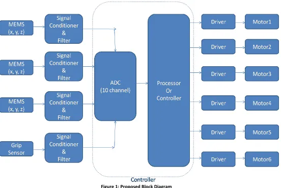
PROPOSED FUNCTIONAL DIAGRAM
Here the flow of signals and activity is given. In the later section the comprehensive study and selection of each individual block is described.
Input section (Sensory part)
Sensors:
Here, MEMS-Accelerometer sensors are used for detecting the motion of the human arm. As the human arm has 3major joints (Shoulder, Elbow and Wrist) the normally used robotic arm also has nearly the same kind of structure, so for detecting the motion of each joint a individual or separate sensor is required. Hence 3 sensors are required as shown in figure1 (placement of sensors is discussed later in section 6 and shown in figure3 in this paper).
Gripping sensor:
Here the sensor can be the simple linear potentiometer (variable resistor with rotary shaft). Means the plates or rods can be connected at one end such that the joint acts as the axis like that of hands of clock (as shown in figure 2). And then the shaft of potentiometer should be connected to this joint such that the shaft acts as the axis.
[image:2.612.346.540.524.706.2]Now the plates can be placed on the fingers of the human fingers. So now when the operator moves the fingers the plates would move in angular way and hence the shaft of potentiometer rotates. Therefore we can say that this sense’s the position of the human finger (grip action) and hence accordingly generate the equivalent signal to be given to the controller. Controller then actuates the Motor 6 (grip motor) of the robotic arm.
www.ijsrp.org Signal Conditioner:
Basically, MEMS-Accelerometers have low load driving capacity and also the signal may eventually deteriorate and ultimately result in wrong interpretation by the controller.
So the proper signal conditioning is required for avoiding loading effects on sensor and then filter is used for avoiding high frequency external noise interruption.
Analog to Digital Convertor Section
The output of all the sensors will be in analog form so it needs to be digitized for processing and working upon by the processor.
Controller Section
The controller is the main brain of the system. Its main function is processing the data and thus taking decisions as per pre-stored or predefined code or algorithm.
The data received from the MEMS through ADC (i.e. digital equivalent) will be processed by the controller for taking the desired actions. It would be better choice to choose the controller having built-in ADC as it would minimize the external hardware requirement
Thus according to the signal and algorithm the brain would generate the actuating signals for driving the motors of the Arm.
Output section (Robotic Arm end)
Driver:
The controller provides low voltage and low current signal which cannot be used to drive the motor, so this calls for the need of motor driver.
Motor driver will take signal from controller and will provide the same to the motor but in the boosted or amplified form.
Motors:
Motors are required for achieving the movement of Robotic arm. For providing 5-DOF motion 5 motors are used whose configuration is as follows:
Motor1 & Motor2 : Shoulder Motion. Motor 3 : Elbow Motion. Motor 4 & Motor 5 : Wrist Motion. Motor 6 : Gripping Motion.
The selection of the motors and design of robotic-arm is out of scope of this paper. Mostly the robotic arms use Servo motors for actuation due to its combined advantage of accuracy, precision and torque over normal DC/AC motors and stepper motors.
SELECTION Sensor:
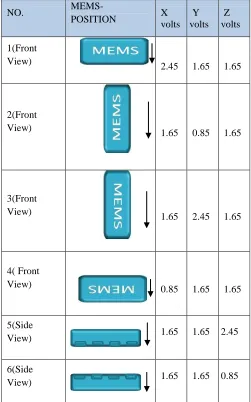
[image:3.612.319.570.58.460.2]The sensor as alleged above is MEMS-Accelerometer. It has 6 different signals for respective angular positions of the sensor as shown in table1.
Table 1: Output voltages with respect to MEMS Position ( - indicates the direction of Earth’s gravity)
NO. MEMS-
POSITION X volts Y volts Z volts 1(Front
View) 2.45 1.65 1.65
2(Front View)
1.65 0.85 1.65
3(Front View)
1.65 2.45 1.65
4( Front View)
0.85 1.65 1.65
5(Side View)
1.65 1.65 2.45
6(Side View)
1.65 1.65 0.85
Thus here in the system according to the angular position or data given by the sensor the exact angle of operators arm would be judged and calculated. And then from this obtained data and the pre-defined values, the look up tables and through the algorithm the position of the operators arm would be converted into digital form in binary language.
The final signal on tilt of 90degrees in all axis is shown in table1. The sensor actually is linear in nature and hence the change in voltage/signal per degree can be mathematically calculated and practically observed.
MEMS can actually provide the accuracy of 1degree tilt which is
= 800mV/90 Change in Volts / degree tilt = 8.88 or 9 mV.
Analog to Digital Converter (ADC): The specifications of the ADC to be used are:
1. Resolution:
www.ijsrp.org
From the table 1 it can be seen that for 90degrees the change in signal is of approx. 800mV.
So practically considering the accuracy of 2degrees change in the hand movement the min. change in the input to be sensed = 18mV.
So from the formula
Min. Voltage change sensed = Vref / (2^n - 1). Where
n : no. of bits. Assuming Vref= 3.3V Therefore we get ‘n >= 8’.
2. ADC Type:
Here the ADC should be such that it is accurate as well as conversion time is less. So considering both the factors the ADC that can be used is Successive Approximation type ADC.
As S.A. ADC has quite good accuracy and also the conversion time is less around 200ns.
We require 10ADC lines (3for each MEMS * 3MEMS + 1 for grip sensor) so the total conversion time would be: Total Conversion time = 200n * 10
= 2000nS or 2mS
Motor Driver:
As discussed previously the motors used are servo motors. Now the servos require the PWM signal to actuate. So the driver should be actually PWM timing signal generator. The PWM signal standard timings are
Total Time (T) = 20ms.
On Time (Ton) = 1ms (for shaft pos. 0degrees). On Time (Ton) = 2ms (Shaft pos.180degrees).
The timing for any angle position can be calculated simply as the angle of rotation and timing are linearly proportional.
Controller:
The controller selected should be fast enough and should respond or perform operations in real-time. Here the controller does sinking the input data, processing it and running the pre-defined algorithm stored in memory and accordingly provides the signals to the outside world. This is very basic requirement and the system has a dedicated and specific task. So a controller that satisfies the basic requirement as well as have the desired peripherals like ADC (>8bit) and PWM generator can be used.
Therefore along with the high speed, real time operation, built-in peripheral the requirement of controller is that it should have at least 10-ADC channels (>8bit each) and 6-PWM signals (individually controlled) as per the requirements alleged above. So the ARM7 core based controller is selected as it has
1. 10channel- 10bit SA type ADC
2. PWM-6Channels with individual control. 3. Upto 60MHz clock frequency.
And also it has advantages of internal PLL to multiply the oscillator frequency and also the RTOS portability is available on it because if in future the memory management or other complicated tasks or processes are required for operation of structure then it necessitates porting RTOS (Real Time Operating System) on the controller.
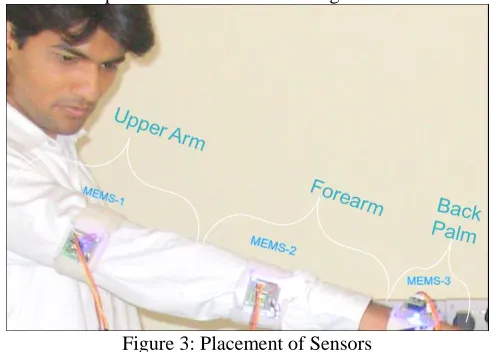
PLACEMENT OF SENSORS
[image:4.612.321.569.186.362.2]The g-force sensors or accelerometers are to be mounted on the human or operators hand as shown in figure 2.
Figure 3: Placement of Sensors Placement of sensors and its replicating part:
MEMS-1 is placed on the upper arm of hand which will control motors - Motor 1 & Motor 2 i.e. 2 - shoulder motors.
MEMS-2 is placed on the forearm of hand which is used to control the Motor 3 (Elbow motor).
MEMS-3 is placed on the back palm (backside of palm) and used to control wrist motion of artificial arm (Motor 4 and Motor 5).
Now also the consideration of the muscle and skin movement of the operator has to be taken into account.
E.g. when we do the roll motion of the wrist (rotational movement) the fully or partially forearm also rotates and so the sensor placed on forearm (MEMS-2) may also rotate and hence the signal may change leading lead to wrong interpretation by controller and hence wrong action of robotic arm.
www.ijsrp.org
TEST RESULTS Sensor:
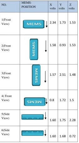
[image:5.612.44.296.175.632.2]The sensor as alleged above is MEMS-Accelerometer. It has 6 different signals for respective angular positions of the sensor as shown in table1.
Table 2: Practically Observed Output voltages with respect to MEMS Position ( - indicates the direction of Earth’s gravity)
NO. MEMS-
POSITION X volts volts Y volts Z
1(Front View)
2.34
1.73
1.53
2(Front View)
1.58
0.93
1.53
3(Front View)
1.57
2.51
1.48
4( Front View)
0.8
1.72
1.5
5(Side View)
1.60
1.75
2.28
6(Side View)
1.60
1.68
0.72
From the above practically observed results and the table1 it can be concluded that the output voltage of sensors are practically different from standard values. So in the coding or algorithm the averaging of the signals is to be done. This averaging makes the system generalized for different MEMS sensors.
Sensor loading issue
The load driving capacity of MEMS is quite low as its output current is low. Due to this the sensor needs to be placed within few centimeters from the controller.
So to overcome this loading problem the voltage follower stage needs to be introduced that provides the high input impedance and low output impedance and hence eliminates the issue of source or sensor loading.
Protection for MEMS
Basically MEMS sensors are prone to static voltages. They have the internal ESD protection of 3000-4000V but as within a human body the static charge can be generated above 25KV the mere gentle touch of our unearthed body can damage the sensor.
For protection either the ‘Anti-static wrist band ‘or ‘earthing or grounding band’ should be used at the time of designing or working over it. Also while designing circuitry special protection or shielding should be provided for the MEMS sensors.
CONCLUSION
This article is an example of the completely diverse application of the TILT-SENSING (as in case of Smart phones) in terms robotics and manufacturing sector. Here it is shown how with minimum simple hardware and intelligent software the gesture controlled technology shown in Sci-Fi movies can be implemented practically. Future works aimed is implementing the wireless protocol so that operator at one end can control the robotic arm wirelessly at the other end.
REFERENCES
[1] Richard Balogh, MEMS Sensors.
[2] MicroElectroMechanicalSystems (MEMS), START (Selected Topics in Assurance Related Technologies) , volume 8, number 1.
[3] Wong Guan Hao, Yap Yee Leck and Lim Chot Hun.“6-DOF PC-Based robotic arm (PC-roboarm) with efficient trajectory planning and speed control” 2011 4th International Conference on Mechatronics (ICOM), 17-19 May 2011, Kuala Lumpur, Malaysia.
[4] ARM system developers guide (book) by Sloss & Symes & Wright.
[5] Application Note- AN3308
www.ijsrp.org [7] Chung-Hsien Kuo, Yu-Wei Lai, Kuo-Wei Chiu, Shih-Tseng
Lee. “Motion Planning and Control of Interactive Humanoid Robotic Arms” IEEE International Conference on Advanced Robotics and its Social Impacts Taipei, Taiwan, Aug. 23-25, 2008.
[8] Kaiser, Kenneth L. (2006). Electrostatic discharge. Washington, DC: Taylor & Francis. pp. 2–73.