FPGA-BASED IMPLEMENTATION OF ELECTRONIC ABACUS USING ALTERA DE2 BOARD
AZMI BIN SIDEK
A project report submitted in partial fulfilment of the requirement for the award of the
Degree of Master of Electrical Engineering
Faculty of Electrical and Electronic Engineering Universiti Tun Hussein Onn Malaysia
iv
ACKNOWLEDGEMENT
Praise to Allah upon His blessing that granted me the guidance, strength and knowledge to complete this project.
Special appreciation to my supervisor, Assoc. Prof. Dr. Abd. Kadir bin Mahamad for the support and guidance throughout the duration of my study. Not forgetting my fellow colleagues who gave me the friendly environment to work within.
ABSTRACT
vi
ABSTRAK
TABLE OF CONTENTS
ACKNOWLEDGEMENT iv
ABSTRACT v
ABSTRAK vi
LIST OF TABLES x
LIST OF FIGURES xi
LIST OF SYMBOLS AND ABBREVIATIONS xiv
LIST OF APPENDICES xv
CHAPTER 1 1
INTRODUCTION 1
1.1 Introduction 1
1.2 Problem Statement 2
1.3 Objectives 2
1.4 Project Scope 3
1.5 The Organisation of Thesis 3
CHAPTER 2 5
LITERATURE REVIEW 5
2.1 Introduction 5
2.2 Abacus Historical Review 5
2.3 Abacus Architecture 8
2.4 Abacus Arithmetic Operation 9
viii
2.4.2 Subtraction 12
2.4.3 Multiplication 12
2.4.4 Division 14
2.5 Previous Related Works 16
2.6 Summary of Previous Related Works 18
CHAPTER 3 20
METHODOLOGY 20
3.1 Introduction 20
3.2 Project Activities 20
3.3 Hardware Design 21
3.4 Abacus Numerical Display and Arithmetic Algorithm 27
3.5 Experimental Configuration 30
CHAPTER 4 33
DATA ANALYSIS AND RESULTS 33
4.1 Introduction 33
4.2 Bead Sensor Circuitry and DE2 Interface Board Evaluation 33
4.3 Bead Sensor Decoder 37
4.4 Binary to ASCII Conversion 38
4.5 LCD Controller 39
4.6 Arithmetic Algorithm 40
4.6.1 Two Variables Arithmetic Operation 41
4.6.2 Three Variables Arithmetic Operation 42 4.6.2.1 Combinations of Additional Operators 43 4.6.2.2 Combinations of Subtraction Operators 46 4.6.2.3 Combinations of Multiplication Operators 47 4.6.2.4 Combinations of Division Operators 47
4.8 Complete System Evaluations 51
4.8.1 Display Mode 53
4.8.2 Arithmetic Mode 53
4.8.2.1 Two Variables Mode 54
4.8.2.2 Three Variables Mode 57
CHAPTER 5 67
DISCUSSION AND CONCLUSIONS 67
5.1 Introduction 67
5.2 Discussion 67
5.3 Conclusions 70
5.4 Future Works 71
REFERENCES Error! Bookmark not defined.
APPENDIX A 76
APPENDIX B 78
APPENDIX C 80
APPENDIX D 81
APPENDIX E 82
x
LIST OF TABLES
2.1 Summary of previous related works 17
4.1 Binary logical levels 32
4.2 Bead position binary representation with respect to numeral value
33
4.3 Experimental result for abacus column 7 33 4.4 Experimental result for abacus column 6 34 4.5 Experimental result for abacus column 5 34 4.6 Experimental result for abacus column 4 34 4.7 Experimental result for abacus column 3 34 4.8 Experimental result for abacus column 2 35 4.9 Experimental result for abacus column 1 35
4.10 Combinational of addition operators 42
4.11 Combinational of subtraction operators 44
4.12 Combinational of multiplication operators 45
4.13 Combinational of division operators 46
LIST OF FIGURES
2.1 Salamis Tablet 6
2.2 Replica of Roman Abacus 6
2.3 Chinese abacus (2/5 suan pan) 7
2.4 Japanese abacus (soroban) 8
2.5 The evolution of counting devices 8
2.6 Japanese abacus construction and notations 9 2.7 Japanese abacus beads position and numerical
value
9
2.8 Additional Operation 10
2.9 Subtraction Operation 12
2.10 Multiplication Operation 14
2.11 Division Operation 15
3.1 Project flowchart 20
3.2 Abacus model used in hardware design 21
3.3 Abacus modification 21
3.4 DE2Interface board 22
3.5 Bead sensor board elevation 22
3.6 Multistage board configuration with respect to abacus bead
23
3.7 Proximity sensor grid configuration on bead sensor board
23
3.8 Proximity sensorcontrol circuitry 24
3.9 Configuration of alternate column triggering 25 3.10 Configuration of I2C interconnection 26 3.11 Flowchart for display and two variables
arithmetic mode
xii
3.12 Flowchart for three variables arithmetic mode 28
3.13 Experimental setup configuration 30
4.1 Beads position with respective to its resistor value
32
4.2 Simulation output of a single column 36
4.3 Simulation output of binary to ASCII conversion 37
4.4 LCD controller state machine 38
4.5 Simulation of two variables arithmetic 39
4.6 Simulation output of addition combinations 42 4.7 Simulation output of subtraction combinations 43 4.8 Simulation output of multiplication
combinations
45
4.9 Simulation output of division combinations 46
4.10 Flow Summary 47
4.11 Power Analyser Summary 48
4.12 Display mode 50
4.13 Addition mode 51
4.14 Subtraction mode 52
4.15 Multiplication mode 53
4.16 Division mode 53
4.17 Division mode of infinite value 54
4.18 Arithmetic function of two (2) additions 56 4.19 Arithmetic function of addition and subtraction 56 4.20 Arithmetic function of addition and
multiplication
57
4.21 Arithmetic function of addition and division 57 4.22 Arithmetic function of subtraction and addition 58 4.23 Arithmetic function of two (2) subtractions 58 4.24 Arithmetic function of subtraction and
multiplication
59
4.25 Arithmetic function of subtraction and division 59 4.26 Arithmetic function of multiplication and
addition
4.27 Arithmetic function of multiplication and subtraction
60
4.28 Arithmetic function of two (2) multiplications 61 4.29 Arithmetic function of multiplication and
division
61
4.30 Arithmetic function of division and addition 62 4.31 Arithmetic function of division and subtraction 62 4.32 Arithmetic function of division and
multiplication
63
4.33 Arithmetic function of two (2) divisions 63
5.1 Row spacer 65
xiv
LIST OF SYMBOLS AND ABBREVIATIONS
Ω - Resistance A.D - Anno Domini
ASCII - American Standard Code for Information Interchange B.C - Before Christ
CMOS - Complementary Metal Oxide Semiconductor DE2 - Development and Education board version 2 FPGA - Field-programmable gate array
GPIO - General-purpose input/output LCD - Liquid Crystal Display I2C - Inter-Integrated Circuit RTL - Register Transfer Level SDA - Serial Data
SCL - Serial Clock
TTL - Transistor-Transistor Logic USB - Universal Serial Bus
V - Volt
VCC - Collector Supply Voltage VDD - Drain Supply Voltage
LIST OF APPENDICES
APPENDIX TITLE PAGE
A Bead sensor design 73
B DE2 interface design 75
C Abacus bead decoder source code 77
D Binary to ASCII decoder source code 78
E Abacus numerical display and arithmetic functions source code
79
CHAPTER 1
INTRODUCTION
1.1 Introduction
1.2 Problem Statement
The practiseof traditional abacus as brain stimuli has been acknowledge worldwide and proven to be an effectivemethod in mathematical learning process. Learning a traditional abacus without the presence of a teacher is proven to be a hassle, as it requires different technique for different mathematical operation.This drawback has been acknowledged by the researcher, and the development of computerised module related to abacus usage for the young and old, has filled the gap. The virtual abacus or software based application thus provide better visualisation of operation and technique used, but missing out on the physical experience perspective.
The development of electronic abacus is an approach to validate the mathematical operation conducted by an abacus, without missing the physical experience of using it. It is design as additional apparatus which can be detached while not in use, thus preserving its authenticity.The electronic abacus algorithm can be developed using various programming language. The development of electronic abacus algorithm using VHDL programming language is chosen as its offers better digital design flexibility and synthesizable register transfer level (RTL), which later can be used to develop its specific function of integrated circuit. Furthermore, VHDL programming offers precision simulation for complex algorithm compared to other microprocessor simulations. The development of electronics abacus could promote a better understanding and active learning process in mathematical courses for kindergarten, schools‟ studentas well asadult learners.
1.3 Objectives
Objective of this projects are as follows:
a) To develop an electronic abacus validator for the use of learning mathematical through arithmetic operation.
b) To develop a concise apparatus with detachable standard size abacus.
3
1.4 Project Scope
There are several scopes for this project as listed below.
a) The abacus used is a wooden standard size Japanese abacus which is commonly used as educational tools in primary schools.
b) The arithmetic operations are limited to fundamental operation such as addition, subtraction, multiplication, division and combination of two operators.
c) The decimal notation for multiplication and division is excluded as the reference of unit rod is varied for these operations.
d) Arithmetic operations can be conducted with two or three variables with various arithmetic combinations.
e) Arithmetic processes involved in division operation or combination of division operations, will produced a whole number result without the remainder.
f) The arithmetic process is limited to only whole numbers operations and capable of displaying numerical representation up until 107 (0 to 9999999).
1.5 The Organisation of Thesis
This thesis consists of five chapters:
Chapter 1: This chapter deals with the basic introduction of abacus, problem statement, objectives and project scope.
Chapter 2: This describe the history of abacus, the construction of abacus used, arithmetic operational technique and previously related works associated with this project.
Chapter 4: This chapter deals with the result and analysis obtained both from the experiment and simulation.
CHAPTER 2
LITERATURE REVIEW
2.1 Introduction
Abacus is a calculating apparatus used to perform various arithmetic calculations. The abacus evolution is influenced by the development of arithmetic operations andthe use of various numeral notations. The modern day abacus has gone through various adaptation and developed to comply with the modern numeral notation, which is based upon Arabic numbering system. The development of electronic based abacus is a step forward in utilising this ancient apparatus alongside with an electronic device to promote more interesting and conducive mathematical learning process for the early education.
2.2 Abacus Historical Review
The Roman invented the first hand held abacus named calculus which later renamed as calculi, consists of parallel slits representing Roman numerical notations[5][6]. The idea of dividing each slits into decimal position,give birth to the implementation of such characteristics in Chinese and Japanese abacus. Figure 2.1 and 2.2 illustrate the configurations of Salamis tablet and Roman Abacus.
Figure 2.1: Salamis Tablet [6]
Figure 2.2: Replica of Roman Abacus[6]
[image:20.595.188.456.423.609.2]7
use of abacus became diminished after the counting with written numbers (arithmetic) gains it popularity.
[image:21.595.147.500.365.542.2]The invention of Chinese abacus or „suan-pan‟ dated back from the period of 1200 A.D[7][8]. The configuration of Chinese abacusis illustrated in Figure 2.3. The Chinese abacus is built upon a frame construction of wood and metal reinforcement, consists of upper deck and lower deck. Each column represented by a rod, consists of two beads on the upper deck and five beads on the lower deck; such configuration is also known as 2/5 abacus[7][8].Each columnis representing decimal points according to Arabic numerical notations.This configuration remains unchanged until 1850 where 1/5 abacus with a single bead in upper columns was introduced. Awarded as Fifth Invention of Ancient China, the abacus is able to conduct arithmetic operation such as addition, subtraction, multiplication and division; it also has the ability to perform square roots and cubic roots[9].
Figure 2.3: Chinese abacus (2/5 suan pan)
Figure 2.4: Japanese abacus (soroban)
[image:22.595.113.526.391.490.2]Figure 2.5 illustrate the evolution of counting boards from the earliest of its existence until the present day. The development of counting boards in Western Europe is at a standstill since the introduction of Arabic numbering system[7]. The modern day abacus is constructed based on Japanese abacus as it is uses common Arabic numerical system, provide multiple variation of arithmetical operation and much preferred worldwide compared to traditional Chinese abacus.
Figure 2.5: The evolution of counting devices[7]
2.3 Abacus Architecture
9
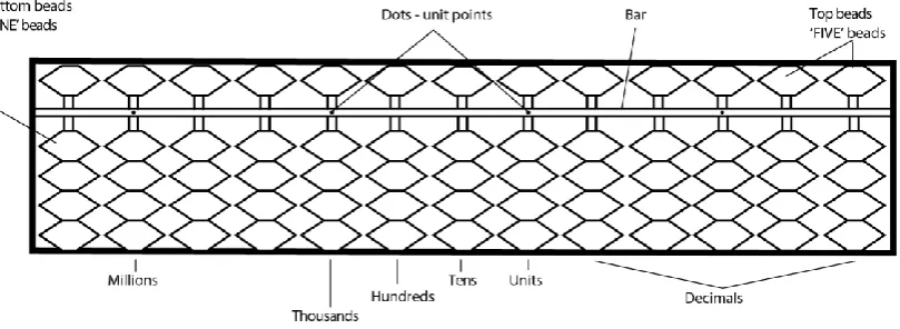
[image:23.595.121.526.258.406.2]Each columns configuration represents decimal numeral value, ranges from 0 to 9 according to its decimal position. Figure 2.7 shows the beads configuration with respect to equivalent decimal numbers. Calculations of round number shall begin at the second dot from the right. The initial value of 0 is achieved when no beads is touching the bar and value of beads are counted otherwise. The addition of value 5 and 1‟s concludes the possibilities of achieving numeral representation of 0 to 9.These principles are applied for all the columns, providing various possibilities of numeral representation.
Figure 2.6: Japanese abacus construction and notations
Figure 2.7: Japanese abacus beads position and numerical value
2.4 Abacus Arithmetic Operation
[image:23.595.118.522.477.613.2]like calculator, but providing the process of achieving the same goal as a counting machine. Each arithmetic operation requires different technique and will be discussed further.
The important rules of arithmetic operation using abacus is, to begin the process from left bead rods to the right and the use of complementary numbers of 5‟s or 10‟s. Each technique of complementary numbers is grouped into itstotal sum such as combination of 4 and 1 or 3 and 2 for complementary number of 5‟s. The rules is also applied for complementary of 10‟s which group into five possible combinations.
2.4.1 Addition
The following procedure perform an addition operation of 45.7 + 4.5. The method of complementary numbers is demonstrated.
4 5 . 7 Step 1
4 5 . 7 4
4 9 . 7
Step 2
4 5 . 7 -5 4 9 . 2
-9
4 0 . 2 +1
5 0 . 2
Step 3
Step 4
11
Figure 2.8 illustrate the complete additional operation which is summarized into the following step. First step is to set the initial value of the arithmetic operation. 45.7 is set according to its decimal places. Second step is by adding value of 4 to unit rod without its decimal values. Followed by adding 0.5 to the rod of tenth, this achieved by subtracting the value of complement 10‟s (5). Then, value of 1 is carried into the unit rod. Adding the value of carry is by subtracting it with the complementing value of carry (complement of 1 is 9). The carry value on unit rod is bring forward to the tens rod. Addition of the last carry value to the tens rod resulting the final value at 50.2.
2.4.2 Subtraction
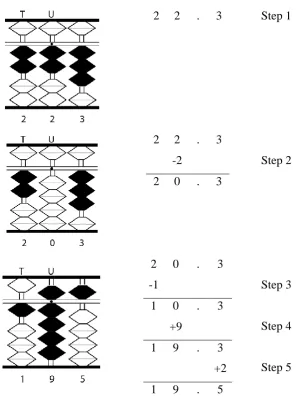
An arithmetic operation of 22.3-2.8 require different procedure compared to addition operation. Illustration in Figure 2.9 shows detail steps of conducting subtraction using abacus.
First step is to set the initial value of 22.3. Next, is to subtract the second value without its fractional value, giving the subtraction of initial value with 2. This result in a new value of 20.3. Subtract its factional value according to its decimal places, hence subtracting 8 from the tenth rod. The subtraction of 3 to 8 on the tenth rod is not possible, as the minuend is larger than subtrahend. This require borrowing from the unit rod but no value in the unit column. The unit column is borrowing form the tens column, thus subtracting 1 from the tens column, hence adding 9 to unit column. The borrowing from unit column resulting the complement of value 8 to +2. This event produces an addition of 3 on tenth column, resulting the final value of 19.5.
2.4.3 Multiplication
13
2 2 . 3 Step 1
2 2 . 3 -2
2 0 . 3
Step 2
2 0 . 3 -1
1 0 . 3 +9
1 9 . 3 +2 1 9 . 5
Step 3
Step 4
[image:27.595.125.428.83.488.2]Step 5
Figure 2.9: Subtraction Operation
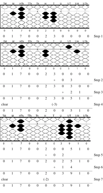
An arithmetic operation of 2.3×17 on abacus will be explained by the following procedures. In this operation, it processes the total of three whole numbers which contributed by two whole number on the multiplier and a single unit on the multiplicand. The position of multiplier or multiplicand is set by the user, but must be separated by at least two empty columns.
Set multiplier 17 at the far most left hand side with an empty column at the beginning. Set the multiplicand of 23, at two columns spacingafter the last multiplier value. This step is as illustrated in Figure 2.10,Step 1. Further to the right, leave an empty column after the multiplier and set the next column (1/T) as the unit rod.
added to reference unit tenth (column 1/H). Clear the value of 3 in multiplicand column,indicating that this process section is completed. The current value of this operation is as illustrated in Figure 2.10, Step 4.
The similar operation is applied to the balance multiplicand. The product of 2×1 (actual multiplication of 2×10) is added to reference tens column (column U) and the product of 2×7 (actual multiplication of 2×7) is added to the reference unit tens (column U). Clearing the multiplicand value (2) at its respective column is necessary to acquire the final value. The final product of the multiplication is 391. As the reference unit is at column 1/T, the actual value become 39.1. This multiplication process detailsis as illustrated in Figure 2.10.
2.4.4 Division
The application of division operation took different approach. The abacus committee agreed to separate dividend and divisor by four empty rods, but the consideration must be given for a smaller sized abacus[5].
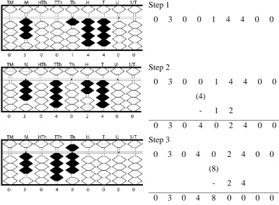
A division operation of 144 ÷ 3 on the abacus is as illustrated in Figure 2.11. The dividend (144) has three whole numbers, whereas the divisor has only a single whole number but additional a single spacing givenresulting two columns for the divisor. Set the divisor at far most left column, leaving two empty consecutive columns,giving the divisor at rod position thousands to tens. This configuration is depicted on Figure 2.11, Step 1.
15
0 1 7 0 0 2 3 0 0 0 0 Step 1
0 1 7 0 0 2 3 0 0 0 0
+ 0 3 Step 2
0 1 7 0 0 2 3 0 3 0 0
+ 2 1 Step 3
0 1 7 0 0 2 3 0 5 1 0
clear (-3) Step 4
0 1 7 0 0 2 0 0 5 1 0
0 1 7 0 0 2 0 0 5 1 0
+ 0 2 Step 5
0 1 7 0 0 2 0 2 5 1 0
+ 1 4 Step 6
0 1 7 0 0 2 0 3 9 1 0
clear (-2) Step 7
[image:29.595.127.483.63.728.2]0 1 7 0 0 0 0 3 9 1 0
The partial quotient value of 4 and the remainder dividend of 4 is added (4+4=8), and positionedat the lower column compared to the previous quotient. The current quotient value of 8 is multiplied by 3 (8×3=24), and the multiplication product is subtracted from the current value at the lower reference points from the previous step. Illustrated as Step 3 in Figure 2.11, the final value is 48. The last quotient column indicates the decimal point notation.
Step 1
0 3 0 0 1 4 4 0 0
Step 2
0 3 0 0 1 4 4 0 0 (4)
- 1 2
0 3 0 4 0 2 4 0 0 Step 3
0 3 0 4 0 2 4 0 0 (8)
- 2 4
[image:30.595.112.513.216.510.2]0 3 0 4 8 0 0 0 0
Figure 2.11: Division Operation
2.5 Previous Related Works
17
teaching by using his invention. These mechanical inventions however require different arithmetic solving technique compared to the well-established Chinese or Japanese abacus.
Electronic abacus develop by KLN KLEIN Production Development Inc.[12], features five columns of optical switches that resemble the abacus bead. This device however, does not have the display feature included. An invention by Junji Hiromori[13]combined both electronic calculator and abacus thus provide simultaneous function of traditional counting machine and modern computation. The utilization of numerical keypad as dual function of abacus beads and keypad is an advancement to traditional abacus,however the movement of abacus bead must be done independently to avoid operational errors. The invention of Indian Abacus[14]by Naina Mohamed and Basheer Ahamed is a hardware based electronic abacus. The function of abacus is emulated by a 13×5 grid of sliding switches.The operational result is later displayed on LCD screen or sent via USB,in order for the result to be posted through the internet. This capability enables the Indian Abacus to be used in primaryand secondary abacus competition, thus emphasised as educational tools. The Digicus[15] is a combination of traditional Japanese abacus with a calculator. Developed by Sharp Inc., this invention operates independently. The calculator is attached as a component of the whole system and does not integrated with each other, hence not categorised as electronic abacus. Even though most of these design features enhance the function of the abacus which enables better understanding of mathematical operations, the authenticity is not well preserved.
Electronic abacus proposed by Alison Barker[18] is equipped with electronic sensors which detect the abacus bead position.The data is transmitted through USB and displayed on the computer screen. The additional features of audible capabilities and magnified text enable this prototype to be used by visually impaired personnel and normal person as well. The development of E-Abacus by Mohamad Solehin Robian [19] and Abd Kadir Mahamad et al.[20], demonstrate the integration of traditional abacus with the use of sensors and microcontroller. This integration produces flexible application, and enabling the abacus to be operated individually or with the aid of microcontroller computation.The ability of displaying the arithmetic representation according to abacus bead positions and result from arithmetic operation on LCD screen is the distinctive features of this invention. Complex circuitry and bulky size are the major drawback for this design due to the use of two separate processors, each for bead sensor circuitry and LCD display.
2.6 Summary of Previous Related Works
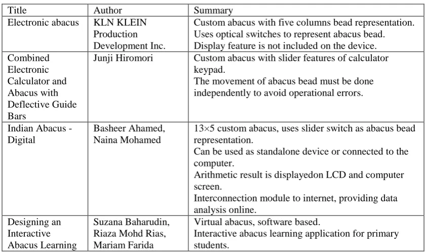
[image:32.595.106.526.516.765.2]The listed previous related works in Table 2.1 is summarized based on the configuration that features electronic element thus excluding the inventions that uses only mechanical features.
Table 2.1: Summary of previous related works
Title Author Summary
Electronic abacus KLN KLEIN
Production Development Inc.
Custom abacus with five columns bead representation. Uses optical switches to represent abacus bead. Display feature is not included on the device. Combined Electronic Calculator and Abacus with Deflective Guide Bars
Junji Hiromori Custom abacus with slider features of calculator
keypad.
The movement of abacus bead must be done independently to avoid operational errors.
Indian Abacus - Digital
Basheer Ahamed, Naina Mohamed
13×5 custom abacus, uses slider switch as abacus bead representation.
Can be used as standalone device or connected to the computer.
Arithmetic result is displayedon LCD and computer screen.
Interconnection module to internet, providing data analysis online.
Designing an Interactive Abacus Learning
Suzana Baharudin, Riaza Mohd Rias, Mariam Farida
Virtual abacus, software based.
19
Application for Beginners: A Prototype
Ahmad Limited arithmetic operation until numeral of 20.
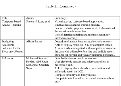
Table 2.1 (continued)
Title Author Summary
Computer-based Abacus Training
Steven N. Long et al. Virtual abacus, software based application.
Emphasized as abacus training module.
Feature realistic graphical movement of abacus bead during arithmetic operation.
Lots of detailed notation and menu selection for interactive learning.
Designing Accessible Software for the Electronic Abacus
Alison Barker Detection of abacus bead using electronic sensors.
Able to display result on LCD or computer screen. Abacus module integrated with computer to visualise the data with adjustable font size and audible result. Suitable for normal and visually impaired personnel.
E-Abacus Mohamad Solehin
Robian, Abd Kadir Mahamad, Sharifah Saon
Detachable abacus unit from module.
Uses electronic sensors and microcontrollers as processing unit.
Able to display abacus beads representation and arithmetic result on LCD.
Complex circuitry and bulky in size.
[image:33.595.107.529.116.414.2]CHAPTER 3
METHODOLOGY
3.1 Introduction
A procedure of outlining the research methodology is crucial in achieving the research objectives. A well-planned methodology could be used as a documented guideline prior to conducting of any experiment which leads to the reduction of complications. The following project methodology is focused on the abacus sensor circuitry design, hardware interface to DE2 board, source code flow chart, simulation method and operational procedures. The synchronism of hardware setup and VHDL programming is essential for an orderly operated Electronic Abacus.
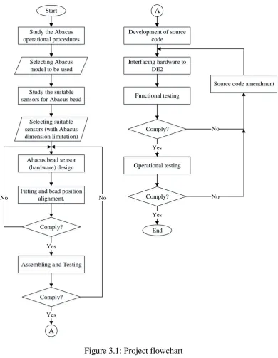
3.2 Project Activities
21
Start
Study the Abacus operational procedures
Selecting Abacus model to be used
End Study the suitable
sensors for Abacus bead
Selecting suitable sensors (with Abacus dimension limitation)
Abacus bead sensor (hardware) design
Comply? No
Fitting and bead position alignment.
Assembling and Testing
Comply? Yes
No
A Yes
Development of source code
A
Interfacing hardware to DE2 Functional testing Comply? Operational testing Comply? Yes Yes
Source code amendment
No
[image:35.595.131.522.66.570.2]No
Figure 3.1: Project flowchart
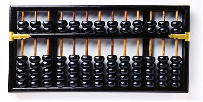
3.3 Hardware Design
abacus with the dimensions as illustrated in Figure 3.2 is chosen due to its medium size that offers flexibility of sensors used.
Figure 3.2: Abacus model used in hardware design
This model consists of thirteen columns with a single bead on the top and four beads at the bottomof the abacus separator. As sensor board will be placed inside the abacus inner dimension, thus minor modification is required. Figure 3.3 illustrate the comparison between the original states of abacus with the modified version.
Original condition of abacus
23
Figure 3.3: Abacus modification
Two parts of boardare required to position the sensor as close as possibleto the respective beadensuring proper sensor triggering. The first board(bead sensor) is dimensioned respective to the abacus hollow inner dimension, served as the locking mechanism to ensure the abacus is stationary during operation. The second board (DE2 interface) serves as an interface to DE2 board thus providing an elevation in order to position the sensor beads with minimal distance to it respective abacus beads. Figure 3.4 shows the DE2 interface board design, whereas Figure 3.5 illustrate the elevation provided by DE2 interface board. Figure 3.6 shows the positioning of bead sensor and interfaceboard respective to abacus bead.The average spacing from abacus base to the abacus beads is approximately at 7.45mm. Total elevation given by the abacus sensor board is 4.6mm, and with an additional height of abacus sensor of 1.5mm, giving the total distance from PCB base to the sensor at 6.1mm. So, the distance between abacus beads and its respective sensor is approximately at 1.35mm.
Figure 3.4: DE2Interface board
[image:37.595.117.525.604.769.2]Figure 3.5: Bead sensor board elevation
The main function of using proximity sensor in this design is to detect the presence of abacus bead without any physical contact, while keeping distance between the sensors with abacus bead to minimal. Reflective interrupter SH9206 is used as the abacus proximity bead sensor. The packaging of this device allows a precision fitting in a concise space and due to the use of surface mount component, the position of the sensors will be uniform. The sensors are aligned into 13×5 matrix grid, and positioned precisely according to the centre of bead position in each rows and columns. Figure 3.7 depicted the positioning of each sensoron the bead sensor board. The abacus reset mechanism is removed as the reset bar is located at the same height of the abacus bead, assuring accuracy of bead position detection.
Figure 3.6: Multistage boardconfiguration with respect to abacus bead Abacus beads
Proximity Sensor Bead sensor board
DE2 Interface board
[image:38.595.115.524.600.749.2]72
REFERENCES
1. Mahpop, H. and Sivasubramaniam, P. Addition of Whole Numbers with Regrouping using the “Soroban”. Procedia Social and Behavioral Sciences.
2010. 8: 50–56.
2. Berg, T. (2016). Typoscriptics. Retrieved on November 1, 2016, from http://www.typoscriptics.de/old/soroban/resources/league-manual.pdf
3. Frieman, S. R. Abacus. USA Patent US 2007/0166673 A1. 2007.
4. Cusick, J. (2015). The Japanese Soroban: A Brief History and Comments on its Educational Role. Retrieved on November 1, 2016, from https://www.researchgate.net
5. Heffelfinger, T. and Flom, G. (2004). Abacus: Mystery of the Bead. Retrieved on November 11, 2016, from http://webhome.idirect.com/~totton/abacus/ 6. Dobryshina, E. V., Drogin, A. V., Rimsky, D. S. and Sheypak, S. A. (2006).
Russian Stchoty in Historical Sources. Retrieved on December 4, 2016, from http://schoty.3neko.ru/main.html
7. Fernandes, L. (2015). The Abacus: A Brief History. Retrieved on December 4, 2016, from http://www.ee.ryerson.ca:8080/~elf/abacus/history.html
8. Collazo, F. J. (2005). A Brief History of the Abacus. Retrieved on December 4, 2016, from http://www.fjcollazo.com/documents/AbacusHist.htm
9. Eastaugh, B. and Sternal-Johnson, C. (2016). Education in Japan Community
Blog. Retrieved on December 1, 2016, from
https://educationinjapan.wordpress.com/of-methods-philosophies/saluting-the-soroban-j-abacus/the-invention-of-the-abacus-or-soroban/
10. Markarian, K. (2016). Japan Society of the UK. Retrieved on November 1,
2016, from
http://www.japansociety.org.uk/wp-content/uploads/2015/01/soroban_1.pdf
12. KLN KLEIN Product Development Inc. KLN KLEIN Product Development Inc. - Electronic Abacus. Retrieved on December 7, 2016, from http://www.klnklein.com/proj71.html
13. Hiromori, J. Combined Electronic Calculator and Abacus with Deflective Guide Bars. Japan Patent 5,134,692. 1989.
14. Basheer,A.and Mohamed,N.Indian abacus - digital. India Patent WO2013121432 A1. 2012.
15. RetroCalculators. Hybrid-Sorokaru, Digicus-Sorocal Soroban Abacus and Digital Calculator.Retrieved on November 15, 2016 from http://retrocalculators.com/digicus.htm
16. Baharudin, S., Rias, R. M. and Ahmad,M. F. Designing an Interactive Abacus Learning Application for Beginners: A Prototype.International Conference on User Science Engineering (i-USEr). 2010.
17. Long, S. N., Belt, C. D., Golightly, C., Lisonbee, J., Oaks, G.and Nelson, M. H. Computer-based Abacus Training. USA Patent 8,672,683 B2. 2014.
18. Barker, A. Designing Accessible Software for the Electronic Abacus.16th International Workshop on Database and Expert Systems Applications. 2005. 19. Robian, M. S. Development of Electronic Abacus.Degree Thesis. Universiti
Tun Hussein Onn Malaysia; 2015.
20. Mahamad, A. K., Robian, M. S. and Saon, S. Development of E-Abacus.ARPN Journal of Engineering and Applied Sciences. 2015. 10(19): 8516 - 8519.
21. OSRAM Opto Semiconductor.Reflective Interrupter SFH 9206. OSRAM Opto Semiconductors GmbH. 2012.
22. Larson, S. (2013).Character LCD Module Controller (VHDL). Retrieved on
March 26, 2017, from
https://eewiki.net/pages/viewpage.action?pageId=4096079#CharacterLCDM oduleController(VHDL)
23. Bernazzani, D. (2005). The Soroban / Abacus Handbook. Retrieved onMarch
26, 2017, from
http://sliderulemuseum.com/Abaci/THE_ABACUS_HANDBOOK.pdf. 24. Kementerian Pelajaran Malaysia. Modul Abakus dan Aritmetik Mental, Edisi
74
25. Kuang, W. (2016). A Case Study: using LCD Module on DE2 Board.
Retrieved onNovember 1, 2016, from
http://faculty.utpa.edu/kuangw/courses/ELEE4303/ch8_part3.pdf
26. Kojima, T. Advanced Abacus Japanese Theory and Practice.Tuttle Publishing.2012.
27. Daware, M. H. and Patil, A. S. Implementation of I2C Bus Protocol on FPGA.International Journal of Current Engineering and Scientific Research (IJCESR).20152(8).
28. Sunku,S. and Mutyala, L. L. Design of I2C BUS Controller using VHDL.International Journal of Emerging Engineering Research and Technology. 20153(8):125-129.
29. Tanjila, S., Swapnil,K. and Sarla, P. Implementing an I2C Bus on FPGA.International Journal of Multidisciplinary Research and Development. 20152(4): 283-285.
30. Hwang, E. (2008). Implementing an I2C Master Bus Controller in a
FPGA.Retrieved onMarch 11, 2017, from
http://faculty.lasierra.edu/~ehwang/digitaldesign/public/projects/DE2/I2C/I2 C.pdf.
31. Venkatesh, V.,Dayanand D. and Padhy, S. K. C. VHDL implementation for design of an I2C Interface for Temperature Sensor and an EEPROM Memory.International Journal of Advanced Research in Computer Engineering & Technology (IJARCET). 20154(4): 1571-1575.
32. Sahu, A., Mishra,R. S.and Gour, P. An Implementation of I2C using VHDL for DATA surveillance.International Journal on Computer Science and Engineering (IJCSE). 20113(5): 1857-1865.
33. Hathwalia,S.and Sankhyan, S. C. A Novel Approach for Displaying Data on LCD Using FPGA.International Journal of Technical Research and Applications. 20131(4): 48-51.
34. Brown, S. and Rose, J. (2002). Architecture of FPGAs and CPLDs: A Tutorial. Retrieved onMarch 11, 2017, from https://www.researchgate.net 35. Mui, E. N.FPGA Interfacing of HD44780 Based LCD Using Delayed Finite
36. Ashenden, P.J. and Lewis, J. The Designer’s Guide to VHDL. Third
Edition.Morgan Kaufmann. 2008.
37. Short, K. L. VHDL for Engineers. Pearson Education. 2009.
![Figure 2.2: Replica of Roman Abacus[6]](https://thumb-us.123doks.com/thumbv2/123dok_us/8757836.893293/20.595.158.482.196.376/figure-replica-of-roman-abacus.webp)
![Figure 2.5: The evolution of counting devices[7]](https://thumb-us.123doks.com/thumbv2/123dok_us/8757836.893293/22.595.113.526.391.490/figure-the-evolution-of-counting-devices.webp)