Journal of Chemical and Pharmaceutical Research, 2015, 7(6):347-360
Research Article
CODEN(USA) : JCPRC5
ISSN : 0975-7384
Development of correlations for thermal effectiveness of two-phase liquid –
liquid systems in a tube side – shell and tube heat exchanger
V. Alagesan
Department of Chemical Engineering, School of Chemical and Biotechnology, SASTRA University, Thanjavur, Tamilnadu, India
_____________________________________________________________________________________________
ABSTRACT
Experiments were carried out on heat transfer between hot water and various two-phase liquid mixtures in a custom-built 1-2 shell and tube heat exchanger. The two-phase liquid systems were chosen to represent wide range of thermo-physical and transport properties. The influence of mass flow rate of hot fluid & two-phase liquid mixture, composition of phase liquid mixture, flow geometry (tube/shell side) on thermal effectiveness of two-phase liquid mixture were comprehensively studied in laminar flow regime. The experimental data was statistically analyzed to develop a correlation for thermal effectiveness of two-phase liquid mixture on tube side. The developed correlation predicts thermal effectiveness of two-phase liquid mixture with a maximum error of ±15 % for 240 data points covering 7 different two-phase liquid systems.
Keywords: Two-phase liquid mixture, heat transfer, thermal effectiveness, correlation, Reynolds number, heat capacity ratio
_____________________________________________________________________________________________
INTRODUCTION
Many industrial applications involve heat transfer in various multiphase systems viz., gas-liquid, liquid-liquid, liquid-solid and gas-solid. Heat transfer in flow boiling[1], pneumatic conveying and preheating in drying systems [2] – [7], cyclone heat exchanger [8], fluidized beds [9], etc. are some of the examples. Heat transfer in liquid-liquid two-phase systems is widely prevalent in petrochemical industries [10]. The presence of one liquid along with other liquid forming two-immiscible phases with different thermo-physical properties changes momentum and heat transfer characteristics. Hence the understanding of heat transfer in such two-phase systems is essential, which can be utilized for design and analysis of heat transfer equipment.
V. Alagesan
J. Chem. Pharm. Res., 2015, 7(6):347-360
______________________________________________________________________________
heat transfer between a single phase stream and a two-phase stream for a reasonably wide variety of liquids constituting two phases.
EXPERIMENTAL SECTION
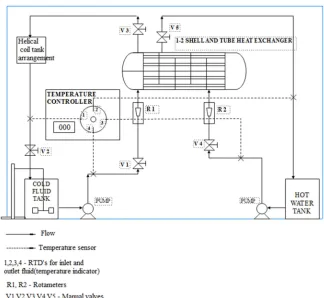
[image:2.595.143.467.277.575.2]The 1-2 pass shell and tube heat exchanger used for heat transfer experiments is described in our earlier work [42]-[46] and a schematic diagram is shown in Figure 1. Heat transfer area of 0.2269 m2 was obtained by arranging 14 tubes (0.01 m ID and 0.012 m OD) in triangular pitch pattern. Each tube is 0.43 m long. The hot and cold fluids (hot water and two-phase liquid mixtures respectively) were pumped to the heat exchanger using 1/4 HP pumps and the flow rates were measured using calibrated rotameters with an accuracy of ±0.1 LPM. Flow rates of hot and cold streams were adjusted using hand operated valves. A thermostat (accuracy ~±0.5oC) was used to maintain the temperature of hot fluid (hot water). An agitator was used to ensure constant mixing of two fluids (in two-phase stream) in the reservoir. Seven liquid-water systems viz. Kerosene-water, Diesel-water, Nitro benzene-water, Oleic acid-water, Palm oil-water, Octane-water and Dodecane-water in varying proportions were used for experiments. This experimental design yielded 7 two-phase systems with 4 compositions each leading to 28 different two-phase mixtures. The range of variables investigated are given in Table 1. The range of thermo-physical & transport properties of various pure liquids used for formulation of two-phase, liquid-liquid systems are given in Table 2.
Figure 1: A schematic view of the experimental set-up
Table 1: Range of variables investigated
S.no Variables Values
1 Composition of two-phase systems (as volume percentage of organic phase) 20%, 40%, 60%, 80% and 100%
2 Mass flow rate of cold fluid 0.0088 kg/s to 0.2412 kg/s (shell side) 0.0043 kg/s to 0.1062 kg/s (tube side) Table 2: Range of properties of two-phase systems investigated
S.No Properties Notation Range Unit 1 Dynamic viscosity µ 0.001 to 0.05 kg/ms 2 Density ρ 678 to 1199 kg/m3 3 Thermal conductivity k 0.129 to 0.624 W/mK
RESULTS AND DISCUSSION
1.1. Effect of Reynolds number on thermal effectiveness of process fluid:
Figure 2 shows the effect of Reynolds number on thermal effectiveness of process stream, when it was supplied through the shell-side. Figure 2 has been drawn for different compositions of kerosene-water system as the process stream. It is observed from Figure 2 that the thermal effectiveness of process stream decreases with increase in its Reynolds number. For a process stream of fixed composition, higher Reynolds number indicates higher velocity and hence higher mass flow rate of process stream. Though heat transfer coefficient is expected to increase with velocity of process stream, the higher heat capacity (product of mass flow rate and specific heat) of process stream leads to reduction in its temperature rise. Hence thermal effectiveness of process fluid decreases with increase in Reynolds number.
The thermal effectiveness of 100% water as process stream is higher than that of 100 % kerosene as process stream for the same Reynolds number. The thermal effectiveness for two-phase process streams lies between the thermal effectiveness of 100 % water and 100 % kerosene as process stream. The viscosities of kerosene-water mixtures are higher than the viscosity of water. Hence to maintain the same Reynolds number, higher velocity and hence higher mass flow rate must be used for kerosene-water mixture. This leads to increase in heat capacity, which in turn reduces the temperature rise. Pure kerosene has the highest viscosity among kerosene-water systems and has the lowest thermal effectiveness due to increase heat capacity required to maintain the desired Reynolds number. Similar behavior has been observed for other two-phase process streams also as shown in Figures 3 to 8.
V. Alagesan
J. Chem. Pharm. Res., 2015, 7(6):347-360
______________________________________________________________________________
Figure 3: Influence of Reynolds number on Thermal effectiveness of diesel-water system
Figure 5: Influence of Reynolds number on Thermal effectiveness of oleic acid-water system
V. Alagesan
J. Chem. Pharm. Res., 2015, 7(6):347-360
______________________________________________________________________________
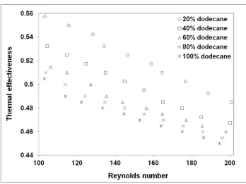
[image:6.595.132.480.66.327.2]Figure 7: Influence of Reynolds number on Thermal effectiveness of dodecane-water system
Figure 8: Influence of Reynolds number on Thermal effectiveness of octane-water system
1.2. Effect of velocity ratio on thermal effectiveness of process fluid in tube side:
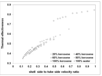
Figure 9: Influence of Shell side to tube side velocity ratio on thermal effectiveness of kerosene-water system
V. Alagesan
J. Chem. Pharm. Res., 2015, 7(6):347-360
______________________________________________________________________________
Figure 11: Influence of Shell side to tube side velocity ratio on thermal effectiveness of palm oil-water system
Figure 13: Influence of Shell side to tube side velocity ratio on thermal effectiveness of NB-water system
V. Alagesan
J. Chem. Pharm. Res., 2015, 7(6):347-360
[image:10.595.132.488.66.328.2]______________________________________________________________________________
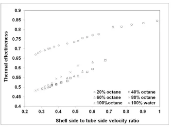
Figure 15: Influence of Shell side to tube side velocity ratio on thermal effectiveness of octane-water system
To understand this observation, one may derive an expression relating thermal effectiveness and velocity ratio as follows:
Thermal effectiveness of process stream is
(
)
(
hi ci)
ci co
T
T
T
T
S
−
−
=
(1)Rewriting Eq. (1) in terms of heat transfer rate and heat capacity,
S
=
Q
mCp
(
)
cold(
T
hi−
T
ci)
(2)
For fixed heat exchanger geometry, heat transfer rate may be expressed as the product of overall heat transfer coefficient, heat transfer area and driving force. Accordingly Eq. (2) becomes,
(3)
Neglecting the heat transfer resistance in the tube wall, overall heat transfer coefficient may be related to shell side
and tube side heat transfer coefficients, ho and hi respectively.
Therefore, Eq. (3) becomes
i o
h
h
U
1
1
1
+
=
(4)i o i o
h
h
h
h
U
+
=
(5)Substituting Eq. (5) in Eq. (3)
(
mCp
) (
coldT
hiT
ci)
(
o i)(
) (
cold hi ci)
i oT
T
mCp
h
h
T
h
h
S
−
+
∆
=
(6)If shell side and tube side velocities are ‘v’ and ‘u’ respectively, Eq. (6) may be written for the two-phase on the shell-side as follows, accounting heat transfer coefficient-velocity relationship in the power law form,
(
n m)
(
hi ci)(
)
coldm n
ACp
v
T
T
u
v
T
A
u
v
S
ρ
−
+
∆
=
(7)In Eq. (7), m & n are exponents in
h
i=
m
1u
mand
h
o=
n
1v
nEq. (7) becomes
(
)
(
hi ci)
(
p)
cold m n m nAC
T
T
u
v
T
A
u
v
S
ρ
−
+
∆
=
−1 (8)For a constant tube side fluid velocity (u), Eq. (8) may be simplified as follows:
+
− nu
v
k
v
S
1
1
α
(9)where k is um-n, constant at constant tube velocity
From Eq. (9), it is evident that the thermal effectiveness decreases with ‘v’ or (v/u) ratio. The rate of decrease depends on ‘n’ in heat transfer coefficient-shell side velocity relationship.
Figures 9 to 15 show the influence of shell-side to tube-side velocity ratio on thermal effectiveness of process fluid when supplied in the tube side. It may be observed from Figure 9 to 15 that the thermal effectiveness of two-phase liquid mixture increases with increase in shell-side to tube-side velocity ratio, for all the two-phase systems when they are supplied inside the tubes. This observation may be explained as follows:
For constant shell side velocity, but varying tube-side velocities for two-phase mixture flowing inside the tubes, Eq. (6) may be modified as follows:
(
)
(
hi ci)(
)
coldm n m n
ACp
u
T
T
u
v
T
A
u
v
S
ρ
−
+
∆
=
(10)u
v
u
u
S
n m m
+
1
α
(11)V. Alagesan
J. Chem. Pharm. Res., 2015, 7(6):347-360
______________________________________________________________________________
Power law type function was assumed, following the conventional correlations for heat transfer coefficient and Nusselt number. Tube diameter and two-phase velocity were taken as characteristic dimension and characteristic velocity in Reynolds number. Heat capacity ratio is the ratio of heat capacity of the two-phase fluid to the heat capacity of single-phase fluid (hot fluid in this case).
The regression equation for thermal effectiveness (S) for the two-phase liquid mixture was obtained using Minitab-14 as follows:
163 . 0 226 . 0 257 . 0
Pr
Re
156
.
0
− −=
F
S
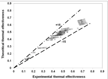
for two-phase systems in tube side (13) [image:12.595.135.482.235.488.2]Figure 4 shows the comparison between the experimental values of thermal effectiveness and those calculated using Eqn. (13). It is evident from Figure 4 that the Eqn. (13) predicts the thermal effectiveness for the two-phase within ± 15% error for seven liquid-liquid systems for about 240 data points.
Figure 4: Variation between experimental and predicted values of thermal effectiveness for different compositions of liquid-liquid systems in tube side
CONCLUSION
Thermal effectiveness of two-phase liquid mixture decreases with velocity in a 1-2 shell and tube heat exchanger. However, the thermal effectiveness increases with Reynolds number in the laminar flow regime. The dependence of thermal effectiveness on Reynolds number follows power-law relationship, with higher exponent when the two-phase mixture is supplied on the tube-side. Similarly, the thermal effectiveness of two-two-phase mixture is more sensitive to heat capacity ratio while being supplied on the shell-side, compared to that supplied on the tube-side. The developed correlation predicts thermal effectiveness of two-phase liquid system with a maximum error of ± 15 % for wide range of data points covering 7 different two-phase liquid systems.
Nomenclature
A Heat transfer area, m²
p
c
Specific heat of process stream, J/kg K Di Inner diameter of the tube, mDo Outer diameter of the tube, m
Ds Inner diameter of shell, m
k Thermal conductivity of cold fluid, W/mK m Mass flow rate of process stream, kg/s NNu Nusselt number
NPr Prandtl number
NRe Reynolds number
S Thermal effectiveness of process stream Thi Inlet temperature of hot water, K
Tho Outlet temperature of hot water, K
Tci Inlet temperature of cold fluid, K
Tco Outlet temperature of cold fluid, K
Q Volumetric flow rate of process stream, m³/s U Overall heat transfer coefficient, W/m2K Greek letters
∆T Temperature difference in process side, K µ Viscosity of cold fluid, kg/ms
ρ Density of cold fluid, kg/m³
REFERENCES
[1]Z Zhou; X Fang; D Li, Sci. World J., 2013, 4(4), 458-797.
[2]KS Rajan; SN Srivastava; B Pitchumani; V Surendiran, Int. J. Therm. Sci., 2010, 49(1), 182-186. [3]KS Rajan; SN Srivastava; B Pitchumani; K Dhasandhan, Appl. Therm. Eng., 2008, 28(14), 1932-1941.
[4] KS Rajan; K Dhasandhan; SN Srivastava; B Pitchumani, Int. J. Heat Mass Tran., 2008, 51(11-12), 2801-2813. [5]KS Rajan; SN Srivastava; B Pitchumani; B Mohanty, Appl. Therm. Eng., 2007, 27(8), 1345-1351.
[6]KS Rajan; B Pitchumani; SN Srivastava; B Mohanty, Int. J. Heat Mass Tran., 2007, 50, 967-976.
[7]KS Rajan; SN Srivastava; B Pitchumani; B Mohanty, Int. Commun. Heat Mass Tran., 2006, 33, 1234-1242. [8]A Jain; B Mohanty; B Pitchumani; KS Rajan, J. Heat Tran., 2006, 128(8), 761-768.
[9]R Sundaresan; AK Kolar, Appl. Therm. Eng., 2013, 50, 985-996.
[10]AM Saravanan; M Jeykumar; S Sundaram, Int. J. Design Manuf. Technol., 2009, 3(6), 73-76. [11]T Johannessen, Int. J. Heat Mass Tran., 1972, 15, 1443-1449.
[12]RW Lockhart; RC Martinelli, Chem. Eng. Prog., 1949, 43(1), 39-48. [13]D Chisholm, Int. J. Heat Mass Tran., 1967, 10(12), 1767-1778.
[14]S Badie; CP Hale; CJ Lawrence; GF Hewitt, Int. Journal of multiphase flow, 2000, 26, 1525-1543.
[15]HR Rani; P Partheeban; S Sundaram, ISA TECH/EXPO Technology Update Conference Proceedings, 2002, 424-425, 1102-1116.
[16]S Partheban; H Rani; S Sundaram; P Saratchandrabyabu, Int. J. Heat Mass Tran., 2005, 48, 2911-2921. [17]SM Ghiaasiaan; X Wu; DL Sadowski; SI Abdel-Khalik, Int. J. Multiphase Flow, 1997, 23, 1063-1083. [18]GP Xu; CP Tso; KW Tou, Int. J. Multiphase Flow, 1998, 24(8), 1317-1342.
[19]R Dowlati; AMC Chan; M Kawaji, J. Fluid Eng., 1992, 114(3), 450-456.
[20]AC Awwad; ZF Xim; M Dong; A Ebadiam; HM Soliman, J. Fluid Eng., 1995, 117, 720-726.
[21]A Awwad; ZF Dong; MA Ebadiam; HM Soliman; RC Xin, Int. J. Multiphase Flow, 2000, 21, 607-619. [22]ZY Bao; DF Fletcher; BS Haynes, Int. J. Heat Mass Tran., 2000, 43, 2313-2324.
[23]CJ Downess; GR Hedwig; M Fourar; S Bories, Int. J. Multiphase Flow, 1995, 21(4), 621-637. [24]TS Zhao; QC Bi, Int. J. Heat Mass Tran., 2001, 44, 2523-2534.
[25]JL Alcock; DR Webb, Int. J. Heat Mass Tran., 1997, 40, 4129-4135.
[26]P Argyropoulos; P Bontozoglou; G Karagiannis; V Vlasogiannis, Int. J. Multiphase Flow, 2002, 28(5), 757-772.
V. Alagesan
J. Chem. Pharm. Res., 2015, 7(6):347-360
______________________________________________________________________________
[40]JYL Lum; J Lovick; P Angeli, Can. J. Chem. Eng., 2004, 82(2), 303-315.
[41]S Sathiyan; M Rangarajan; S Ramachandran, Brazilian Journal of Chemical Eng., 2013, 30(2), 311-321. [42]V Alagesan; S Sundaram, Journal of Theoretical and Applied Information Technology, 2011, 32(2), 107-117. [43]V Alagesan; S Sundaram, Brazilian J. Chem. Eng., 2012, 29(2), 275-283.