Speed Control of DC Motor Using Artificial Bee Colony
Optimization Technique
Akhilesh Kumar Mishra
1,*Anukaran Khanna
1,
Navin Kumar Singh
2,Vivek K. Mishra
21M.Tech. Scholar, Department of Electrical Engineering,Motilal Nehru National Institute of Technology, Allahabad, India 2M.Tech. Scholar, Department of Electrical Engineering, SHIATS (Earlier known as Agriculture Institute), Naini, Allahabad, India
*Corresponding Author: [email protected]
Copyright © 2013 Horizon Research Publishing All rights reserved.
Abstract
The aim of this work is to design a speed controller of a DC motor by selection of PID parameters using bio-inspired optimization technique of Artificial Bee Colony Optimization (ABC). Here, model of a DC motor is considered as a second order system for speed control. In this work bio-inspired optimization technique in controllers and their advantages over conventional methods is discussed using MATLAB/Simulink. This proposed optimization methods could be applied for higher order system also to provide better system performance with minimum errors. The main aim is to apply ABC technique to design and tune parameters of PID controller to get an output with better dynamic and static performance. The application of ABC to the PID controller imparts it the ability of tuning itself automatically in an on-line process while the application of optimization algorithm to the PID controller makes it to give an optimum output by searching for the best set of solutions for the PID parameters.Keywords
Artificial Bee Colony Optimization; PID Controller; Parameter Tuning1. Introduction
DC motor drives are widely used in applications requiring adjustable speed, good speed regulations and frequent starting, braking and reversing. Some important applications are rolling mills, paper mills, mine winders, hoists, machine tools, traction, printing presses, textile mills, excavators and cranes. Fractional horsepower DC motors are widely used as servo motors for positioning and tracking. Although, it is being predicted that AC drives will replace DC drives, however, even today the variable speed applications are dominated by DC drives because of lower cost, reliability and simple control. As per the control of DC motor, there are lot of methods to control the speed and position of the motor. The purpose of a motor speed controller is to take a signal representing the demanded speed and to drive a motor at that speed.
PID (proportional-integral-derivative) control is one of the earlier control strategies. It has a simple control structure which was understood by plant operators and which they found relatively easy to tune. Since many control systems using. PID control have proved satisfactory, it still has a wide range of applications in industrial control. PID control is a control strategy that has been successfully used over many years. Simplicity, robustness, a wide range of applicability and near-optimal performance are some of the reasons that have made PID controller so popular in the academic and industry sectors. Recently, it has been noticed that PID controllers are often poorly tuned and some efforts have been made to systematically resolve this matter. PID control has been an active research topic for many years; since many process plants controlled by PID controllers have similar dynamics it has been found possible to set satisfactory controller parameters from less plant information than a complete mathematical model. These techniques came about because of the desire to adjust controller parameters with a minimum of effort, and also because of the possible difficulty and poor cost benefit of obtaining mathematical models.
The PID controller calculation (algorithm) involves three separate parameters, and is accordingly sometimes called three-term control: the proportional, the integral and derivative values, denoted P, I, and D. The proportional value determines the reaction to the current error, the integral value determines the reaction based on the sum of recent errors, and the derivative value determines the reaction based on the rate at which the error has been changing. The weighted sum of these three actions is used to adjust the process via a control element. By tuning the three constants in the PID controller algorithm, the controller can provide control action designed for specific process requirements. The response of the controller can be described in terms of the responsiveness of the controller to an error, the degree to which the controller overshoots the set point and the degree of system oscillation.
bees and the second half includes the onlookers. For every food source, there is only one employed bee. In other words, the number of employed bees is equal to the number of food sources around the hive. The employed bee whose the food source has been abandoned by the bees becomes a scout. The position of a food source represents a possible solution to the optimization problem and the nectar amount of a food source corresponds to the quality (fitness) of the associated solution. The number of the employed bees or the onlooker bees is equal to the number of solutions in the population. In proposed ABC-PID controller, ABC algorithm is used to optimize the gains and the values are applied into the controller of the plant. The objective of this algorithm is to optimize the gains of the PID controller for the given plant. The proportional gain makes the controller respond to the error while the integral derivative gain help to eliminate steady state error and prevent overshoot respectively.
2. Mathematical Analysis of DC Motor
[1]
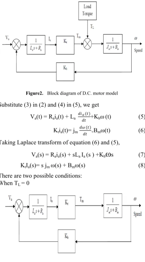
[image:2.595.314.552.156.585.2]In armature control of separately excited DC motors, the voltage applied to the armature of the motor is adjusted without changing the voltage applied to the field. Figure 1 shows a DC motor equivalent model.
Figure 1. D.C. motor model
Some useful relations are:
Va(t) = Raia(t) + La 𝑑𝑑𝑑𝑑𝑑𝑑𝑡𝑡𝑎𝑎(𝑡𝑡)+Eb (t) (1)
Eb (t) = Kbω(t) (2)
Tm(t) = Ktia(t) (3)
Tm(t) - TL(t) = jm 𝑑𝑑𝑑𝑑 (𝑡𝑡)𝑑𝑑𝑡𝑡 + Bmω(t) (4)
where Va = armature voltage (V), Ra = armature resistance (Ω), La = armature inductance (H), Ia = armature current (A), Eb= Back emf (V), ω = angular speed (rad/sec), Tm = motor torque (Nm), TL = load torque (Nm), θ = angular position of rotor shaft (rad), Jm = rotor inertia (kgm2), Bm = viscous friction coefficient (Nms/rad), Kt = torque constant (Nm/A), Kb = Back emf constant (Vs/rad). Figure 2 showing the basic block diagram of DC motor model including their transfer functions. Va is the input supply, TLis load torque and ω is angular speed. Figure2. Block diagram of D.C. motor model Substitute (3) in (2) and (4) in (5), we get Va(t) = Raia(t) + La 𝑑𝑑𝑑𝑑𝑑𝑑𝑡𝑡𝑎𝑎(𝑡𝑡)+Kbω(t) (5)
Ktia(t)= jm 𝑑𝑑𝑑𝑑 (𝑡𝑡)𝑑𝑑𝑡𝑡 +Bmω(t) (6)
Taking Laplace transform of equation (6) and (5), Va(s) = Raia(s) + sLa Ia (s ) +Kb
ω
s (7)KtIa(s)= s jm ω(s) + Bmω(s) (8)
[image:2.595.65.300.400.645.2]Figure 4. Block diagram D.C. motor model when Va= 0
Figure 4 shows the DC motor model when supply voltage (Va) is 0 and the transfer function of ω(s) is with respect to
TL(s).
Here, the relation between motor speed and load torque is given by the transfer function,
𝑑𝑑(𝑆𝑆) 𝑇𝑇𝐿𝐿(𝑆𝑆)=
−(𝐿𝐿𝑎𝑎𝑠𝑠+𝑅𝑅𝑎𝑎)
𝐿𝐿𝑎𝑎 𝐽𝐽𝑚𝑚 𝑠𝑠2 +(𝑅𝑅𝑎𝑎𝐽𝐽𝑚𝑚+𝐿𝐿𝑎𝑎𝐵𝐵𝑚𝑚)𝑠𝑠+(𝑅𝑅𝑎𝑎𝐵𝐵𝑚𝑚+𝐾𝐾𝑏𝑏𝐾𝐾𝑡𝑡) (10)
3. Speed Control Using Classical PID
Tuning Methods
The PID controller is the most common general purpose controller in the today’s industries. It can be used as a single unit or it can be a part of a distributed computer control system.
After implementing the PID controller, now we have to tune the controller; and there are different approaches to tune the PID parameters like P, I and D. The Proportional (P) part is responsible for following the desired set-point while the Integral (I) and Derivative (D) part account for the accumulation of past errors and the rate of change of error in the process or plant, respectively.
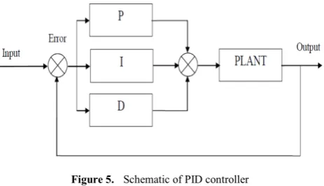
PID controller consists of three types of control i.e. Proportional, Integral and Derivative control
Figure 5. Schematic of PID controller
The system transfer function in continuous s-domain are given as
For
p
P
=
K
,
I K s
=
i/
andD
=
K s
d( )
ic p
K
dG s
P I D K
K s
s
= + + =
+
+
(11)( )
1
1
c p d
i
G s
K
T s
T s
=
+
+
(12)Where KP is the proportional gain, Ki is the integration
coefficient and Kd is the derivative coefficient.
Ti is known as the integral action time or reset time and Td
is the derivative action time or rate time.
There are various tuning strategies based on an open-loop step response. While they all follow the same basic idea, they differ in slightly in how they extract the model parameters from the recorded response, and also differ slightly as to relate appropriate tuning constants to the model parameters. There are different methods, the classic Ziegler-Nichols test, and Cohen- Coon test. Naturally if the response is not sigmoid or ‘S’ shaped and exhibits overshoot, or an integrator, then this tuning method is not applicable.
This method implicitly assumes the plant can be adequately approximated by a first order transfer function with time delay.
Gp =
𝐾𝐾𝑒𝑒
−𝜃𝜃𝑠𝑠
𝑇𝑇𝑠𝑠+1
(13)Where K is gain, θ is the dead time or time delay, and T is the open loop process time constant. Once we have recorded the open loop input/output data, and subsequently measured the times T and θ, the PID tuning parameters can be obtained directly from the given tables for different classical methods.
Figure 6. Block diagram of plant with variable output
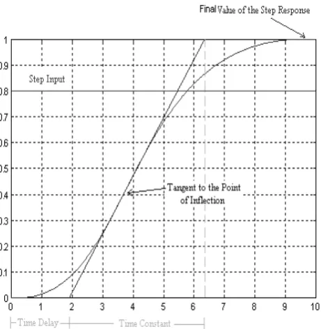
[image:3.595.63.295.537.670.2]Figure 7. System responses for first order time delay transfer function
From figure we can calculate the time delay (θ) and time constant (T) and maximum response (K=Dc gain), we can find the parameter of PID controller.
A: Ziegler-Nichols Tuning Method
The PID tuning parameters as a function of the open loop model parameters K, T and θ from the Process reaction curve derived by Ziegler-Nichols [2-5].
[image:4.595.312.551.212.358.2]They often form the basis for tuning procedures used by controller manufacturers and process industry. The methods are based on determination of some features of process dynamics. The controller parameters are then expressed in terms of the features by simple formulas. The method presented by Ziegler and Nichols is based on a registration of the open-loop step response of the system, which is characterized by two parameters. First determined, and the tangent at this point is drawn. The intersections between the tangent and the coordinate axes give the parameters T andθ. A model of the process to be controlled was derived from these parameters. This corresponds to modeling a process by an integrator and a time delay. Ziegler and Nichols have given PID parameters directly as functions of T andθ. The behavior of the controller is as can be expected. The decay ratio for the step response is close to one quarter. It is smaller for the load disturbance. The overshoot in the set point response is too large.
Table I. Ziegler Nichols open loop method
Controller Kp Ti Td
Ziegler-Nichols Method (Open
Loop)
P T/Kθ - -
PI 0.9T/Kθ θ/0.3 -
PID 1.2T/Kθ 2θ 0.5θ
B: Cohen-Coon Tuning Method
Cohen and Coon based the controller settings on the three parametersθ, T and K of the open loop step response. The main design criterion is rejection of load disturbances. The method attempts to position closed loop poles such that a quarter decay ration is achieved.
The PID tuning parameters as a function of the open loop model parameters K, T and θ from equation (14) as derived by Cohen-Coon:
Table II. Cohen Coon open loop method
4. Artificial Bee Colony Algorithm (Abc)
[6-10]
Dervis Karaboga and et. al presented the comparison results on the performance of the Artificial Bee Colony (ABC) algorithm for constrained optimization problems. The ABC algorithm has been firstly proposed for unconstrained optimization problems and showed that it has superior performance on these kinds of problems. In this paper, the ABC algorithm has been extended for solving constrained optimization problems and applied to a set of constrained problems [8].
In Bees Algorithm, the colony of artificial bees consists of three groups of bees: employed bees, onlookers and scouts. First half of the colony consists of the employed artificial bees and the second half includes the onlookers. For every food source, there is only one employed bee. In other words, the number of employed bees is equal to the number of food sources around the hive. The employed bee whose the food source has been abandoned by the bees becomes a scout. The position of a food source represents a possible solution to the optimization problem and the nectar amount of a food source corresponds to the quality (fitness) of the associated solution. The number of the employed bees or the onlooker bees is equal to the number of solutions in the population.
A: Implementation of Algorithm
Steps (pseudo-coding) to initialize the artificial BA: 1. Initialize the population of solutions xi,j, i = 1. . .S N, j
2. Evaluate the population. 3. Cycle=1
4. Repeat
5. Produce new solutions xi,j for the employed bees by
using (4) and evaluate them.
6. Apply the greedy selection process.
7. Calculate the probability values Pi,j for the solutions xi,j
by (4 & 3).
8. Produce the new solutions xi,j for the on looking from
the solutions xi,j selected depending on Pi,j
and evaluate them.
9. Apply the greedy selection process.
10. Determine the abandoned solution for the scout, if exists, and replace it with a new randomly
Produced solution xi,j by (4& 5).
11. Memorize the best solution achieved so far. 12. Cycle = Cycle+1.
13. Until Cycle = MCN.
B: Objective Function for Particle swarm optimization
function F= tightnes (kd, kp, ki)
T=tf([.023*kd .023*kp .023*ki],[.005 (.010015+.023*kd) (.000559+.023*kp).023*ki]);
S=stepinfo (T1); tr=S.RiseTime; ts=S.SettlingTime; Mp=S.Overshoot; Ess=1/(1+dcgain (T1));
[image:5.595.319.544.122.325.2]F= (1-exp (-0.5))*(Mp+Ess) +exp(-0.5)*(ts-tr); Table III. Parameter for ABC
Parameter Values
No. of Scout Bees 50
No. of Iterations 200
No. of Best selected patches 20
No. of Elite selected patches 10
The parameters used to describe the electrical and electromechanical systems are given below.
Table IV. Parameters of DC Motor
Parameter Values & Unit
R 1 Ω
Kb .023Kg-m/A
Kt .023V-s/rad
L 0.5H
Jm .01Kg-m-s2/rad
Bm .00003Kg-m-s/rad
C: ABC Flowchart
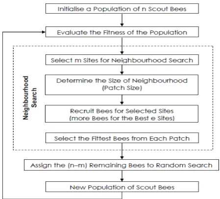
[image:5.595.316.549.417.521.2]The flowchart of the Artificial Bee Colony Optimization based PID control system is shown in figure 8.
Figure 8. Flowchart of Artificial Bee Colony Optimization
5. Simulink Model of DC Motor
The Simulink model of DC motor using is shown in Fig 8.
Figure 9. Simulink model of DC motor
[image:5.595.73.283.535.629.2]Figure 10. Simulink model of various tuning methods
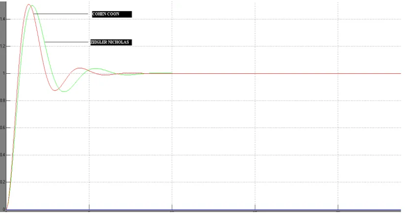
The Simulink model in Fig. 8 & 9 was simulated and the plots for various tuning method were observed. Fig. 10 and Fig. 11 show the Speed versus Time plot for conventional and bio inspired optimization method (ABC) respectively.
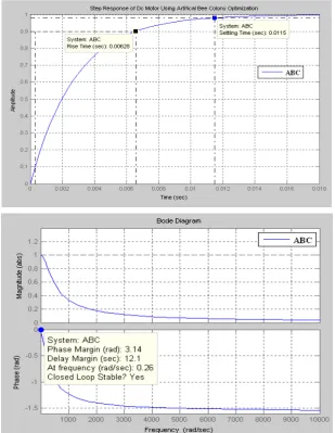
[image:6.595.101.515.378.596.2]Figure 12. Speed versus Time plot with reference speed for PID tuned with Artificial Bee Colony optimization (Step response)
Table V. Comparative analysis of various tuning
S.N Controller Kp Ki Kd Tr Ts Mp( %)
1 Z-N 1.385 1.69 0.28 0.592 7.328 43.43
2 C-C 1.545 1.55 0.23 .444 9.17 68.7
3 ABC 71.78 6.52 76.7 0.006 0.012 0
It can be seen from the above comparison table that while using the bio-inspired technique (Artificial Bee Colony Optimization ) the overshoots obtained is zero as compared to the case when the PID Controller is was tuned via conventional methods. The settling time is also lesser in case of the Artificial Bee Colony Optimization, also the rise time is reduced. The Artificial Bee Colony Optimization PID controller tends to approach the reference speed faster and has, comparatively, a zero overshoot. It can be observed
from Fig 11 and 12 that the Conventional PID controller have overshoot from the reference speed and attain a steady state with larger settling time.
6. Conclusion
[image:7.595.82.529.514.635.2]Optimization is best among the all methods which are used for tuning the parameter of PID controller for which settling time and rise is found to be less. The conventional controllers however are not recommended for higher order and complex systems as they can cause the system to become unstable. Hence, a heuristic approach is required for choice of the controller parameters which can be provided with the help of Bio inspired methods such as Artificial Bee Colony Optimization, where we can define variables in a subjective way.
Acknowledgments
This work was supported by Mr. Amit Gupta & Madan Mohan Mishra (SPMIT). Special Thanks to all faculty members of Electrical Engineering of United College of Engineering & Research, Allahabad India, Specially Head of Department Mr. Abdul Zeeshan & Mr. Vinod Kumar Vishwkarma, for their co-operation.
REFERENCES
[1] Akhilesh K. Mishra, Anirudha Narain, “Speed Control of Dc Motor Using Particle Swarm Optimization”, International Journal of Engineering Research and Technology Vol. 1 (02), 2012, ISSN 2278 - 0181
[2] Gopal K. Dubey, “Fundamentals of Electrical Drives”, Narosa Publishing House Pvt. Ltd., 2001, chap. 6.
[3] J.G. Ziegler, N.B. Nichols, “Optimization Setting for Automatic Controller”, Trans. ASME, Vol. 64,pp. 756-769, 1942.
[4] J. Kennedy, “The Particle Swarm: Social Adaptation of Knowledge”, Proceeding of the IEEE International Conference on Evolutionary Computation, ICEC1997, Indianapolis, pp. 303-308, 1997.
[5] Ozden Ercin and Ramazan Coban, “Comparison of the Artificial Bee Colony and the Bees Algorithm for PID Controller Tuning”, Innovations in Intelligent Systems and Applications (INISTA) IEEE conference, pp. 595-598, 2011.
[6] Benjamin C. Kuo, Farid Golnaraghi, 2009. Automatic Control Systems, 9th ed., John Wiley & Sons
[7] H. Gozde. C. Taplamacioglu and I. Kocaarslan, “Applications of Artificial Bees Colony Algorithm in an Automatic Voltage Regulator (AVR) System”, International Journal on Technical and Physical Problems of Engineering (IJTPE), Volume 2 Number 3, pp. 88-92, 2010.
[8] Gaowei YAN and Chuangqin LI, “An Effective Refinement Artificial Bee Colony Optimization Algorithm Based On Chaotic Search and Application for PID Control Tuning”, Journal of Computational Information Systems, Issue 7:9, pp. 3309-3316, 2011.
[9] I. J. Nagrath, M. Gopal, “Control Systems Engineering”, New Age International Publishers, 2007, chap. 3