TM
Hands-free navigation in VR environments by tracking the head
Sing Bing Kang
CRL 97/1
Cambridge Research Laboratory
The Cambridge Research Laboratory was founded in 1987 to advance the state of the art in both core computing and human-computer interaction, and to use the knowledge so gained to support the Company’s corporate objectives. We believe this is best accomplished through interconnected pur-suits in technology creation, advanced systems engineering, and business development. We are ac-tively investigating scalable computing; mobile computing; vision-based human and scene sensing; speech interaction; computer-animated synthetic persona; intelligent information appliances; and the capture, coding, storage, indexing, retrieval, decoding, and rendering of multimedia data. We recognize and embrace a technology creation model which is characterized by three major phases:
Freedom: The life blood of the Laboratory comes from the observations and imaginations of our
research staff. It is here that challenging research problems are uncovered (through discussions with customers, through interactions with others in the Corporation, through other professional interac-tions, through reading, and the like) or that new ideas are born. For any such problem or idea, this phase culminates in the nucleation of a project team around a well articulated central research question and the outlining of a research plan.
Focus: Once a team is formed, we aggressively pursue the creation of new technology based on
the plan. This may involve direct collaboration with other technical professionals inside and outside the Corporation. This phase culminates in the demonstrable creation of new technology which may take any of a number of forms - a journal article, a technical talk, a working prototype, a patent application, or some combination of these. The research team is typically augmented with other resident professionals—engineering and business development—who work as integral members of the core team to prepare preliminary plans for how best to leverage this new knowledge, either through internal transfer of technology or through other means.
Follow-through: We actively pursue taking the best technologies to the marketplace. For those
opportunities which are not immediately transferred internally and where the team has identified a significant opportunity, the business development and engineering staff will lead early-stage com-mercial development, often in conjunction with members of the research staff. While the value to the Corporation of taking these new ideas to the market is clear, it also has a significant positive im-pact on our future research work by providing the means to understand intimately the problems and opportunities in the market and to more fully exercise our ideas and concepts in real-world settings.
Throughout this process, communicating our understanding is a critical part of what we do, and participating in the larger technical community—through the publication of refereed journal articles and the presentation of our ideas at conferences–is essential. Our technical report series supports and facilitates broad and early dissemination of our work. We welcome your feedback on its effec-tiveness.
Hands-free navigation in VR environments by tracking the head
Sing Bing Kang
March 1997
Abstract
Conventional methods of navigating within a virtual reality environment involve the use of interfaces such as keyboards, hand-held input devices such as joysticks, mice, and trackballs, and hand-worn data gloves. While these devices are mostly adequate, they are rather obstrusive and require some amount of training to use. Researchers have begun investigation into interfaces that have the capability to interpret human gestures visually.
c Digital Equipment Corporation, 1997
This work may not be copied or reproduced in whole or in part for any commercial purpose. Per-mission to copy in whole or in part without payment of fee is granted for nonprofit educational and research purposes provided that all such whole or partial copies include the following: a notice that such copying is by permission of the Cambridge Research Laboratory of Digital Equipment Corpo-ration in Cambridge, Massachusetts; an acknowledgment of the authors and individual contributors to the work; and all applicable portions of the copyright notice. Copying, reproducing, or repub-lishing for any other purpose shall require a license with payment of fee to the Cambridge Research Laboratory. All rights reserved.
CRL Technical reports are available on the CRL’s web page at http://www.crl.research.digital.com.
Digital Equipment Corporation Cambridge Research Laboratory One Kendall Square, Building 700
CONTENTS i
Contents
1 Introduction 1
1.1 Relevant work . . . 1 1.2 The “hands-off” navigation approach . . . 3 1.3 Organization of document . . . 3
2 2-D perspective tracking 5
2.1 Decomposition of full 2-D perspective matrix . . . 6
3 Affine camera 7
4 Using affine tracking to determine limited head pose 9
5 Controlling the view 11
6 Results 12
7 Discussion 15
ii LIST OF FIGURES
List of Figures
1 Concept of hands-free navigation. . . 4 2 Effect of tilt ( ) on perceived rotation: (a) =
=
2(top view), and (b) between0 and
=
2(view from an angle above). . . 9 3 Starting tilt 0 of face (represented as planar patch) relative to the camera viewingdirection.
y
true is the true facial height whiley
0 is the initial apparent facial height. Again we assume insignificant perspective effects. . . 11 4 Effect of moving along the camera axis.
f
is the camera focal length,L
is thelength of the object,
z
0 is the reference location,zis the change in object location, andh
0andh
are the projected images lengths (in pixels) of the object at positionsz
0 and (z
0
+
z)respectively. . . 12 5 Face tracking results: (a) Reference face; (b) Face turned to the left of camera; (c)Face turned to the right of camera; (d) Face moved closer to the camera; (e) Face turned upwards; (f) Face turned downwards. The monochrome subimage of the face is the computed edge strength image. . . 13 6 Response by viewer to changes in face pose (see Figure 5: (a) Initial view; (b)
View rotated to the left; (c) View rotated to the right; (d) View moved closer; (e) View rotated upwards; (f) View rotated downwards. . . 14 7 Pose parameter against time for head motion in predominantly X and then Y image
plane directions. (a) and (b) are the unfiltered and filtered versions respectively. . . 15 8 Pose parameter against time for predominantly head tilting motion. (a) and (b) are
the unfiltered and filtered versions respectively. . . 16 9 Pose parameter against time for head motion that includes moving towards and
1
1
Introduction
Conventional methods of navigating within a virtual reality environment involve the use of in-terfaces such as keyboards, hand-held input devices such as joysticks, mice, and trackballs, and hand-worn data gloves. While these devices are mostly adequate, they are rather obstrusive and require some amount of training to use. In addition, because of the constant physical use and ma-nipulation, they either have limited life or require some degree of maintenance. Researchers have begun investigation into natural interfaces that are intuitively simple and unobstrusive to the user. By natural, we mean communication by way of human gestures and/or speech.
The proposed approach is designed to address the problem of navigating within a virtual envi-ronment without the use of keyboards, hand-held input devices, or data gloves. The approach that we take is to track the pose (i.e., translation and orientation) of the face and use that information to move and orient the virtual environment accordingly. This method of navigating the virtual environment is very intuitive and easy. Part of the novelty of the approach is the tracking of the entire face image without the use of any geometric face model. The simplicity of the approach allows fast tracking without using specialized image processing boards. The speed of face tracking currently achieved is 4 frames per second on a DEC AlphaStation 600 with an image patch size of 98x80 pixels.
1.1
Relevant work
Approaches to controlling interaction in a virtual environment have been mostly limited to using hand gestures for games (using a hand worn device such as a Mattel glove) or for manipulating virtual objects using a dataglove (e.g., [18]).
Other work that are relevant to this approach relate to face tracking. In [3], the full face is tracked using a detailed face model that relies on image intensity values, deformable model dy-namics, and optical flow. This representation can be used to track facial expressions. Due to its complexity, processing between frames is reported to take 3 seconds each on a 200 MHz SGI ma-chine. Initialization of the face model on the real image involves manually marking face locations, and takes 2 minutes on the same SGI machine.
2 1 INTRODUCTION
the nose, and corners of the mouth. As described in the paper, these features are manually chosen. In [8], 3-D head orientation is estimated by tracking five points on the face (four at the eye corners and one at the tip of the nose). Again the facial features are selected by hand.
Also relevant is [14], which describes a real-time (20 frames per second) facial feature tracking system based on template matching. The system includes the DataCube real-time image processing equipment. The face and mouth areas are extracted using color histogramming while the eyes are tracked using sequential template matching. An application cited is the visual mouse, which emulates the functionality of the physical mouse through eye position (cursor movement) and mouth shape change (clicking operation). Again this system tracks specific features of the face; it is not clear if this form of tracking (sequential) is stable over time and whether reliable face orientation can be derived from so few features.
In their work on facial image coding, Li et al. [10] use a 3-D planar polygonized face model and assume 3-D affine motion of points. They track the motion of the face model (both local and global) using optic flow to estimate the facial action units (based on the facial action coding system, or FACS [4]). A feedback loop scheme is employed to minimize the error between the synthetically generated face image based on motion estimates and the true face image. However, they have to estimate the depth of the face, assumed segmented out, in the scene. The feature node points of the face model are manually adjusted to initially fit the face in the image. No timing results were given in their paper.
Azarbayejani et al.’s [1] system tracks manually picked points on the head, and based on re-cursive structure from motion estimates and Extended Kalman filtering, determine the 3-D pose of the head. The cited translation and rotation error, with respect to the Polhemus tracker estimates, are 1.67 cm and 2.4 respectively. The frame rate achieved is 10 frames per second. Their system requires local point feature trackers.
1.2 The “hands-off” navigation approach 3
1.2
The “hands-off” navigation approach
Our concept of “hands-off” navigation is depicted in Figure 1. The camera is mounted in front and above the user; it views the user’s face from a tilted angle. The system requires a reference face image, and this image is captured for initialization. The reference face image is that of the user in a neutral pose, where he/she is facing directly ahead below the camera. To determine the head trans-lation and orientation, the face tracker warps the reference face image to minimize the difference between the warped reference face image and the current face image. This is equivalent to using the reference face image as a globally deformable template. The warping matrix transformation is then decomposed to yield the face translation and orientation. Subsequently, the view point of the 3-D virtual environment changes accordingly.
The software is written in C, and is run in a DEC AlphaStation 600. The 3-D virtual envi-ronment viewer used for our system is VRweb, which is originally developed by the Institute for Information Processing and Computer Supported New Media (IICM), Graz University of Technol-ogy, in Austria1. We customized it to allow TCP/IP communication with the face tracker.
In navigating a virtual environment, it is very likely that the user would not want to rotate the scene about the viewing direction. Hence we adopt this convenient assumption, and disable control of rotational motion about the viewing axis (i.e., rotation about
t
zvector in Figure 1).This research is done in connection with the Smart Kiosk project at Cambridge Research Lab, Digital Equipment Corp. [20]. The Smart Kiosk can be considered as an enhanced version of the Automatic Teller Machine, with the added capability of being able to interact with the user through body tracking, and gesture and speech recognition. The “hands-off” capability would enable the Smart Kiosk to allow the user to navigate the local virtual environment as an information dispensing appliance. The local virtual environment could be created using either direct range data or stereo from multiple real images [9].
1.3
Organization of document
We first review the most general global motion tracking, namely full 2-D perspective tracking in Section 2. Here we also describe how 2-D motion matrix is decomposed directly into various motion parameters such as translation, magnification, and skew. Since the face is assumed to be relatively far away from the camera, we can assume an affine model rather than a full 2-D perspective model. Section 4 describes how the motion parameters derived from Section 2 can be used to extract head translation and orientation. Results are shown in Section 6, followed by
4 1 INTRODUCTION
Digitizer
Face tracker
3-D virtual
environment viewer image
position and orientation
camera
tx ty
tz rx
r y
Tracked head motions:
rx r y ty tz tx
,
[image:10.612.94.515.180.548.2], , : translation in x, y, and z respectively : rotation about x and y axis respectively
5
discussion on the implication of the method in Section 7. Finally, we summarize the approach in Section 8.
2
2-D perspective tracking
The approach in tracking is the same as the approach for image registration described in [13, 16], i.e., to directly minimize the discrepancy in intensities between pairs of images after applying the transformation we are recovering. This has the advantage of not requiring any easily identifiable feature points, and of being statistically optimal once we are in the vicinity of the true solution [17]. The technique minimizes the sum of the squared intensity errors
E
= Xi
I
0(
x
0 iy
0i);
I
(x
iy
i)] 2 = X ie
2 i (1)subject to the constraint
x
0 i =m
00x
i+
m
01
y
i+
m
02
m
20x
i+
m
21
y
i+ 1
y
0 i =m
10x
i+
m
11
y
i+
m
12
m
20x
i+
m
21
y
i + 1:
(2)The objective function
E
is applied over the region of interest.The minimization of
E
is done using the Levenberg-Marquardt iterative non-linear minimiza-tion algorithm [12]. This algorithm requires the computaminimiza-tion of the partial derivatives ofe
i with respect to the unknown motion parametersfm
00
:::m
21g. These are straightforward to compute, i.e.,
@e
i@m
0 =x
iD
i@I
0@x
0::: @e
i@m
7=;
y
iD
ix
0 i@I
0@x
0 +y
0 i@I
0@y
0 ! (3)where
D
i is the denominator in (2), and (@I
0
=@x
0@I
0=@y
0)is the image intensity gradient of
I
0 at (x
0 i
y
0i). From these partials, the Levenberg-Marquardt algorithm computes an approximate Hessian matrix
A
and the weighted gradient vectorb
with componentsa
kl=2 Xi
@e
i@m
k@e
i@m
lb
k =;2 Xi
e
i@e
i@m
k (4)and then updates the motion parameter estimate
m
by an amountm
=(A
+I
) ;1b
, where
is a time-varying stabilization parameter [12]. The advantage of using Levenberg-Marquardt over straightforward gradient descent is that it converges in fewer iterations.6 2 2-D PERSPECTIVE TRACKING
at each level. We set the number of resolutions to be 3 and the number of iterations per level to be 3.
2.1
Decomposition of full 2-D perspective matrix
Given the full 2-D perspective matrix, we can decompose it into the following warping parameters:
center point or displacement
t
x andt
y (inx
andy
directions respectively) rotation angleI(about the viewing axis)zoom factor aspect ratio
a
skew factors
pinch parameters
xandy(inx
andy
directions respectively) Definer
x =a
andr
y =a
(5)and let
s
=sinI andc
=cosI.The 2-D perspective matrix (which is first scaled such that
m
22= 1) can be decomposed as follows:
0
B B @
m
00m
01m
02m
10m
11m
12m
20m
21 1 1 C C A = 0 B B @1 0
t
x 0 1t
y0 0 1
1 C C A 0 B B @
c
;s
0s c
00 0 1
1 C C A 0 B B @
r
x 0 0 0r
y 00 0 1
1 C C A (6) 0 B B @
1
s
00 1 0
0 0 1
1 C C A 0 B B @
1 0 0
0 1 0
x y 1 1 C C A = 0 B B @c r
x+xt
xc sr
x;s r
y +yt
xt
xs r
x+xt
ys sr
x+c r
y +yt
yt
y x y 11
C C A
7
to be true, even with face images as large as about 100 100. As a result, we use instead an approximation of the 2-D perspective model, namely the 2-D affine model.
For the 2-D affine case, we set
m
20=
m
21
=0and
x =y =0, giving 0B B @
m
00m
01m
02m
10m
11m
120 0 1
1 C C A = 0 B B @
c r
xc sr
x;s r
yt
xs r
xs sr
x+c r
yt
y0 0 1
1
C C A
(7)
Next, we describe the affine camera, and show the cases when 2-D affine transformation is valid.
3
Affine camera
The 2-D affine transformation of the image is applicable for the affine camera. The affine camera has the projection matrix of the form
Taffine = 0
B B @
T
00T
01T
02T
03T
10T
11T
12T
130 0 0 1
1 C C A = 0
@
M
m
0
T 11
A (8)
If
p
is the 3-D point in space andu
is the corresponding affine projection, thenu
=M
p
+m
(9)In the affine camera model, all epipolar lines are parallel, and the epipoles are located at infinity in the image planes. This camera model is a generalization of the scaled orthographic (also known as weak perspective or paraperspective) camera model, which can be used as a good approximation if the change in relative object depth is small compared to its distance to the camera. For a fuller description of the affine and scaled orthographic camera models, the reader is encouraged to refer to the Appendix of [11].
As shown in [16], full 2-D perspective image transformation can only be used in cases of planar surfaces using the perspective camera model and rotation about the camera optic center. The 2-D affine image transformation can be used only in the cases of planar surfaces and translation under the affine camera model. To see this, we use the derivation similar to [15].
Let 3-D point
p
be a point on a planar patch whose unit normal isn
^. Let alson
^?1 and ^
n
?2be the other two unit vectors that, withn
^, form the orthonormal bases of<3
. Thus
p
can be specified asp
=n
^ ?1+
n
^ ?28 3 AFFINE CAMERA
Note that
p
lies on the plane whose equation isp
n
^ =,being a constant. Let alsoR
be the33rotation matrix such thatR
n
^ = 0 B B @ 0 0 1 1 C C AR
n
^ ?1= 0 @
g
1 0 1 AR
n
^?2 = 0 @
g
2 0 1 A (11) From (9),u
=MR
;1R
p
+
m
(12)=
M
R0
@
g
1+
g
21
A
+
m
where
M
R =MR
;1. We now partition
M
Ras(B
jb
), after which we can rewrite (12) asu
=B
(g
1+
g
2)+
b
+m
(13)=
B
(g
1+
g
2)+
b
with
b
=b
+m
. Note that the only variables on the right hand side of (13) that depend on 3-D point location on the plane areand.Similarly, for another affine camera, we have
u
0=
B
0 (
g
1 +
g
2 )+
b
0 +
m
0 (14) =B
0 (g
1 +
g
2 )+
b
0
Eliminating(
g
1+
g
2)from (13) and (14) yields
u
0=;
u
+ (15)where; =
B
0B
;1and
=b
0;;
b
. Henceu
0is an affine transformation of
u
for points on a plane.Showing the applicability of the 2-D affine transformation under translation is trivial. If the 3-D translation is
p
, thenu
0=
M
(p
+p
)+m
=u
+M
p
(16)9
x y
x y
(a) (b)
θ θ(α,φ)
α
q
p
p’ q’
x z
x z
(c) (d)
q p p’
[image:15.612.71.543.111.254.2]q’
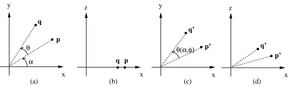
Figure 2: Effect of tilt ( ) on perceived rotation: (a) =
=
2(top view), and (b) between 0 and=
2(view from an angle above).4
Using affine tracking to determine limited head pose
We have shown in the preceding section that 2-D affine transformation is valid for planar surfaces with an affine camera model. This is a good approximation if the face is far away enough from the camera. This has the effect of rendering the relative depth change in the face to be insignificant relative to the distance of the face from the camera. The face can then be approximated as a planar surface.
We capitalize on the decomposition of the 2-D affine matrix to determine head pose (location and orientation). However, in navigating a virtual environment, it is very likely that the user would not want to rotate the scene about the viewing direction. Hence we adopt this convenient assumption, and disable control of rotational motion about the viewing axis.
To keep the camera relatively unobstrusive to the user, it is better to position it higher up above the monitor and allow it to track the user’s head from that location at a tilted angle. This location has a convenient side-effect; head rotations to either side map result in rotations about the viewing axis, which can be easily obtained from the affine matrix decomposition.
To see this, we consider viewing the head from the top (Figure 2(a)) and viewing the head at a tilted angle (Figure 2(b)). We assume that perspective effects are negligible. The point
p
has rotated by an angle toq
. Seen from an angle, the corresponding points arep
0and
q
0, and the perceived rotation angle is
( ); being the original angle subtended byp
with respect to the x-axis and is the tilt angle about the x-axis.10 4 USING AFFINE TRACKING TO DETERMINE LIMITED HEAD POSE
Hence we get
p
= 0 @ cos sin 1 Aq
= 0 @cos (
+) sin(+)1 A
p
0 = 0 @ cos sinsin1 A
q
0 = 0 @cos(
+) sin(+)sin1
A (17) From (17), we can easily recover
( ): ( )=cos ;10
B B @
cos
cos(+)+sinsin(+)sin 2 rcos
2
(
+)+sin 2(
+)sin 2 cos 2 +sin 2 sin 2 1 C C A (18)For the case where the starting head pose is with the head facing horizontally below the camera (which we also assume), i.e.,
==
2, from (18) we get (2
)=I =cos ;1cos
sin p sin 2 +cos 2 sin 2 ! (19)To track the location of the head, we simply track the center of the affine patch (given by
t
x andt
y). Motion in the forward/backward direction is given by the amount of zoom . Due to the camera tilt, moving the head ahead has the undesirable effect of giving an image displacement in the y direction as well. The fix is to disable all other motion while zooming is detected.If we know the tilt (from (22)), the true head rotation is then
=tan ;1(tan
Isin ) (20)Finally, the head tilt is determined from the amount of y magnification
r
y; because the camera is situated at a vertical angle with respect to the head, tilting up to face the camera results in largerr
y (y extent is larger than usual, hence greater than 1), while tilting the head down has the opposite effect. In the absence of all other motion parameters, the apparent facial height is (see Figure 3)y
=r
yy
0=
r
yy
truecos0 (21)
Hence the face tilt angle with respect to the camera is given by
=cos ;1
y
y
true ! =cos ;1(
r
ycos 0) (22)
To determine 0, we can apply a “calibration” technique in which the user tilts his/her head up and down once. The system keeps track of the maximum value of
r
y, sayr
ymax. Then11
Camera viewing
direction
Starting tilt
of face
τ
0∆
y
true [image:17.612.152.463.104.215.2]∆
y
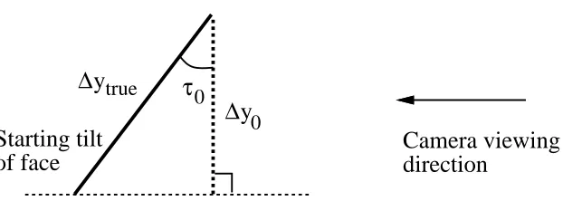
0Figure 3: Starting tilt 0 of face (represented as planar patch) relative to the camera viewing di-rection.
y
true is the true facial height whiley
0 is the initial apparent facial height. Again we assume insignificant perspective effects.
We are interested in the face tilt angle with respect to the environment rather than with respect to the camera. Hence, the actual tilt angle used to control the orientation of the virtual environment is the displaced tilt angle given by
0
= ;
0 =cos
;1
(
r
ycos 0);
0 (24)
5
Controlling the view
Even though we are able to extract the 5 pose parameters of the face, we are faced with the problem of using them to control the viewing of the virtual reality environment. One simple way would be to directly use the pose parameters to determine the absolute position and orientation of the viewpoint. However, this limits the viewpoint selection to the pose that the face can assume within the camera viewing space.
12 6 RESULTS
camera center
image plane
f
L L
h
z0
z δ
0
[image:18.612.153.460.112.256.2]h
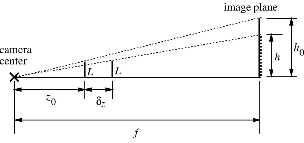
Figure 4: Effect of moving along the camera axis.
f
is the camera focal length,L
is the length of the object,z
0 is the reference location,zis the change in object location, andh
0 andh
are the projected images lengths (in pixels) of the object at positionsz
0 and(
z
0+
z)respectively. To minimize the possibility of sudden jumps in consecutive viewpoints, we employ a simple Kalman-based filter to smooth the motion trajectory (see, for example, [7]).While the orientation angles of tilt and pan can be directly used, we still need the translational scaling factors in x, y, and z. These are dependent on the relative scaling of the virtual environment. However, converting amount of zoom (see Section 2.1) to change in depth
z
is less direct. From Figure 4, letz
0 be the reference depth location of the face. If the face has moved byz, then by similarity of triangles, we haveL
z
0=
h
0f
andL
z
0 +z=
h
f
(25)with
h
=h
0. Thus,
L
z
0+
z =h
0
f
=Lz
0(26) from which
z =z
01 ;1
!
(27)
6
Results
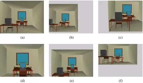
[image:18.612.81.546.457.631.2]13
(a) (b) (c)
[image:19.612.71.538.222.494.2](d) (e) (f)
14 6 RESULTS
(a) (b) (c)
[image:20.612.73.539.231.503.2](d) (e) (f)
15
0 20 40 60 80 100
Frame
−60.0 −40.0 −20.0 0.0 20.0 40.0
Pose parameters X
Y Z Pan Tilt
0 20 40 60 80 100
Frame
−60.0 −40.0 −20.0 0.0 20.0 40.0
Pose parameters X
Y Z Pan Tilt
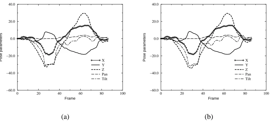
[image:21.612.84.521.116.322.2](a) (b)
Figure 7: Pose parameter against time for head motion in predominantly X and then Y image plane directions. (a) and (b) are the unfiltered and filtered versions respectively.
Examples of plots of X, Y, Z, Pan, and Tilt against the frame number (both before filtering and after filtering) are shown in Figures 7-9. X and Y are given in pixels, Z is the scaled change in depth as given in (27), and Pan and Tilt are in degrees. As can been seen, the Kalman filter has the effect of smoothing the pose parameters.
7
Discussion
The face is obviously not planar, and the most robust approach of tracking the face would probably be to employ a properly initialized full 3-D face model on the image with a perspective camera model, as used by [3]. However, the face model initialization is not trivial, nor is it fast. The method described in this article sacrifices some accuracy for ease of initialization and speed of tracking by making the basic assumption that the face is far enough from the camera. In our application of navigating a virtual environment, absolute accuracy is not necessary. This distance assumption allows the scaled orthography camera model to be used, and the face to be assumed relatively planar.
16 7 DISCUSSION
0 10 20 30 40 50
Frame
−60.0 −40.0 −20.0 0.0 20.0 40.0
Pose parameters X
Y Z Pan Tilt
0 10 20 30 40 50
Frame
−60.0 −40.0 −20.0 0.0 20.0 40.0
Pose parameters X
Y Z Pan Tilt
[image:22.612.83.520.123.332.2](a) (b)
Figure 8: Pose parameter against time for predominantly head tilting motion. (a) and (b) are the unfiltered and filtered versions respectively.
0 20 40 60 80 100
Frame
−60.0 −40.0 −20.0 0.0 20.0 40.0
Pose parameters X
Y Z Pan Tilt
0 20 40 60 80 100
Frame
−60.0 −40.0 −20.0 0.0 20.0 40.0
Pose parameters X
Y Z Pan Tilt
(a) (b)
[image:22.612.81.521.421.627.2]17
is more appropriate but more unstable, while using pure 2-D rigid transform lacks the important parameters of scaling and skewing. As shown by our results, the 2-D affine model works well and is a good compromise.
Depending on the speed of head motion, the tracker pose output trajectory can be a little jerky. This is due to image noise and limited speed of convergence in image registration. To reduce the severity of this problem, we use the Kalman filter; it does help to produce a smoother trajectory of navigation.
8
Summary
In summary, the key features of our approach to “hands-off” navigation in virtual reality environ-ments are:
Only one camera is used, and its calibration is not necessary.
Initialization is done by just taking a snapshot of the face in a neutral pose (facing directly ahead below the camera). This reference face snapshot is used to track the pose of the face.
Tracking and pose determination is done using all the pixels in the image patch. This is considerably more robust than tracking specific small local features as is usually done [6, 8, 14]. To reduce dependency of the approach to illumination, we use the edge strength image rather than the direct intensity image. A comparative study of face recognition approaches seems to favor using templates as compared to using specific geometrical face features [2]. At any given instant of time, the reference face image that has been taken during the initial-ization step is warped so as to minimize its intensity difference with the current face image. The warping transformation matrix is then decomposed to yield both position and orientation of the face. This is equivalent to deformable template matching with global motion.
A geometric face model is not required. This is a major departure from most existing meth-ods of tracking the face [3, 5, 6, 8, 14, 19]. As such, there are no complicated initialization steps required of this approach.
18 REFERENCES
The face, rather than the articulated hand, is being tracked; tracking the articulated hand and recognizing hand gestures is considerably more complicated and possibly error-prone.
We have also shown some results of virtual reality environment navigation by tracking the head.
Acknowledgments
The Kalman Filter code used in the system was implemented by Maria Loughlin.
References
[1] A. Azarbayejani, T. Starner, B. Horowitz, and A. Pentland. Visually controlled graphics.
IEEE Transactions on Pattern Analysis and Machine Intelligence, 15(6):602–605, June 1993.
[2] R. Brunelli and T. Poggio. Face recognition: Features versus templates. IEEE Transactions
on Pattern Analysis and Machine Intelligence, 15(10):1042–1052, October 1993.
[3] D. DeCarlo and D. Metaxas. The integration of optical flow and deformable models with ap-plications to human face shape and motion estimation. In IEEE Computer Society Conference
on Computer Vision and Pattern Recognition (CVPR’96), pages 231–238, San Francisco, CA,
June 1996. IEEE Computer Society.
[4] P. Ekman and W. V. Friesen. Manual for the Facial Action Coding System. Palo Alto: Consulting Psychologists, 1977.
[5] I. A. Essa and A. Pentland. A vision system for observing and extracting facial motion pa-rameters. In IEEE Conf. on Computer Vision and Pattern Recognition, pages 76–83, Seattle, Washington, 1994.
[6] A. Gee and R. Cipolla. Estimating gaze from a single view of a face. In 12th IAPR
In-ternational Conference on Pattern Recognition, volume I, pages 758–760, Jerusalem, Israel,
1994.
REFERENCES 19
[8] T. Horprasert, Y. Yacoob, and L. S. Davis. Computing 3-d head orientation from a monocular image sequence. In 2nd International Conference on Automatic Face and Gesture
Recogni-tion, pages 242–247, Killington, VT, 1996.
[9] S. B. Kang and R. Szeliski. 3-D scene data recovery using omnidirectional multibaseline stereo. In Proc.s IEEE Computer Society Conference on Computer Vision and Pattern
Recog-nition, pages 364–370, June 1996.
[10] H. Li, P. Roivainen, and R. Forchheimer. 3-D motion estimation in model-based facial image coding. IEEE Transactions on Pattern Analysis and Machine Intelligence, 15(6):545–555, June 1993.
[11] J. L. Mundy and A. Zisserman, editors. Geometric Invariance in Computer Vision. MIT Press, 1992.
[12] W. H. Press, B. P. Flannery, S. A. Teukolsky, and W. T. Vetterling. Numerical Recipes in C:
The Art of Scientific Computing. Cambridge University Press, Cambridge, England, second
edition, 1992.
[13] J. Rehg and A. Witkin. Visual tracking with deformation models. In IEEE International
Con-ference on Robotics and Automation, pages 844–850, Sacramento, California, April 1991.
IEEE Computer Society Press.
[14] H. Sako, M. Whitehouse, A. Smith, and A. Sutherland. Real-time facial-feature tracking based on matching techniques and its application. In 12th IAPR International Conference on
Pattern Recognition, volume II, pages 320–324, Jerusalem, Israel, 1994.
[15] L. S. Shapiro, A. P. Zisserman, and M. Brady. Motion from point matches using affine epipo-lar geometry. Technical Report OUEL 1994/93, University of Oxford, Robotics Research Group, 1993.
[16] R. Szeliski. Image mosaicing for tele-reality applications. In IEEE Workshop on
Applica-tions of Computer Vision (WACV’94), pages 44–53, Sarasota, Florida, December 1994. IEEE
Computer Society.
[17] R. Szeliski and J. Coughlan. Hierarchical spline-based image registration. In IEEE Computer
Society Conference on Computer Vision and Pattern Recognition (CVPR’94), pages 194–201,
20 REFERENCES
[18] T. Takahashi and H. Ogata. Robotic assembly operation based on task-level teaching in virtual reality. In IEEE International Conference on Robotics and Automation, pages 1083–1088, Nice, France, 1992.
[19] T. Tsukamoto, C.-W. Lee, and S. Tsuji. Detection and pose estimation of human face with synthesized image models. In 12th IAPR International Conference on Pattern Recognition, volume I, pages 754–757, Jerusalem, Israel, 1994.
TM
Hands-free
na
vigation
in
VR
en
vir
onments
b
y
trac
king
the
head
Sing
Bing
Kang
CRL
97/1
March