EFFICIENT ENERGY BASED CONGESTION CONTROL
SCHEME FOR MOBILE AD HOC NETWORKS
1S.SHEEJA, 2DR.RAMACHANDRA V PUJERI
1
Research Scholar, Bharathiar University, Coimbatore. 2
Vice-Principal, KGiSL Institute of Technology, Saravanampatti, Coimbatore. E-mail: [email protected], [email protected]
ABSTRACT
In recent years, MANET is the popular and growing network used in various applications. Here the mobile nodes are randomly moving without any access point. Due to mobility of nodes, energy consumption of the network goes higher. More energy consumption occurs due to retransmission of packets and occurrence of packet loss unlimitedly. So the main goal of the network is to ensure more energy efficiency. To provide minimum energy consumption and avoiding more congestion, energy consumption model and multipath routing scheme is needed in networks. In this research paper, we developed an Efficient Energy based Congestion Control Scheme (EECCS) for congestion avoidance and to improve energy efficiency of the mobile nodes. Here the cross layer design is deployed to improve the network performance. The multipath routing is focussed to avoid congestion and to increase network lifetime. We also demonstrated the energy consumption mathematical model to illustrate the node’s minimum energy consumption level in the network. Probability of the retransmission of packets is reduced with the help of calculating the energy level of data and acknowledgment packets. By using extensive simulation, the proposed scheme achieves minimum energy consumption, low packet loss ratio, high packet delivery ratio, low end to end delay and overhead than our previous schemes like ECAS, CLSMRSCA.
Keywords: MANET, Probability Of Retransmission Of Packets, Cross Layer Design, Multipath Routing, Energy Consumption Model , Packet Delivery Ratio, Packet Loss Ratio, End To End Delay, Overhead And Network Lifetime
1
INTRODUCTION1.1 Mobile Ad Hoc Networks (MANET)
Mobile Ad hoc Networks (MANET) consist of wireless nodes that form a communications network among themselves without a fixed infrastructure. Topology changes in MANET usually occur due to the mobility of a participating node or breakdown of a node due to loss of energy in that node. These dynamic conditions disrupt the smooth communication between needs in the network. Conceptually, in MANET, a node may either function as an end node or as a router forwarding data packets between end nodes. Hence the fitness of the node in terms of available energy in the node becomes an important issue during the selection of an intermediate node
1.2 Need for Cross layer Design in MANET
The requirement of Cross Layer design in ad hoc networks is given below.
1.2.1 Adaptive and self-organization
Network protocols for MANETs must be adaptive to many factors to effectively support fair sharing of devices and resources and to hide the system dynamics to the upper layers. The system dynamics include a wide range of communication conditions a wireless node can experience inside a MANET, including changing topology, shared medium contention, varying traffic patterns and distributions.
Energy Conservation
wireless device when the node is idle. At the network layer, the route selection process should be performed by reducing the end-to end power needed to forward the packet. If the network layer may have access to energy information, battery-level metrics can be used in the routing process.
1.3 Congestion Control in MANETs
Congestion control is the main problem in ad-hoc networks. Congestion control is associated to controlling traffic incoming into a telecommunication network. To avoid congestive crumple or link capabilities of the intermediate nodes and networks and to reduce the rate of sending packets congestion control is used extensively. Congestion control and dependability mechanisms are combined by TCP to perform the congestion control without explicit feedback about the congestion position and without the intermediate nodes being directly intermittent.
Packet failure in MANETs is primarily caused due to obstruction. The packet loss can be condensed by involving congestion control over a mobility and failure adaptive routing protocol at the network layer. The congestion non-adaptive routing protocols, leads to the following difficulties: Extensive delay, More Overhead, Heavy packet losses
2
RELATED WORKImran Chowdhury et.al [1] proposed an energy efficient and cooperative congestion control protocol (EECCCP) for cooperative multicasting in mobile ad hoc networks. It overcomes the disadvantages of existing multicast congestion control protocols such as AODV and EERCCP. In the first phase it builds a cooperative multicast tree rooted at the source, by including the nodes with higher residual energy towards the receivers. In the second phase an admission control scheme in which a cooperative multicast flow is admitted or rejected depending upon on the output queue size. Finally tests whether the relay node has the potential path to the required destination, if not then choose another node which has the second highest residual energy as a new relay node.
K.Srinivas and A.A. Chari proposed [2] Energy Efficient Cross Layered Congestion Detection and Control Routing Protocol to deliver an energy efficient mechanism to quantify the degree of congestion at victim node with maximal accuracy. The proposed model involves controlling of congestion in two steps with effective energy efficient congestion detection and optimal
utilization of resources. Packet loss in network routing is primarily due to link failure and congestion. Most of the existing congestion control solutions do not possess the ability to distinguish between packet loss due to link failure and packet loss due to congestion.
Appaji and Sreedhar [3] proposed a cross layered routing topology in short CRT to improve the congestion detection and handling strategy. The CRT is Mac, application and physical layer centric in particular. With the motivation gained from CRT, here in this paper we propose a cross layered power conserved routing topology (CPCRT) for mobile ad hoc networks. The goal is to improve transmission performance by distinguishing between packet loss due to link failure and arbitrary loss of packets along with power conservation that used for packet transmission.
Suryaprakash Reddy et.al [4] proposed the routing algorithm called Energy efficient Ordered Congestion Control using Cross layer support. In this article, it is refined the OCC to gain the ability of energy conservation in congestion discovery. In this effort it attempts to limit the role of MAC layer to detect link failure and developed a new strategy to detect the congestion at a relay node level and path level.
Vishnu kumar [5] proposed an Congestion and Power Control Technique Based on Agent in MANET. The mobile agent from source starts forwarding the data packets through the path which has minimum cost and congestion. The status of every node is composed and lastly it is delivered to destination node. In power control technique, the nodes are selected based on the power level.
Rajesh babu et.al [6] proposed to develop an Energy Efficient Secure Authenticated Routing Protocol (EESARP) for mobile adhoc networks, which uses a lightweight, attack resistant authentication mechanism. The protocol provides efficient security against route discovery attacks using hop-by-hop signatures. It also uses an efficient node selection mechanism which maximizes network life time and minimizes delay.
loss. After detecting losses due to link failure, it should adjust RTO for reconstructed route by comparing its capabilities with broken route using available information in transport layer.
V. Thilagavathe and Dr. K. Duraiswamy [8] proposed the a cross-layer based technique to overcome congestion that occurs in MAC and transport layer in MANET. The proposed technique was applied over a Adhoc On demand Multipath Reliable and Energy Aware QoS Routing Protocol (AOMP-REQR). If source receives congestion status information from both MAC and transport layer simultaneously for the same route, then congestion free route can be established for transmission, without performing rate control.
Karunakaran et.al [9] presented a Cluster Based Congestion Control (CBCC) protocol that consists of scalable and distributed cluster-based mechanisms for supporting congestion control in adhoc networks. The distinctive feature of approach was that it was based on the self-organization of the network into clusters. After estimating the traffic rate along a path, the sending rate of the source nodes was adjusted accordingly.
In our previous work [10] & [11], the congestion avoidance scheme and efficient security scheme is proposed using cross layer approach. The congestion less routing is established to reduce the highest packet loss in this approach.
Choong Seon Hong and Sungwon Lee [12] proposed joint congestion and power control approach to attain an optimal solution via message passing while maintaining the architectural modularity between the layers.
Shengming Jiang and Gang Wei [13] proposed distributed prediction-based cognitive topology control (PCTC) scheme for routing in Cognitive Radio MANETs. The main aim is to predict the available duration of the links.
The paper is organized as follows. The Section 1 describes with overview of MANET, Need for Cross layer Design and congestion control in MANETs. Section 2 deals with the Related Work. Section 3 is devoted for the implementation of Efficient Energy based Congestion Control Scheme. Section 4 describes the performance analysis and the last section concludes the work.
3
IMPLEMENTATION OF EFFICIENTENERGY BASED CONGESTION
CONTROL SCHEME
Our proposed Efficient Energy based Congestion Control Scheme (EECCS) is implemented with the three phases. In first phase, the cross layer based multipath routing is developed to reduce effect of packet loss, packet drops and to achieve the load balancing in MANET. In second phase, the energy consumption model is integrated in the cross layer model to acquire minimum energy consumption of mobile nodes. In third phase, the packet format of the proposed scheme is explored to monitor the status of the congestion level, energy level and packet loss level. The flow diagram of the EECCS is given in Fig.1.
Figure.1. Flow chart of Proposed Scheme
The flow diagram of the proposed scheme is show in fig.1. In this scenario, each cluster heads communicate through the cluster participants while keeping the multipath routing. The energy consumption is also deployed in each and every packet from source to destination. This makes data with minimum energy consumption and to monitor the energy level of each path.
3.1 Cross Layer Based Multipath Routing Approach
The cross layer design is used information sharing across different layers. In Wireless network, physical layer, Media Access Control (MAC) layer and routing Layer is combined for network resource. At physical layer, transmission power and data rate is decided which affects MAC and routing decisions. The MAC layer is responsible for
Source Node sends RREQ
messages to Destination
Multipath Route Establishment
Deploying Cross layer Design
If yes, link quality is improved
Link quality
is not
scheduling and allocating the wireless channel, it also verifies the available transmitter bandwidth and the packet delay. Routing layer also depends on bandwidth and delay to select the link. The routing layer chooses the route to send the data packets to the destination. The routing decision will change the contention level at the MAC layer and accordingly the physical layer parameters. Multipath routing is organized in terms of path with disjoint links and path with disjoint nodes. To ensure the network connectivity, reducing the packet loss, the multipath routing is implemented in our proposed work. The proposed work is mainly focusing on congestion control to avoid the retransmission and packet drop as well as packet loss. For an example in Fig. 2, the multipath routing concept is enabled between the source S and Destination node D. Consider a packet transmission travels through the 1st path. In case, the packet travels through path which exceeds the capacity of the path, the drop will occur rapidly. So in this case, the multipath is deployed to overcome the effect of congestion.
The alternative disjoint links and disjoints nodes are integrated to reach the packet to its destination without affecting other transmission and loss. In alternate path routing, the shortest path between exchanges is typically one hop across the backbone network; the network core consists of a fully connected switches. Whenever the shortest path for a particular source destination pair becomes unavailable (due to either link failure or full capacity), rather than blocking the connection, alternate path which is normally uses two hops. Multipath routing increases fault-tolerance and reliability. The router can split the same label traffic flow into different paths with the given traffic engineering constrains. Minimum delay and maximum bandwidth are considered for splitting a given dynamic flow into these multiple paths.
Figure.2. Implementation of Multipath Routing --- Cluster Head 1 (CH1)
--- Cluster Head 2 (CH2) --- Cluster participant nodes (CP1, CP2,CP3, CP31, CP21, CR1, CR2, CR3)
1st path
Path with displace lines Path with displace nodes 3.2 Energy Consumption Model
In MANET, mobile node consumes more energy due to its mobility. In case any misbehavior or link failure occurs, packet has to be transmitted again. To maintain the minimum energy consumption, the probability of the packet retransmission should be reduced. Position of node may be of three states like transmission, reception and idle mode. Each state represents the different level of energy consumption. Steps in Energy consumption model as follows:
Step 1: In transmission state, node is transmitting a packet with transmission energy Ptr. In reception state, node is receiving a packet with power Prr. Here the energy is consumed even if the packet is dropped by the node due to unintended to the destination or the packet was not correctly decoded. In listening state, even if the packets are not being transmitted, the nodes may stay idle and keep listening the particular medium Pidle. In sleeping state, node consumes less power than any other power. The energy spent on both transmission and reception of one packet is given as,
delay
P
E
tr=
tr×
(1)delay
P
E
rr=
tr×
(2)Here, delay means the time taken for the packet during transmission and reception.
Step 2: Fig.3, shows the energy status of mobile nodes. If a source node transmits a packet to the next hop, all its neighbours receive this packet even it is intended to only one of them due to wireless nature of the medium. First source node finds its neighbors during transmission range. Nodes are situated between transmitter range and interference range receives the packet but it cannot decode it. These two cases generate loss of energy.
Figure.3. Mobile node’s energy Status
Overhear
Slee
p
TransmitReceive
In order to compute the energy dissipated by one transmission, these losses are taken in to account as follows,
tar rr tr
tr
k
E
m
E
P
t
(
)
=
+
×
+
cos
(3)
where m represents the number of non-sleeping nodes belonging to the interference zone of the transmitter k and Ptar represents the probability of packet loss occurred during transmission and reception phases. Err represents the energy is spent during reception.
cos
t
(
k
)
tr
represents the angle where the route is taken for transmitting a packet. It is nothing but how far the source and destination nodes are communicating with each other at certain location.
Step 3: The estimation of energy for both packet
(
E
mnpkt) and acknowledgement packets (E
ackmn) arealso determined as follows
pkt r
mn mn
pkt
d
E
=
λ
×
×
τ
(4)ack r
mn mn
ack
d
E
=
λ
×
×
τ
(5)Here, dmn is the distance between the source node m and destination node n.
λ
is the approximated simulation value.τ
pkt andτ
ack are the delay on transmission of both acknowledgement and data packets.Step 4: The total energy is calculated for transmitting a packet is given by,
∑
− = +×
+
×
=
1 1 ) 1 ((
)
n k ack pkts r k k mnd
E
λ
τ
τ
∑
− = +×
+
×
+
1 1 )1
(
)
n k ack pkts r kk
d
τ
τ
λ
∑
− = +×
+
+
+
×
+
1 1 ) 1 ((
)
n k cs rs ack pkts r k kd
τ
τ
τ
τ
λ
(6) In the above equation, k is the single route and k+1 is the nearest multipath route in case if any link break occurs.
rs
τ
andts
τ
are the delay occurs onrequest to send packets and clear to send packets.
Step 5: The total energy Emn is an important metric to all the energy routing schemes and it should be kept minimum. Whenever the source node chooses the packet to destination node, it will select only the minimum energy consumption path to reach the intended destination. The condition for minimum energy consumption is
min
0
1 0=
∑
− = m k mnE
(7)Step 6: If node’s energy consumption exceeds threshold value, it is identified that more packets are dropped. In this period, nodes have to retransmit the packets. So the energy is lost.
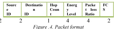
3.3 Proposed packet format
Sourc e ID Destinatio n ID Hop Coun t Energ y Level Packe t loss Ratio
FC S
[image:5.595.307.501.224.274.2]2 2 1 4 4 2
Figure .4. Packet format
In Fig. 4, the proposed packet format is shown. Here the source and destination node ID carries 2 bytes. The third field hop count determines the number of n does connected to the particular node in the cluster. It occupies 1 byte. The energy level occupies which induces the whether the retransmission of packets are occurred with high energy consumption from the source node to the destination node. Packet loss ratio status is verified during the information sharing phase. It occupies 4 bytes. The last filed FCS i.e. Frame Check Sequence which is for error correction and detection in the packet while transmission.
Algorithm:
4
5
PERFORMANCE ANALYSISThe proposed cross layer design is integrated with the Dynamic Source Routing (DSR) protocol. The Network Simulator (NS 2.34) is used to simulate our proposed algorithm. In our simulation, 300 mobile nodes move in a 1500 meter x 1500 meter square region for 120 seconds simulation time. All the nodes have the same transmission range of 250 meters. The simulated traffic used is Constant Bit Rate (CBR) and Poisson traffic. Our
Step 1:
Determine energy spent on both transmission and reception.
Step 2:
Compute the energy cost that includes losses in the transmission.
Step 3:
Calculate the energy spent for data packet and acknowledgement packet transmission.
Step 4:
Determine the total energy for transmitting a packet.
Step 5:
simulation settings and parameters of EECCS are summarized in Table 1
.Table1. Simulation Settings And Parameters
No. of Nodes 300
Area Size 1500 X 1500
Radio Range 250 m
Simulation Time 120 sec
Traffic Source CBR and Poisson
Packet Size 512 bytes
Mobility Model Random Way Point
Protocol DSR
Pause time 5 msec
Packet Queuing Drop Tail 5.1 Performance Metrics
We assess the performance mainly according to the following metrics.
Control overhead: This is defined as the total number of routing control packets normalized by the total number of received data packets.
End-to-end delay: The end-to-end-delay is average over all surviving of data packets from the sources to the destinations.
Packet Delivery Ratio: It is the ratio of the number .of packets received successfully and the total number of packets transmitted.
Packet Loss Ratio: The ratio of occurrence of packet lost to the total number of packets used in the network during one transmission phase is defined as packet loss rate.
Energy consumption level: It keeps the energy level of node which is spent for sending and receiving a data to the total energy spent on the network.
[image:6.595.275.509.69.263.2]Network Lifetime: It shows the lifetime of the nodes for the energy spent on route maintenance phase. The simulation results are presented in the following analysis. We compare our EECCS with the ECAS [10] and CLSMRSCA [11] in presence of congestion environment.
[image:6.595.92.287.170.302.2]Figure.5. Topology and Traffic creation
Fig. 5 shows that traffic creation with the nodes. To identify the packet loss, the constant bit rate traffic is implemented. The delay is produced in packet from source node to destination node via neighbour nodes. Source may choose the different paths to achieve the high packet delivery fraction.
[image:6.595.312.498.423.729.2]Fig.6 shows the results of packet delivery ratio for varying the nodes 10, 20,…300. From the results, we can see that EECCS scheme has higher delivery ratio than the CLSMRSCA and ECAS schemes.
Figure.6. No.of Nodes Vs delivery ratio
Figure.8. No. of Nodes Vs Energy Consumption
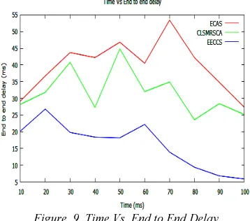
Figure. 9. Time Vs End to End Delay
Fig.7, presents the comparison of energy consumption and mobility. It is clearly shown that the EECCS has low energy consumption than the ECAS and CLSMRSCA.
Fig.8, presents the comparison of energy consumption and Number of Nodes. Nodes are varied as 5, 10, …. 50. It is clearly shown that the EECCS has low energy consumption than the ECAS and CLSMRSCA.
Fig.9, presents the comparison of End to end delay while varying the time from 10 to 100. It is clearly shown that the delay of EECCS has low than the ECAS and CLSMRSCA protocol.
Figure.10.Speed Vs Network lifetime
Fig.10, shows the results of Speed Vs Network Lifetime. From the results, we can see that EECCS scheme has higher Network Lifetime than the CLSMRCSA and ECAS while varying the speed from 20 to 200.
[image:7.595.99.278.294.452.2]Analysis of the proposed scheme is shown in Table 2.
Table 2. Analysis of Proposed Method (EECCS) and Existing Methods (ECAS and CLSMRSCA) in terms of
different parameters
Metrics EECCS CLSMRSCA ECAS
Packet loss ratio (%)
12-57 22-62 29-94
Packet Delivery Ratio (pkts)
48-96 23-78 7-19
Network lifetime (msec)
20-93 18-41 12-34
End to end delay (msec)
20.2-5.9 28.2-25.2 29.2-27.4 Energy
Consumption (Joules) Vs
No. of Nodes 67.2-39.4
82.2-51.2 97.2-89.9
Energy Consumption (Joules) Vs Mobility
14.2-6.9 16.9-78.2 17.2-48.4
6
CONCLUSION [image:7.595.301.509.435.698.2] [image:7.595.300.508.438.694.2]unlimited retransmission of packets happens. So the energy consumption of network goes very high. In this paper, we have developed an Efficient Energy based Congestion Control Scheme for minimum energy consumption which attains the more energy efficiency and reduced congestion among nodes. In the first phase of the scheme, multipath routing is proposed to achieve high network lifetime and throughput. In second phase, Cross Layer design is achieved. Here the information is sent to the source node depends upon the fading of channel determined from destination node. In third phase, the Energy Consumption model is proposed to achieve minimum energy consumption of nodes, acknowledgement and data packets. By using the extensive simulation results, the proposed scheme EECCS achieves the better packet delivery ratio, high network lifetime, low delay and overhead, minimum energy consumption than the existing schemes like CLSMRSCA and ECAS while varying the mobility, time, speed, throughput and number of nodes.
REFRENCES:
[1] Imran Chowdhury, Asaduzzaman, Saki Kowsar, “An Energy Efficient and Cooperative Congestion Control Protocol in MANET”, International Journal of Computer Applications (0975 – 8887) Volume 58– No.17, November 2012, pp.27-34.
[2] K. Srinivas, A. A. Chari, “ ECDC: Energy Efficient Cross Layered Congestion Detection and Control Routing Protocol”, International Journal of Soft Computing and Engineering (IJSCE) ISSN: 2231-2307, Volume-2, Issue-2, May 2012, pp.316-322.
[3] V. V. Appaji, Dr. Sreedhar, “CPCRT: Cross layered and Power Conserved Routing Topology for congestion Control in mobile ad hoc networks”, IOSR Journal of Computer Engineering (IOSRJCE), Volume 3, Issue 5 (July-Aug. 2012), pp. 17-25.
[4] T.Suryaprakash Reddy, Dr. P. Chenna Reddy, “ EOCC: Energy-Efficient Ordered congestion control using cross layer support in Mobile Ad Hoc Network routing”, International Journal of Scientific & Engineering Research, Volume 3, Issue 10, October-2012, pp.1-9.
[5] Vishnu Kumar Sharma and Dr. Sarita Singh Bhadauria, “Congestion and Power Control Technique Based on Mobile Agent and Effect of Varying Rates in MANET”, International
Journal of Advancements in Computer Science and Information Technology [ 2250 – 2440] Vol. 01, No. 1, 2011, pp.24-34.
[6] M. Rajesh Babu, S. Selvan, “An Energy Efficient Secure Authenticated Routing Protocol for Mobile Adhoc Networks”, American Journal of Scientific Research, ISSN 1450-223X Issue 9(2010), pp.12-22. [7] Mohammad Amin Kheirandish Fard , Sasan
Karamizadeh1, Mohammad Aflaki,
“Enhancing Congestion Control to Address Link Failure Loss over Mobile Ad-Hoc Network” International Journal of Computer Networks & Communications (IJCNC) Vol.3, No.5, Sep 2011,pp.177-192.
[8] V. Thilagavathe and Dr. K. Duraiswamy, “Cross Layer based Congestion Control Technique for Reliable and Energy Aware Routing in MANET”, International Journal of Computer Applications (0975 – 8887), Volume 36– No.12, December 2011, pp.1-6. [9] S.Karunakaran & P.Thangaraj, “A Cluster
Based Congestion Control Protocol For Mobile Ad hoc Networks”, International Journal of Information Technology and Knowledge Management, July-December 2010, Volume 2, No. 2, pp. 471-474.
[10] S.Sheeja and Ramachandra.V.Pujeri, “Effective Congestion Avoidance Scheme for Mobile Ad Hoc Networks”, International Journal of Computer Network and Information Security, January 2013, Vol.1, pp.33-40. [11] S.Sheeja and Ramachandra.V.Pujeri, “Cross
Layer Based Secure Multipath Routing Scheme for Congestion Avoidance in MANET”, European Journal of Scientific Research, Vol. 97, No. 3, 2013, pp.331-344. [12] Choong Seon Hong, Sungwon Lee,
“Cross-Layer Optimization for Congestion and Power Control in OFDM-Based Multi-Hop Cognitive Radio Networks ”, IEEE Transactions on
Communications, Vol.60, Issue 8, 2012, pp.2101-2112.