CPIM-86™
Programmer's Guide
Copyright ~ 1981 Digital Research
P.O. Box 579 801 Lighthouse Avenue Pacific Grove, CA 93950
(408) 649-3896 TWX 910 360 5001
COPYRIGHT
Copyright
©
1981 by Digital Research. All rights reserved. No part of this publication may be reproduced, transmitted, transcribed, stored in a retrieval system, or translated into any language or computer language, in any form or by any means, electronic, mechanical, magnetic, optical, chemical, manual or otherwise, without the prior written permission of Digital Research, Post Office Box 579, Pacific Grove, California, 93950.This manual is, however, tutorial in nature. Thus, the reader is granted permission to include the example programs, either in whole or in part, i.nhis own programs.
DISCLAIMER
Digital Research makes no re'J.')resentations or warranties with respect to the contents hereof and specifically disclaims any imt;'lied warranties of merchan tabi 1 i ty or f i tnes s for any particular purl?ose. Further, Diqi tal Research reserves the right to revise this publication and to make chanqep f rom time to t tme in the content hereof without obligation of Digital Research to notify any person of such revision or changes.
TRADEMARKS
CP/M is a registered trademark of Digital ~esearch.
CP/M-86, ASM-86, DDT-86 and TEX-80 are trademarks of Digital Research.
Foreword
This manual assists the 8086 assembly languaqe proqrammer
k . . / 8 6 rr'f'.1 . t I - . f ; 1 .
wor lng 1.n a CP M- enVlronmen. t assumes you are ._am.~ __ lar with the CP /~-1-86 impJ.ementat ion of CP/M. and have read the following Digital Research publications:
• CP/M 2 Documentation
• CP/M-86 System Guide
The reader should also be familiar with the 8086 assembly language instruction set, which i.s defi.ned in Intel .... s 8086 Family User .... s Manual.
The first section of this manual discusses ASM-86 operation and the var io~ assembl er options which may be enabled 'vhen invoking ASM-86. One of thes-e options contro'ls the hexadecimal out?ut format. ASM-86 can generate 8086 machine code in either Intel or Digital Research format. These two hexadecima1 formats are described in Appendix A.
The second section discusses the elements of AS~-86 assemblv language. It defines ASM-86 .... s character set, constants, vari.ables, identifiers, operators, expressions, and statements.
The third section discusses the ASM-86 directives, which per form housekeeping functions such as requesting condi t i.onal assembly, including multiple source fi.les, and contro] 1.inq the format of the listing pri.ntout.
The fourth section is a concise summary of the 8086
instruction mnemonics accepted by ASM-86. The mnemonics used bV the Digital Research assembler are the same as those used by the Intel assembler except for four instructions: the intra-segment short jump, and inter-seqment jump, return and call instructions. These differences are summarized in Appendix B.
The fifth section of this manual discusses the code-macro facilities of ASM.-86. Code-macro definition, specifiers and modifiers as well as nine special code-macro directives are discussed. This information is also summarized in Appendix H.
Table of Contents
1 Introduction
1.1 Assembler O?eration
1.2 Optional Run-time Parameters
1.3 Abortinq ASM-86
2 Elements of ASM-86 Assembly Language
2.1 ASM-86 Character Set •
2.2 Tokens and Separators
2.3 Delimiters.
·
. .
.
. .
.
.
2.4 Constants2.4.1 2.4.2
Numeric Constants • Character Strings •
.
.
. .
.
.
2.5 Identifiers
· . . . . .
. .
.
. .
.
. .
. .
.
.
2.5.12.5.2
Keywords • • • • • • • • Symbols and Their Attributes
2.6 Operators
· .
.
.
. . . .
.
. . . . . . .
.
2.6.1 Operator Examples • 2.6.2 Operator Precedence.
2.7 Expressions
2.9 Statements • •
3 Assembler Directives
3.1 Introduction
. . ·
· .
.
· ·
3.2 Segment Start Directives·
·
3.2.1 The CSEG Directive·
3.2.2 The DSEG Directive·
3.2.3 The SSEG Directive 3.2.4 The ESEG Directive·
3.3 The ORG Directive
· . .
·
·
Table of Contents
(continued)
3.4 The IF and ENDIF Directives
.
. . .
. .
. .
.
.
3.5 The. INCLUDE Directive3.6 The END Directive
3.7 The EOU nirective
3.8 The DB Directive
.
3.9 The DW Directive
.
.
..
...
3.10 The DD Directive
.
.
.
.
.
. . .
3.11 The RS Directive3.12 The RB Directive
.
.
.
.
.
.
.
. .
.
. . .
3.13 The RW Directive3.14 The TITLE Directive •
3.15 The PAGESIZE Directive
3.16 The PAGEWIDTH Directive •
3.17 The EJECT Directive •
3.18 The SIMFORM Directive
3.19 The NOLIST and LIST Directives
4 The ASM-86 Instruction Set
4.1 Introduction • • • . •
.
.
.
.
. .
. . . . . . .
4.2 Data Transfer Instructions •4.3 Arithmetic, Logical, and Shift Instructions
4.4 String Instructions
4.5 Control Transfer Instructions
4.6 Processor Control Instructions.
24
24
24
25
25
26
26
27
27
27
27
27
28
28
28
28
29
31
33
38
39
Table of Contents
(continued)
5 Code-Macro Facilities
6
5.1 Introduction to Code-macros
·
.
.
. . .
5.2 Specifiers
5.3 Modifiers
·
.
.
.
. . .
5.4 Range Specifiers.
·
.
.
.
..
... .
S.5 Code-macro Directives
5.5.1 5.5.2 5.5.3 5.5.4 5.5.5 5.5.6 DDT-86
6.1 DDT-86
6.1.1 6.1.2 6.1.3 6.1.4 6.1.5
6.2 DDT-86
6.2.1 6.2.2 6.2.3 6.2.4 6.2.5 6.2.6 6.2.7 6.2.8 6.2.9 6.2.10 6.2.11 6.2.12 6.2.13 6.2.14 6.2.15 6.2.16
SEGFIX • • • • NOSEGFIX
MODRM • • • • • RELB and RELW • DB,
nw
and DD • DBI'r • • • • •Operation
.
.
.
Invoking DDT-86·
·
· ·
·
·
·
·
·
·
·
·
DDT-86 Command Conventions Sl?ecifying a 20-Bit Address Terminating DDT-86
· · ·
·
·
·
·
·
·
·
·
·
· ·
DDT-86 Operation with Interrupts
Commands
.
.
.
· ·
·
The A (Assemble) Command
The D (Display) Command
·
·
·
The E (Load for Execution) Command The F (Fill) Command·
·
·
·
·
·
The G (Go) Command·
· · · ·
·
·
The H (Hexadecimal Math) Command The I (Input Command Tail) CommandThe L (List) Command
· · ·
·
The M (Move) Command
·
·
· ·
The R (Read) Command
·
·
The S (Set) Command
·
·
·
·
The T (Trace) Command·
· · ·
·
The U (Untrace) Command· ·
·
·
The V (Value) Command·
·
·
The W (Wr i te) Command
·
The X (Examine CPU State) Command
6.3
Table of Contents
(continued)
Default Segment Values •
6.4 Assembly Language Syntax for A and L Commands
6.5 DDT-86 Sample Program
.
. .
. . .
.
. .
66
69
Appendixes
A ASM-86 Invocation • • • •
B Mnemonic Differences from the Intel Assembler •
C ASM-86 Hexadecimal Output Format
D Reserved Words
E ASM-86 Instruction Summary
F Sample Program
.
.
.
·
.
.
G Code-macro Definition SyntaxB ASM-86 Error Messages
·
I DDT-86 Error l-1essages
·
79
81
83
87
89
93
99
101
Section 1
Introduction
1.1 Assembler Operation
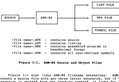
ASM-S6 processes an 8086 assembly language source file in three passes and produces three output files, including an 8086 machine language file in hexadecimal format. This object file may be in either Intel or Digital Research hex format, which are described in Appendix C. ASM-86 is shipped in two forms: an 8086 cross-assembler designed to run under CP/M on an Intel 8080 or Zilog Z-80 based system, and a S086 assembler designed to run under CP/M-86 on an Intel 8086 or S088 based system. ASM-86 typically produces three output files from one input file as shown in Figure 1-1, below.
SOURCE
<file name>.A86 <file name>.LST <file name>.H86
<file name>.SYM
Figure 1-1.
ASM-86
contains source contains listing
--'"
LIST FILE
HEX FILE
SYMBOL FILE
contains assembled program in hexadecimal format
contains all user-defined symbols
ASM-86 Source and Object Files
Figure 1-1 also lists ASM-86 filename e.xtensions. ASM-86 accepts a source file with anv three letter extension, but if the exte'nsion is omitted from the invoking command, it looks for the specified filename with the extension .A86 in the directorv. If no filename is specified and the file has an extension other than .A86 or has no extension at all, ASM-86 returns an error message.
[image:12.626.87.543.305.620.2]CP/M-86 Proqrammer~s Guide 1.1 Assembler O?eration
Invoke ASM-86 by entering a command of the following form:
ASM86 <source filename> [ $ <optional parameters>
Section 1.2 explains the optional parameters. Specify the source file in the following form:
where
[<optional drive>:]<filename>[.<optional extension>]
<optional drive> is a valid drive letter specifying the source file~s location. Not needed if source is on current drive.
<filename> is a valid CP/M filename of 1 to 8 characters.
<optional extension> is a valid file extension of 1 to 3 characters, usuall.y .A86.
Some examples of valid ASM-86 commands are:
A>ASM86 B:BIOS88
A>ASM86 BIOS88.ASM $FI AA HB PB SB
A>ASM86 D:TEST
Once invoked, ASM-86 responds with the message:
CP/M 8086 ASSEMBLER VER x.x
where x.x is the ASM-86 version number. ASM-86 then attempts to open the source file. If the file does not exist on the designated drive, or does not have the correct extension as described above, the assembler displays the message:
NO FILE
If an invalid parameter is given in the optional parameter list, ASM-86 displays the message:
PARAMETER ERROR
After opening the source, the assembler creates the output files. Usually these are placed on the current disk drive, but they
may be redirected by optional parameters, or by a drive
CP/M-86 Programmer's Guide 1.1 Assembler Operation
During assembly, ASM-86 aborts if an error condition such as disk full or symbol table overflow is detected. When ASM-86 detects an error in the source file, i t places an error message line in the listing file in front of the line containing the error. Each error message has a number and gives a brief explanation of the error. Append ix H lists A.SM-86 error messages. When the assembly is complete, ASM-86 displays the message:
END OF ASSEM.BLY. NUMBER OF ERRORS: n
1.2 Optional Run-time Parameters
rrhe dollar-sign character, $, flaqs an optional string of run-time parameters. A parameter is a single letter followed by a single letter device name specification. The parameters are shown in Table 1-1, below.
Table 1-1. Run-time Parameter Summary
Parameter
I
~o
SpecifyA
H
P S
F
source file nevice hex output file device list file device
symbol file device
format of hex output file
I
validA, B, A
A
.
. .
A
. .
.
I, DArguments
C,
...
PP, X, Y, Z P, X, Y, Z P, X, V, Z
All parameters are optional, and can be entered in the command line in any order. Enter the dollar sign only once at the beginning of the parameter string. Spaces may separate parameters, but are not required. No space is permitted, however, between a parameter and its device name.
A device name must follow parameters A, H, P and S. The devices are labeled:
A, B, C, ••• P or X, Y, Z
Device names A through P respective1y specify disk drives A through P. X specifies the user console (CON:), Y specifies the line printer (LST:), and Z suppresses output (NUL:).
CP/M-86 Programmer~s Guide 1.2 Optional Run-time Parameters
The F parameter requires either an I or a D argument. When I is specified, ASM-86 produces an object file in Intel hex format. A D argument requests Digital Research hex format. Appendix C discusses these formats in detail. If the F parameter is not entered in the command line, ASM-86 produces Digital Research hex format.
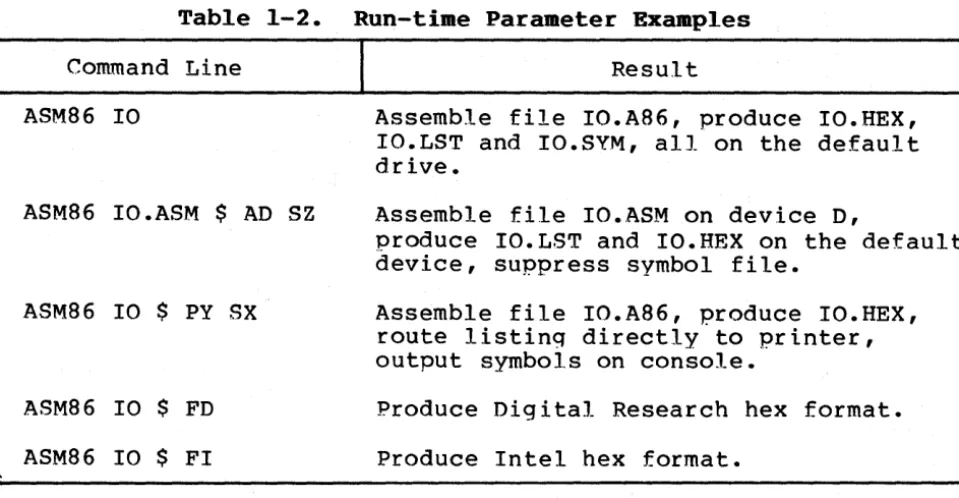
Table 1-2. Run-time Parameter Examples
Command Line
I
ASM86 10
ASM86 IO.ASM $ AD SZ
ASM86 10 $ PY SX
ASM86 10 $ FD
ASM86 10 $ FI
1.3 Aborting ASM-86
Result
Assemble file IO.A86, produce IO.HEX, IO.LST and IO.SYM, all on the default drive.
Assemble file IO.ASM on device D,
produce IO.LST and IO.HEX on the default device, suppress symbol file.
Assemble file IO.A86, produce IO.HEX, route listing directly to printer, output symbols on console.
Produce Digital Research hex format.
Produce Intel hex format.
You may 'abort ASM-86 execution at any time by hitting any key on the console keyboard. When a key is pressed, ASM-86 responds with the question:
USER BREAK. OK (YIN) ?
[image:15.623.70.550.162.411.2]Section 2
Elements of ASM-86 Assembly Language
2.1 ASM-86 Character Set
ASM-86 recognizes a subset of the ASCII character set. The valid characters are the alphanumer ics, special characters, and non-printing characters shown below:
A B C D E F G H I lJ K L M N 0 P Q R S T U VW X y Z
a b c d e f q h i j k 1 m n o P q r s t u v
,.,
x y z0 1 2 3 4 5 6 7 8 9
+
*
/ = ) ~!
.
@ $-
.
,
.
space, tab, carriage-return, and line-feed
Lower-case letters are treated as upper-case except wi thin strings. Only alphanumerics, special characters, and spaces may appear within a string.
2.2 Tokens and Separators
A token is the smallest meaningful unit of an ASM-86 source program, much as a word is the smallest meaningful unit of an English composition. Adjacent tokens are commonly separated by a blank character or s"9ace. Any sequence of spaces may appear wherever a single space is allowed. ASM-86 recognizes horizontal tabs as separators and interprets them as spaces. Tabs are eXl?anded to spaces in the list fi Ie. The tab stops are at each eighth column.
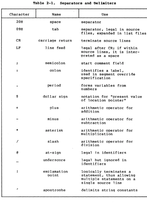
2.3 Delimiters
Delimiters mark the end of a token and add special meaning to the instruction, as opposed to separators, whLch merely mark the end of a token. When a delimiter is present, separators need not be used. However, sepa.rators after delimiters can make your program easier to read.
CP/M-86 Programmer~s Guide 2.3 Delimiters
Table 2-1. Separators and Delimiters
Character 20H 09H CR LF ; $ +
*
I @ Name space tabcarriage return
line feed
semicolon
colon
period
dollar sign
plus minus asterisk slash at-sign underscore exclamation point apostrophe Use separator
separator, legal in source files, expanded in list files
terminate source lines
legal after CR; if within source lines, it is inter-preted as a space
start comment field
identifies a label,
used in segment override specification
forms variables from numbers
notation for "present value of location pointer"
arithmetic operator for addition
arithmetic operator for subtraction
arithmetic operator for multiplication
arithmetic operator for
division
.-legal jn identifiers
legal but ignored in identifiers
logically terminates a statement, thus allowing multiple statements on a single source line
[image:17.624.59.542.49.724.2]CP/M-86 Programmer~s Guide 2.4 constants
2.4 Constants
A constant is a value known at assembly time that does not change while the assembled program is executed. A constant may be either an integer or a character string.
2.4.1 Numeric Constants
A numeric constant is a 16-bit value in one of several bases. The base, called the radix of the constant, is denoted by a trailing radix indicator. The radix indicators are shown in Table 2-2, below.
Table 2-2. Radix Indicators for Constants
Indicator
I
Constant TypeI
BaseB binary 2
0 octal 8
Q octal 8
n
decimal 10H hexadecimal 16
ASM-86 assumes that any numeric constant not terminated with a
radix indicator is a decimal constant. Radix ind.icators may be upper or lower case.
A constant is thus a sequence of dig its followed by an opt ional radix indicator, where the digits are in the range for the radix. Binary constants must be composed of O~s and l~s.· Octal digits range from a to 7: decimal digits range from a to 9. Hexadecimal constants contain decimal digits as well as the hexadecimal digits A
(laD), B (lID), C (12D), D (13D), E (14D), and F (15D). Note that the leading character of a hexadecimal constant must be either a leading a or a decimal diqit so that ASM-86 cannot confuse a hex constant with an identifier. The following are valid numeric constants:
1234 1234H 33770
1234D OFFEH OFE3H
l100B 33770 1234d
1111000011110000B 13772Q
CP/M-86 Programmer~s Guide 2.4 Constants
2.4.2 Character Strings
ASM-86 treats an ASCII character string delimited by
apostrophes as a string constant. All instructions accept only one-or two-character string constants as valid arguments. Instructions treat a one-character string as an 8-bit number. A two-character string is treated as a l6-bit number with the value of the second character in the low-order byte, and the value of the first character in the high-order byte.
The numeric value of a character is its ASCII code. ASM-86 does not translate case within character strings, so both upper- and lower-case letters can be used. Note that only alphanumer ics, special characters, and spaces are allowed within strinqs~
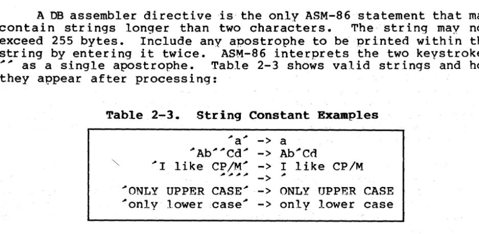
A DB assembler directive is' the only ASM-86 statement that may contain strings longer than two characters. The string may not exceed 255 bytes. Include any apostrophe to be printed within the string by entering it twice. ASM-86 interprets the two keystrokes
~~ as a single apostrophe. Table 2-3 shows valid strings and how they appear after processing:
Table 2-3. String Constant Exaaples
~a~ -> a
~Ab~~Cd~ -> Ab~Cd
~ ~I like CP/M~ -> I like CP/M
~~~~
-> ~
~ONIJY UPPER CASE~ -> ONLY UPPER CASE
~only lower case ~
-> only lower case
2.5 Identifiers
Identifiers are character sequences which have a special, symbolic meaninq to the assembler. All identifiers in ASM-86 must obey the following rules:
1. The fir s t c h a r act e r m us t be alp h a be tic (A, ••• Z , a, ••• z).
2. Any subsequent characters can be either alphabetical or a numeral (0,1, ••••• 9). ASM-A6 ignores the special characters @ and , but they are still leqal. For example, a_b becomes abe
[image:19.626.69.538.231.460.2]CP/M-86 Programmer~s Guide 2.5 Identifiers
Identifiers are of two types. The first are keywords, which have predefined meanings to the assembler. The second are symbols, which are defined by the user. The followinq are all valid
identifiers:
NOIJIST WORD AH
Third street
How are you today
varIable@number@l234567A90
2.5.1 Keywords
A keyword is an identifier that has a predefined meaning to the assembler. Keywords are reserved; the user cannot define an identifier identical to a keyword. For a com?,lete list of keywords, see Appendix D.
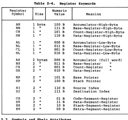
ASM-86 recogni zes five types of keywords: instructions, directives, operators, registers and predefined numbers. 8086 instruction mnemonic keywords and the actions they ini tiate are defined in Section 4. Directives are discussed in Section 3. Section 2.6 defines operators. Table 2-4 lists the ASM-86 keywords that identify 8086 registers.
CP/M-86 Programmer~s Guide 2.5 Identifiers
Table 2-4. Register Keywords
Register Numeric
Symbol Size Value Meaning
AH 1 byte 100 B Accumulator-High-Byte
BH 1 II I I I
B Base-Register-High-Byte
CH 1 II
101 B Count-Register-High-Byte
DH 1 II 110 B
nata-Register-High-Byte
AL 1 II 000 B
Accumulator-Low-Byte
BL 1 II
011 B Base-Register-Low-Byte
~L 1
"
001 Bcount-Reqister-~OW-BYte
DL 1"
010 B Data-Register-L w-ByteAX 2 bytes 000 B ,Accumu1a tor (full word)
BX 2
"
011 B Base-'Register IIex
2"
001 B Count-Register"
DX 2"
010 'B Data-Register IIBP 2 II
101 B Base Pointer
SP 2
"
100 -B Stack Pointer;SI 2
"
110 B Source IndexDI 2
"
I I I B Destination IndexCS 2 II
01 B Code-Segment-Register
DS 2
"
11 B Data-Segment-RegisterSS 2
"
10 B Stack~Segment-RegisterES 2 II 00 B
Extra-Segment-Register
2.5.2 Symbols and Their Attributes
A symbol is a user-def.ined identifier that has attributes which specify what kind of information the symbol represents. Symbols fall into three categories:
• variables • labels • numbers
[image:21.627.80.525.50.468.2]CP/M-86 Programmer~s Guide 2.5 Identifiers
• Segment - tells which seqment was beinq assembled when the variable was defined.
• Offset - tells how many bytes there are between the
beginning of the segment and the location of this variable.
• Type - tells how many bytes of data are manipulated when this variable is referenced.
A Segment may be a code-segment, a data-segment, a stack-segment or an extra-stack-segment depending on its contents and the register that contains its starting address (see Section 3.2). A segment may start at any address divisible by 16. ~SM-86 uses this boundary value as the Segment portion of the variable~s definition.
The Offset of a variable may be any number between 0 and OFFFFH or 65535D. A variable must have one of the following Type attributes:
• BYTE • WORD • DWORD
BYTE specifies a one-byte variable, WORD a two-byte variable and DWORD a four-byte variable. The DB, DW, and DO directives respectively define variables as these three types (see Section 3). For example, a variable is defined when it appears as the name for a storage directive:
VARIABLE DB 0
A variable may also be defined as the name for an EQU directive referencing another label, as shown below:
VARIABLE EQU ANOTHER VARIABLE
Labels identify locations in memory that contain instruction statements. They are referenced with jumps or calls. All labels have two attributes:
• Segment • Offset
Label segment and offset attributes are essentially the same as variable segment and offset attributes. Generally, a label is defined when it precedes an instruction. A colon, :, separates the label from instruction; for example:
LABEL: ADD AX,BX
A label may also appear as the name for an EQU directive referencing another label; for example:
CP/M-86·Programmer""s Guide 2.5 Identifiers
Numbers may also be defined as symbols. A number symbol is treated as if you had explicitly coded the number it represents. For· example:
Number five EQU 5
MOV AL,Number_five
is equivalent to:
MOV AL,5
Section 2.6 describes operators and their effects on numbers and number symbols.
2.6 Operators
AS M - 8 6 0 per a tor s fall into the follow i n 9 cat ego r i e s : arithmetic, logical, and relational operators, segment override, variable manipulators and creators. Table 2-5 defines ASM-86 operators. In this table, a and b represent two elements of the expression. The validity column defines the type of operands the operator can manipulate, using the or bar character, " to separate alternatives.
Table 2-5. ASM-86 Operators
Syntax Result Validity
Logical Operators
.',
a XOR b bit-by-bit logical EXCLUSIVE a, b
=
n~er
OR of a and b.a OR b bit-by-bit loqical OR of a a, b
=
numberand b.
a AND b bit-by-bit logical .AND of a a, b
=
number and b. [image:23.623.56.558.58.755.2]CP/M-86 Programmer~s Guide 2.6 Operators
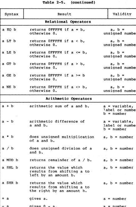
Table 2-5. (continued)
Syntax Result Validity
Relational Operators
a
EO
b returns OFFFFH if a = b,· a,b =otherwise O. unsigned number
a LT b returns OFFFFH if a < b, a, b =
otherwise O. unsigned number
a LE b returns OFFFFH if a <= b, a, b =
otherwise O. unsigned number
a GT b returns OFFFFH if a > b, a, b =
otherwise O. unsigned number
a GE b returns OFFFFH if a >= b a, b =
otherwise O. unsigned number
a NE b returns OFFFFH if a <> b, a, b =
otherwise O. unsigned number
Arithmetic Operators
a + b arithmetic sum of a and b. a = variable, 1.abel or number b = number
a
-
b arithmetic difference of a = variable,a and b. label or number
b = number
a
*
b does unsigned multiplication a, b = number of a and b.a / b does unsigned division of a a, b = number and b.
a MOD b returns remainder of a / b. a, b = number
a SHL b returns the value which
a,
b = numberresults from shifting a to left by an amount b.
a SHR b returns the value which a, b = number
results from shifting a to the right by an amount b.
+ a gives a. a = number
[image:24.626.88.525.59.723.2]CP/M-86 Programmer~s Guide
Syntax
<seg reg>: <addr exp>
SEG a
OFFSET a
TYPE a
LENGTH a
LAST a
a PTR b
.a
$
Table 2-5. (continued)
Result
Segment OVerride
overrides assembler~s choice of segment register.
Variable Manipulators, Creators
creates a number whose value is the segment value of the variable or label a.
creates a number whose value is the offset value of the variable or label a.
creates a number. If the variable a is of type BYTE, WORD or DWORD, the value of the number will be 1, 2 or 4, respectively.
creates a number whose value is the LENGTH attribute of the variable a. The length attribute is the number of bytes associated with the variable.
if LENGTH a > 0, then LAST a
=
LENGTH a - I; if LENGTH a=
0, then LAST a=
O.creates virtual variable or label with type of a and attributes- of b
creates variable with an offset attribute of a.
Segment attribute is current segment.
creates label with offset equal to current value of location counter: segment attribute is current
segment.
2.6 Operators
Validity
<seg reg>
=
CS, DS, SS or ESa
=
labelI
variablea
=
labelI
variablea
=
labelI
variablea
=
labelI
variablea
=
labelI
variablea
=
BYTEI
WORD,
I
DWORDb
=
<addr exp>a
=
number [image:25.626.69.532.48.731.2]CP/M-86 Programmer's Guide 2.6 Operators
2.6.1 Operator Examples
Log ica 1 operators accept only numbers as operands. perform the boolean logic operations AND, OR, XOR, and NOT. example:
OOFC 0080 0000 B180 0002 B003
MASK EQU
SIGNBIT EQU MOV MOV
OFCH 80H
CL,MASK AND SIGNBIT AL,NOT MASK
"rhey For
Relational operators treat all operands as unsigned numbers. The relational operators are EQ (equal), LT (less than), LE (less than or equal), GT (greater than), GE (greater than or equal), and NE (not equal). Each o~erator compares two operands and returns all ones (OFFFFH) if the specified relation is true and all zeros if it
is not. For example:··
OOOA 0019
0004 B8FFFF 0007 B80000
LIt.~ITl EQU LIMIT2 EQU
MOV MOV
10 25
AX,LIMITI LT LIMlrr2 AX,LIMITI GT LIMIT2
Addition and subtraction operators compute the arithmetic sum and difference of two operands. The first operand may be a variable, label, or number, but the second operand must be a number. When a number is added to a variable or label, the result is a variable or label whose offset is the numeric value of the second operand plus the offset of the first operand. Subtraction from a variable or label returns a variable or label whose offset is that of first operand decremented by the number specified in the second operand. For example:
0002 0005 OOOA FF
OOOB 2EAOOBOO OOOF 2E8AOEOFOO 0014 B303
COUNT DISPI FLAG EQU EQU DB .MOV MOV MOV 2 5 OFFH AL,FLAG+l CL,FLAG+DISPI BL,DISPI-COUNT
The multiplication and division operators
*,
I,
MOD, SHL, and SHRaccept only numbers as operands.*
and / treat all operators as unsigned numbers. For example:0016 BES500 0019 B310
0050
OOlB B8AOOO
MOV MOV BUFFERSIZE MOV SI,256/3 BL,64/4
EQU 80
CP/M-86 Programmer"'"s Guide 2.6 Operators
Unary operators accept both signed and unsigned operators as shown below:
OOIE Bl23 0020 'B007 0022 B2F4
MOV 1'10V MOV CL,+35 AL,2--5 DL,-12
When manipulating variables, the assembler decides which segment register to use. You may override the assembler"'"s choice by
sp~cifying a different register with the segment override operator. The syntax for the override operator is <segment register> <address expression> where the <segment register> is CS, DS,
ss,
or ES. For example:0024 368B4720 0028 268BOE5BOO
. MOV MOV
AX,SS:WORDBUFFER[BXl CX,ES:ARRAY
A variable manipulator creates a number equal to one attri.bute of its variable operand. SEG extracts the variable"'"s segment value, OFFSET its offset value, TYPE its type value (1, 2, or 4), and LENGTH the number of bytes associated with the variable. LAST compares the var iable~ s LENGTH wi th 0 and if greater, then decrements LENGTH by one. If LENGTH equals 0, LAST leaves it
unchanged. Variable manipulators accept only vari.ables as operators. For example:
002D 000000000000 WORDBUFFER 0033 0102030405 BUFFER
0038 B80500 003B B80400 003E B80l00 0041 B80200
MOV MOV MOV MOV OW DB 0,0,0 1,2,3,4,5
AX,LENGTH BUFFER AX,LAST BUFFER AX,TY1?E BUFFER AX,TYPE WORDBUFFER
The PTR operator creates a virtual variable or label, one valid only during the execution of the instruction. It makes no chanqes to either of its operands. The temporary symbol has the same Type attribute as the left operator, and all other attributes of the right operator as shown below.
0044 C60705 0047 8A07 0049 FF04
MOV MOV INC
BYTE PTR [BX], 5 AL,BYTE PTR [BX] WORD PTR [SI]
The Period operator, ., creates a variable in the current data segment. The new var i,able has a segment attr ibute equal to the current data segment and an offset attribute equal to its operand. Its operand must be a number. For example:
004B AlOOOO 004E 268BlE0040
MOV MOV
AX, .0
CP/M-86 Programmer's Guide 2.6 Operators
The Dollar-sign operator, $, creates a label- with an offset attribute equal to the current value of the location counter. The label's segment value is the same as the current code segment. This operator takes no operand. For example:
2.6.2
0053 E9FDFF 0056 RBFE 0058 E9FD2F
Operator Precedence
JMP JMPS JMP
$
$
$+3000H
Expressions combine variables, labels or numbers with operators. ASM-86 allows several kinds of eX1;>ressions which are discussed in Section 2.7. This section defines the order in which operations are executed should more than one operator appear in an expression.
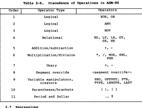
In general, ASM-86 evaluates expressions left to right, but operators with higher precedence are evaluated before operators with lower precedence. When two operators have equal precedence, the left-most is evaluated first. Table 2-6 presents ASM-86 operators in order of increasing precedence.
Parentheses can override normal rules of precedence. The part of an expression enclosed in parentheses is evaluated first. If parentheses are nested, the innermost expressions are evaluated first. Only five levels of nested parentheses are legal. For example:
15/3 + 18/9
=
5 + 2=
7CP/M-86 Programmer~s Guide 2.6 Operators
Table 2-6. Precedence of Operations in ASM-86
Order
I
Operator Type1 Logical
2 Logical
3 Logical
4 Relational
5 Addition/subtraction
6 Multiplication/division
7 Unary
8 Segment override
9 Variable manipulators,
creators
10 Parentheses/brackets
11 Period and Dollar
2.7 Expressions
1
OperatorsXOR, OR
AND
NOT
EO, LT, T..IE, GT,
GE, N'E
+,
-*, /,
MOD, SHL, SHR+,
-<segment override>:
SEG, OFFSET, P~R,
TYPE, LENGTH, LAST
)
,
., $
ASM-86 allows address, numeric, and bracketed expressions. An address expression evaluates to a m.emory address and has three components:
• A segment value • An offset value • A type
Both variables and labels are address expressions. An address expression is not a number, but its components are. Numbers may be combined with operators such as PTR to make an address expression.
A numer ic expression evaluates to a number. It does not contain any variables or labels, only numbers and operands.
[image:29.618.54.551.53.430.2]CP!M-86 Programmer~s Guide 2.7 Expressions
Use the + operator between a base register and an index register to specify both base- and index-register addressing. For example:
MOV variable[bx] ,0
MOV AX, [BX+DI]
MOV AX, [SI]
2.8 Statements
Just as "tokens" in this assembly language correspond to words in English, so are statements analogous to sentences. A statement tells ASM-86 what action to perform. Statements are of two types: instructions and directives. Instructions are translated by the assembler into 8086 machine language instructions. Directives are not translated into machine code but instead direct the assembler to perform certain clerical functions.
Terminate each assembly language statement with a carriage return (CR) and line feed (LF), or with an exclamation point, !, which ASM-86 treats as an end-of-line except in comments. Mul tiT;>le assembly language statements can be written on the same physical line if separated by exclamation points.
The ASM.-86 instruction set is defined in Section 4. The syntax for an instruction statement is:
[label: ] [prefix] mnemonic [ 0p.erand(s)] [icomment]
where the fields are defined as:
label:
prefix
mnemonic
A symbol followed by":" defines a label at the current value of the location counter in the current segment. This field is optional.
Certain machine instructions such as LOCK and REP may prefix other instructions. This field is optional.
CP/M-86 Programmer~s Guide 2.8 Statements
operand(s)
comment
An instruction mnemonic may require other symbols to represent operands to the instruction. Instructions may have zero, one or two operands.
Any semicolon (:) appearing outside a character string begins a comment, which is ended by a carriage return. Comments improve the readability of programs. This field
is optional.
ASM-86 directives are descr ibed in Sect ion 3. The syntax for a directive statement is:
[name] directive operand (s) [:comment]
where the fields are defined as:
name
directive
operand(s)
comment
Unlike the label field of an instruction, the name field of a directive is never terminated with a colon. Directive names are legal for only DB, DW, DD, RS and EQU. For DB, DW, DD and RS the name is optional: for EQU it is required.
One of the directive keywords defined in Section 3.
Analogous to the operands to the instruction mnemonics. Some directives, such as DB, DW, and. DO, allow any operand while others have special requirements.
3.1 Introduction
Section 3
Assembler Directives
Directi.ve statements cause AS~-86 to perform housekeeping functions such as assigning portions of code to logical segments, requesting conditional assembly, defining data items, and specifying listing file format. General syntax for directive statements appears in Section 2.8.
In the sections that follow, the specific syntax for each directive statement is given under the heading and before the explanation. These syntax lines use special symbols to represent possible arguments and other alternatives. Square brackets, [], enclose optional arguments. Angle brackets, <>, enclose descriptions of user-supplied arguments. no not include these
symbols when coding a directive.
3.2 Segment Start Directives
At run-time, every 8086 memory reference must have a l6-bit segment base value and a l6-bi t offset value. These are combined to produce the 20-bit effective address needed by the CPU to physically address the location. The 16-bit segment base value or boundary is contained in one of the segment registers CS, DS,
ss,
or ES. The offset value gives the offset of the memory reference from the segment boundary. A l6-byte physical segment is the smallest relocatable unit of memory.ASM-86 predefines four logical segments: the Code Segment, Data Segment, Stack Segment, and Extra Segment, which are respectively addressed by the CS, OS, SS, and ES registers. Future versions of ASM-86 will support additional segments such as multiple data or code segments. All ASM-86 statements must be assigned to one of the four currently supported seqments so that they can be referenced by the
cpu.
A segment directive statement, CSEG, DSEG, SSEG, or ESEG, specifies that the statements following it belong to a specific segment. The statements are then addressed by the corresponding segment register unless a segment override is included with the instruction. ASM-86 assigns statements to the specified segment until it encounters another segment directive.Instruction statements must be assigned to the Code Segment. Directive statements may be assigned to any segment. ASM-86 uses these assignments to change from one segment register to another. For example, when an instruction accesses a memory variable, ASM-86 must know which segment contains the variable so it can generate a
CP/M-86 Programmer~s Guide
3.2.1 The CSEG Directive
CSEG CSEG CSEG
<numeric expression>
$
3.2 Segment Start Directives
This directive tells the assembler that the followinq statements belong in the Code Segment. All instruction statements must be assigned to the Code Segment. All directive statements are legal within the Code Segment.
Use the first form when the location of the segment is known at assembly time: the code generated is not relocatable. Use the second form when the segment locat ion is not known at assembly time; the code generated is relocatable. Use the third form to continue the Code Segment after it has been interru~ted by a DSEG, SSEG, or ESEG directive. The continuing Code Segment starts with the same attributes, such as location and instruction pointer, as the
previous Code Segment.
-3.2.2 The DSEG Directive
DSEG DSEG DSEG
<numeric expression>
$
This directive specifies that the following statements belong to the Data Segment. The Data Segment primarily contains the data allocation directives DB, DW, DO and RS, but all other directive statements are also legal. Instruction statements are illegal in the Data Segment.
Use the first form when the location of the segment is known at assembly time; the code generated is not relocatable. Use the second form when the segment location is not known at assembly time: the code generated is relocatable. Use the third form to continue the Data Segment after it has been interrupted by a CSEG, SSEG, or ESEG directive. The continuing Data Segment starts with the same attributes as the previous Data Segment.
3.2.3 The SSEG Directive
SSEG SSEG SSEG
<numeric expression>
$
The SSEG directive indicates the beginning of source lines for the Stack Segment. Use the Stack Segment for all stack operations. All directive statements are legal in the Stack Segment, but
CP/M-86 Programmer~s Guide 3.2 Segment Start nirectives
Use the first form when the location of the segment is known at assembly time~ the code generated is not relocatable. Use the second form when the seqment location is not known at assembly time ~
the code generated is ielocatable. Use the third form to c~ntinue the Stack Segment after it has been interrupted by a CSEG, DSE~, or ESEG directive. The continuing Stack Segment starts with the same attributes as the previous Stack Segment.
3.2.4 The ESEG Directive
ESEG ESEG ESEG
<numeric expression>
$
This directive statements are not statements are.
initiates legal in
the Extra Segment. Instruction this segment, but all directive
Use the first form when the location of the segment is known at assembly time ~ the code generated is not relocatab1.e. Use the second form when the segment location is not known at assembly time~
the code generated is relocatable. Use the third form to continue the Extra Segment after it has been interrupted by a DSEG, SSEG, or CSEG directive. The continuing Extra Segment starts with the same attributes as the previous Extra Segment.
3.3 The ORG Directive
ORG <numeric expression>
The ORG directive sets the offset of the location counter in the current segment to the value sT;>ecified in the numeric expression. Define all elements of the ex?ression before the ORG directive because forward references may be ambiguous.
CP/M-86 Programmer's Guide 3.4 The IF and ENDIF Directives
3.4 The IF and ENDIF Directives
IF <numeric expression> < source line 1 > < source line 2 >
< source line n > ENDIF
The IF and ENDIF directives allow a group of source lines to be included or excluded from the assembly. Use conditional directives to assemble several different versions of a sinqle source program.
When the assembler finds an IF directive, it evaluates the numeric expression following the IF keyword. If the expression evaluates to a non-zero value, then <source line 1> through <source line n> are assembled. If the expression evaluates to zero, then all lines are listed but not assem~led. All elements in the numeric expression must be defined before they appear in the IF directive. Nested IF directives are not legal.
3.5 The INCLUDE Directive
INCLUDE <file name>
This directive includes another ASM-86 fi le in the source text. For example:
INCLUDE EQUALS.A86
Use INCLUDE when the source program resides in several different files. INCLUDE directives may not be nested: a source file called by an INCLUDE directive may not contain another INCLUDE statement. If <file name> does not contain a file type, the file type is assumed to be .A86. If no drive name is specified with <file name>, ASM-86 assumes the drive containing the source file.
3.6 The END Directive
END
CP/M-86 Programmer~s Guide 3.7 The EOU Directive
3.7 The BQU Directive
symbol symbol symbol symbol
EQU EQU EQU EQU
<numeric expression> <address ex~ression> <register>
<instruction mnemonic>
The EQU (equate) directive assigns values and attributes to user-defined symbols. The required symbol name may not be terminated with a colon. The symbol cannot be redefined by a subsequent EQU or another directive. Any elements used in numeric or ~ddress expressions must be defined before the EQU directive appears.
The first form assigns a numeric value to the symbol, the second a memory address. ~he third form assigns a new name to an 8086 register. The fourth form defines a new instruction (sub)set. ~he following are examples of these four forms:
0005 FIVE EQU 2*2+1
0033 ~EX'1' EQU BUFFER
0001 COUNTER EQU CX
MOVVV RQU MOV
005D 8BC3 MOVVV AX,BX
3.8 The DB Directive
[symbol] DB <numeric expression>[,<numeric expression> •• ] [symbol] DB <string constant>[,<string constant> ••• ]
The DB directive defines initialized storage areas in byte format. Numeric expressions are evaluated to 8-bit values and sequentially placed in the hex output file. String constants are placed in the output file according to the rules defined in Section 2.4.2. A DB directive is the only ASM-86 statement that accepts a string constant longer than two bytes. There is no transla.tion from lower to upper case within strings. Multiple expressions or constants, separated by commas, may be added to the definition, but may not exceed the physical line length.
CP/M-86 Programmer~s Guide 3.8 the DB Directive
The following statements show DB directives wi.th symbols:
005F 43502F4n2073 TEXT 797374656000
006B El AA
006C 0102030405 X
0071 B90COO
3.9 The DW Directive
DB
DB DB
MOV
~CP/M system~,O
~a~ + 80H 1,2,3,4,5
CX,LENGTH TEXT
[symbol1 DW <numeric expression>[,<numeric expression> •• ] [symboll DW <string constant>[,<string constant> •••
1
The DW directive initializes two-byte words of storage. String constants longer than two characters are illegal. Otherwise, DW uses the same procedure to initialize storage as DB except that the low-order byte is stored first,' followed by the high-order byte. The following are examples of DW statements:
0074 0000 CNTR DW
0076 63C166C169Cl JMPTAB DW
007C 010002000300 DW
040005000600
3.810 The DD Directive
o
SUBR1,SUBR2,SUBR3 1,2,3,4,5,6
[symbol] DD <numeric expression>[,<numeric expression> •• ]
The DO directive initializes four bytes of storage. The Offset attr ibute of the address expression is stored in the two lower bytes, the Segment attribute in the two upper bytes. Otherwise,
nn
follows the same procedure as DB. For example:1234 CSEG
0000 6CC134126FCl LONG JMPTAB 3412
0008 72C1341275Cl 3412
1234H
DO ROUTl,ROUT2
CP/M-86 Programmer~s Guide 3.11 The RS Directive
3.11 The RS Directive
[symbol] RS <numeric expression>
The RS directive allocates storage in memory but does not initialize it. The numeric ex~ression gives the number of bytes to be reserved. An RS statement does not give a byte attribute to the optional symbol. For example:
0010 BUF RS 80
0060 RR 4000H
4060 RS 1
3.12 The RB Directive
[symbol] RB <numeric expression>
The RB directive allocates byte storage in memory without any initialization. This directive is identical to the RS directive except that it does give the byte attribute.
3.13 The RW Directive
[symbol] RW <numeric expression>
The RW directive allocates two-byte word storage in memory but does not initialize it. The numeric expression gives the number of words to be reserved. For example:
4061 4161 C161
BUFF
3.14 The TITLE Directive
TITLE <string constant> RW RW RW
128 4000H 1
ASM-86 prints the string constant defined by a ~ITLE directive statement at the top of each printout page in the listing file. The title character string should not exceed, 30 characters. Fot:' example:
TITLE ~CP/M monitor~
3.15 The PAGESIZE Directive
PAGESIZE <numeric expression>
CP/M-86 Programmer~s Guide 3.16 The PAGEWIDTH Directive
3.16 The PAGEWIDTB Directive
PAGEWIDTH <numeric expression>
The PAGEWIDTH directive defines the number of columns printed across the page when the listing file is output. The default pagewidth 1s 120 unless the listing is routed directly to the terminal; then the default pagewidth is 79.
3.17 The EJECT Directive
EJECT
The EJECT directive performs a page eiect during printout. The EJECT directive itself is printed on the first line of the next page.
3.18 The SIMFORM Directive
SIMFORM
The SIMFORM directive replaces a form-feed (FF) character in the print file with the correct number of line-f.eeds (IJF). Use this directive when printing out on a printer unable to interpret the form-feed character.
3.19 The NOLIST and LIST Directives
NOLIST LIST
Section 4
The ASM-86 I nstruction Set
4.1 Introduction
The ASM-86 instruction set includes all 8086 machine
instructi.ons. The general syntax for instruction statements is given in Section 2.7. The following sections define the specific syntax and required operand types for each instruction, without reference to labels or comments. The instruction definitions are presented in tables for easy reference. For a more detailed descr iption of each instruction, see Intel's MCS-86 Assembly I.language Reference Manual. For descriptions of the instruction bi t patterns and operations, see Intel's MCS-86 User's Manual.
The instruction-definition tables present.ASM-86 instruction statements as combinations of mnemonics and operands. A mnemonic is a symbolic representati.on for an instruction, and its operands are its required parameters. Instructions can take zero, one or two operands. When two operands are specified, the left operand is the instruction's destination operand, and the two operands are separated by a comma.
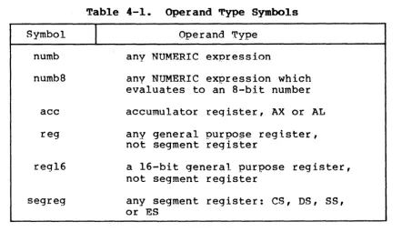
The instruction-defini tion tables organize ASM-86 instructions into functional groups. Within each table, the instructions are listed alphabetically. ~able 4-1 shows the symbols used in the instruction-definition tables to define operand types.
Symbol
numb
numb8
acc
reg
regl6
segreg
Table 4-1. Operand Type Symbols
I
Operand Typeany NUMERIC expression
any NUMERIC expression which evaluates to an 8-bit number
accumulator reqister, AX or AL
any general purpo~e register, not segment register
a 16-bit general purpose register, not segment register
[image:40.618.103.546.446.701.2]CP/M-86 Programmer's Guide 4.1 Introduction
Symbol
I
mem
simpmem
mem
I
regmem
I
reg16label
lab8
Table 4-1. (continued)
Operand Type
any ADDRESS expression, with or without base- and/or index-addressing modes, such as:
variable variable+3 variable[bx] variable[SI] variable[BX+SI]
[BX] [BP+DI]
any ADDRESS expression WITHOUT base-and index- addressinq modes, such as:
variable variable+4
any expression symbolized by "req" or "mem"
any expression symbolized by "mem
I
reg", but must be 16 bi tsany ADDRESS expression which evaluates to a label
any "label" which is within
+1-
128bytes distance from the instruction
The 8086 CPU has nine single-bit Flag registers which reflect the state of the CPU. The user cannot access these registers directly, but can test them to determine the effects of an executed
instruction ul?on an operand or register. The effects of
[image:41.618.96.528.54.472.2]CP!M-86 Programmer~s Guide 4.1 Introduction
Table 4-2. Flag Register Symbols
AF Auxiliary-Carry-Flag
CF Carry-Flag
OF Direction-Flag
IF Interrupt-Enable-Flag
OF Overflow-Flag
PF Parity-Flag
SF Sign-Flag
TF Trap-Flag
ZF Zero-Flag
4.2 Data Transfer Instructions
There are four classes of data transfer operations: general purpose, accumulator specific, address-object and flag. Only SAHF and POPF affect flag settings. Note in Table 4-3 that if acc
=
AL, a byte is transferred, but if acc=
AX, a word is transferred.IN
IN
LAHF
LOS
LEA
LES
MOV
MOV
Table 4-3. Data Transfer Instructions
Syntax
acc,numb81numb16
acc,OX
reg16,mem
reg16,mem
reg16,mem
req,memlreg
memlreg,reg
I
Resulttransfer data from input port given by numb8 or numb16 (0-255) to
accumulator
transfer data from input port given by DX register (O-OFFFFH) to
accumulator
transfer SF, ZF, AF, PF, and CF flags to the AH register
transfer the segment part of the memory address (DWORD variable) to
the DS segment register, transfer the offset part to a general
purpose 16-bit register
transfer the offset of the memory address to a (16-bit) register
transfer the segment part of the memory address to the ~s segment
reqister, transfer the offset part to a 16-bit general purpose register
move memory or register to reqister
CP/M-86 Programmer~s Guide 4.2 Data Transfer Instructions
Table 4-3. (continued)
Syntax
MOV mem I reg, numb
MOV segreg,memlreg16
MOV memlreg16,segreg
OUT numb8lnumb16,acc
OUT DX,acc
POP memlreg16
POP segreg
POPF
PUSH mem
I
regl6PUSH segreg
PUSHF
SAHF
XCHG reg,memlreg
XCHG memlreg,reg
XLAT mem
I
regI
Resultmove immediate data to memory or register
move memory or register to segment register
move segment register to memory or register
transfer data from accumulator to output port (0-255) given by numb8 or numbl6
transfer data from accumulator to output port (O-OFFFFH) given by DX register
move top stack element to memory or register
move top stack element to segment register; note that CS segment register not allowed
transfer top stack element to flags
move memory or register to top stack element
move segment register to top stack element
transfer flags to top stack element
transfer the AH register to flags
exchange register and memory or register
exchange memory or register and reqister
CP/M-86 Programmer~s Guide 4.3 Arithmetic, Logic, and Shift
4.3 Arithmetic, Logical, and Shift Instructions
The 8086 CPU performs the four basic mathematical operations in several different ways. It supports both 8- and l6-bit operations and also signed and unsigned arithmetic.
Six of the nine flag bits are set or cleared by most arithmetic operations to reflect the result of the operation. Table 4-4 summarizes the effects of arithmetic instructions on flag bits. Table 4-5 defines arithmetic instructions and Table 4-6 logical and shift instructions.
Table 4-4. Effects of Arithmetic Instructions on Flags
CF is set if the operation resulted in a carry out of (from addition) -or a borrow into (from subt"raction) the high-order bit of the result; otherwise CF is cleared.
AF is set if the operation resulted in a carry out of (from addition) or a borrow into (from subtraction) the low-order four bits of the result; otherwise AF is cleared.
ZF is set if the result of the o-peration is zero; otherwise ZF is cleared.
SF is set if the result is negative.
PF is set if the modulo 2 sum of the low-order eight bits of the result of the operation is 0 (even parity); otherwise PF is cleared (odd parity).
[image:44.626.74.519.208.685.2]CP/M-86 AAA AAD AAM AAS ADC ADC ADC ADD ADD ADD CBW CWO CMP CMP CMP OAA DAS
Programmer~s Guide
Table Syntax reg,memlreg memlreg,reg memlreg,numb req,memlreg memlreg,reg
mem
I
reg ,numbreg,mem!reg
memlreg,reg
memlreg,numb 4-5.
I
4.3 Arithmetic, Logic, and Shift
Arithaetic Instructions
Result
adjust unpacked BCD (ASCII) for addition - adjusts AL
adjust unpacked BCD (ASCII) for division - adjusts AL
adjust unpacked BCD (ASCII) for multiplication -"adjusts AX
adjust unpacked BCD (ASCII) for subtraction - adjusts AL
add (with carry) memory or register to register
add (with carry) register to memory or register
add (with carry) immediate data to memory or register
add memory or register to register
add register to memory or register
add immediate data to memory or register
convert byte in AL to word in AH bv sign extension
convert word in AX to double word in DX/AX by sign extension
compare register with memory or register
compare memory or register with register
compare data constant with memory pr register
decimal ad;ust for addition, ad;usts AL
[image:45.626.57.546.52.726.2]CP/M-86 Programmer~s Guide 4.3 Arithmetic, Logic, and Shift
Table 4-5. (continued)
INC
DIV
IDIV
IMUL
MUL
NEG
SBB
SBB
SBB
SUB
SUB
SUB
Syntax
meml reg
meml reg
mem' reg
meml reg
mem
I
regmem
I
regreg ,mem
I
regmem
I
reg, regmem
I
reg, numbreg,memlreg
mem
I
reg, regmem
I
reg, numbI
Resultadd I to memory or register
divide (unsigned) accumulator (AX or AL) by memory or register.
If byte results, AL
=
quotient, AR=
remainder. If word results, AX=
quotient, OX=
remainderdivide (signed) accumulator (AX or AL) by memory or register
-quotient and remainder stored as in
DIV
multiply (signed) memory or register by accumulator (AX or AL) - if byte, results in AH, AL. If word, results in DX, AX
multiply (unsigned) memory or register by accumulator (AX or AL) - results stored as in IMUL
two~s complement memory or register
subtract (with borrow) memory or register from register
subtract (with borrow) register from memory or register
subtract (with borrow) immediate data from memory or register
subtract memory or register from register
subtract register from memory or register
[image:46.629.58.549.58.657.2]CP/M-86 Programmer~s Guide 4.3 Arithmetic, Logic, and Shift
Table 4-6.
Syntax
AND reg,memlreg
AND mem!reg,reg
AND memlreg,numb
NOT mem! reg
OR reg,memlreg
OR mem' reg, reg
OR memlreg,numb
RCL mem
I
reg,1RCL memlreg,cL
RCR memlreg,1
RCR memlreg,CL
ROL mem
I
reg,lROL memlreq,CL
ROR mem
I
reg,lROR memlreg,CL
SAT .. memlreq,l
I
Logic and Shift Instructions
Result
perform bitwise logical "and" of a register and memory register
perform bitwise logical "and" of memory register and register
perform bitwise logical "and" of memory register and data constant
form ones complement of memory or register
perform bitwise logical "or" of a register and memory register
perform bitwise logical "or" of memory register and register
perform bitwise logical "or" of memory register and data constant
rotate memory or register 1 bit left through carry flag
rotate memory or register left through carry flag, number of bits given by CL reqister
rotate memory or register 1 bit right through carry flag
rotate memory or register right through carry flag, number of bits given by CL register
rotate memory or register 1 bit left
rotate memory or register left, number of bits given by CL register
rotate memory or register 1 bit .right
rotate memory or register right, number of bits given by CL register
[image:47.629.49.547.58.713.2]