6
I
January 2018
Performance Enhancement Analysis of Double
Effect Vapor Absorption System Using Loop Heat
Pipes
Ankit Dwivedi1, R S Mishra2
1, 2
Dept. of Mechanical Engineering, Delhi Technological University, Delhi
Abstract: A high temperature heat source cannot be used efficiently for a single effect vapor absorption refrigeration system (VARS). For the utilization of such high temperature source a double effect system can be brought into action. The COP I and COP II of a double effect VARS are generally higher than that of the single effect system. This research work implements some major modifications with the use of a Loop Heat Pipe (LHP) in the design of the double effect VARS to attain an enhanced performance. The simulations have found that the improved COP I and COP II are 2.09 and 0.4571 respectively. Also the percentage increase on the modified system has been recorded as 75.82% and 28.2 % respectively. Simulations also found that
the average TC can be maintained at 104.2ºC. The increase in the performance characteristics shows a positive gradient with the
increase in the temperature of operation of LHP.
I. INTRODUCTION
[image:2.612.163.449.437.553.2]The fundamental of loop heat pipes(LHP) (Fig 1) is evaporation and condensation. On the heated side ‘1’, the working liquid evaporates and on the cool side’3, 4, 5’ it condenses. As every material has different properties (section A-A), it is required to choose the set of material properly. At the source the cool fluid is evaporated, the hot vapor stream is later moved to the sink through the vapor line’2’, where the vapor condenses again and is transported back to the source through liquid line ‘5’. Highly efficient heat exchange is a direct result of the low heat resistance of vapors. This low heat resistance is because of little effective length of heat exchange through strong porous wick walls.
Fig 1: Cyclic process of a Loop Heat Pipe [35]
The LHPs have an inverted wick (Fig 2), and the vapors are located adjacent to the heated surface. These wicks are prepared by power metallurgy. The outer surface of the wick is in contact with the heated surface. Circumferential and axial grooves are required to generate flow channels for the vapors flow which can be machined in the wick, or to the evaporator body.
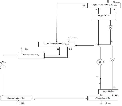
[image:2.612.123.474.610.724.2]The single effect VARS is not well suited for the utilization of heat from a source with temperature higher than a certain temperature (The COP decreases with increase in temperature beyond a certain point). Hence the requirement of Double Effect VARS(Fig.3) is realised.
II. LITERATURE REVIEW
Fabian Korn et al. [2012]performed several vital experiments on heat pipes to establish it to be one of the most effective procedures to transport thermal energy from one point to another, mostly used for cooling[6].Sameer Khandekaret al.[2010]performed experiments on the global thermal performance modeling of Pulsating Heat Pipes (PHPs) requires local, spati-o-temporally coupled, flow and heat transfer information during the characteristic, self-sustained thermally driven oscillating Taylor bubble flow, under different operating conditions[7].JozefHužvár, Patrik Nemecet al. [2007]used heat pipe, observed its basic principles and operating limits. High temperature heat pipes were evaluated for use in energy conversion applications such as fuel cells, gas turbine re-combustors, and Stirling cycle heat sources, with the resurgence of space nuclear power, additional applications include reactor heat removal elements and radiator elements[8].R.Z. Wanget al.[2008]added heat pipes in adsorption water chiller or ice maker initials. His work showed that the adsorption refrigerators are very efficient [10].Pracha Yeunyongkul et al.[2009]aimedat experimentally investigating the application of a closed loop oscillating heat pipe (CLOHP) as the condenser for a vapor compression refrigeration system[14].R. Rajashree et al.[1990]went through a numerical analysis of an unsteady, viscous, laminar, incompressible, two dimensional heat and mass transfer, in the vapor gas region of gas loaded circular heat pipe [20]. Da-Wen Sun (1996) performed a detailed thermodynamic analysis of the properties of these binary fluids and expressed in polynomial equations. The performances of three cycles were compared. M.M. Talbi et al. (2000) carried out an exergy analysis on a single-effect absorption refrigeration cycle with lithium-bromide±water as the working Fuid pair. E. Kurem et al.(2001) analyzed the Absorption Heat Pump (AHP) and Absorption Heat Transformers (AHT) using ammonia-water and water-lithium bromide solutions. A fundamental AHP and AHT systems was described and explained the operating sequence. R.D. Misra et al. (2002) applied the therm-o-economic theory is to the economic optimization of a single effect water/LiBrvapor absorption refrigeration system for air-conditioning application. S.A. Adewusi et al (2004). studied the performance of single-stage and two-stage ammonia–water absorption refrigeration systems (ARSs).They calculated entropy generation of each component and the total entropy generation of all the system components as well as COP of the ARSs . S. Arivazhagan et al. (2006) investigated experimentally on the performance of a two-stage half effect vapor absorption cooling system .The prototype is designed for 1 kW cooling capacity using HFC based working fluids (R134a as refrigerant and DMAC as absorbent). Rabah Gomri et al. (2008) performed exergy analysis of double effect lithium bromide/water absorption refrigeration system. The system consisted of a second effect generator between the generator and condenser of the single effect absorption refrigeration system, including two solution heat exchangers between the absorber and the two generators. S.C. Kaushik et al. (2009) presented the energy and exergy analysis of single effect and series flow double effect water–lithium bromide absorption systems. They developed a computational model for the parametric investigation of the systems. Berhane H. Gebreslassie et al. (2010) performed an exergy analysis, which only considered the unavoidable exergy destruction, conducted for single, double, triple and half effect Water–Lithium bromide absorption cycles. Gulshan Sachdeva et al.(2014) performed anexergy analysis of VAR system using LiBr-H2O as working fluid with the modified Gouy-Stodola approach. Karl Ochsner (2008)et al. (2008) developed a new CO2-heat pipe with high-grade steel corrugated pipe system, which – contrary to other pipe systems permits raw length up to 100 m. They also described the establishment of the heat pump system in general. Research works have thoroughly studied thermodynamic and thermo-economic problems of the various VARS, namely half; single, double, triple effects etc. Some works have already done the exergetic analysis of the VAR systems. They work on the heat input, so these systems can be interconnected with other power generating systems, using the waste heat of the power development cycles. Also the heat is rejected from the condenser of VARS while the rich refrigerant is condensed. This heat can also be used to reduce the actual heat input in the generator. In the research work LHP can be used as the new component to be used for intra-cycle heat exchange and reduce the requirement of heat input for the cycle to operate. The LHP acts as a super conductor owing to its high heat transfer coefficients associated with the boiling and condensation. Also replacements of other bulky components by the LHP can be done, which would reduce the cost and size of the system.
III. SYSTEMS DESCRIPTION
temperature, condenser temperature, and absorber temperature) and three pressure levels (low pressure in the evaporator and absorber, medium pressure in the condenser and the low pressure generator, the high pressure in the high pressure generator). The strong solution is pumped to the HPG where it is heated to boil out the refrigerant vapor from the solution. The primary vapor, from the HPG moves to the LPG heating the medium concentration solution and then it’s condensed. The heat of condensation of the primary vapor from the HPG is used in the LPG to get the secondary vapor. Thus, the total amount of liquid refrigerant leaving condenser is the sum of refrigerant originating from HPG and LPG. The refrigerant from the condenser expands into the evaporator where it extracts the heat of vaporization and cools the ambient. [7]
Fig 3: A Double Effect (Series)Vapor Absorption System
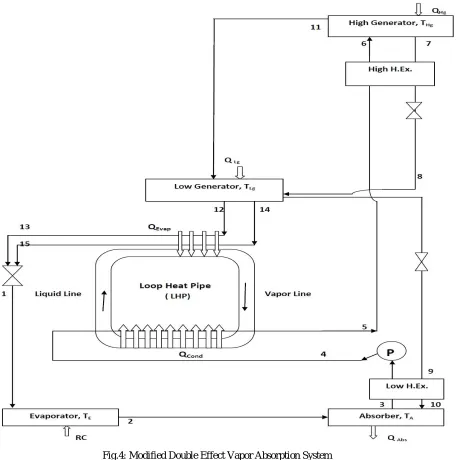
Fig.4: Modified Double Effect Vapor Absorption System
Table 1: Terms Used in Simulation
Terms Abbreviations
Refrigeration Effect in kW RE (kW)
Heat rejected in absorber in kW Qa(kW)
Heat supplied in generator in kW Qg (kW)
Heat rejected in condenser of LHP in kW Qcond(kW)
Heat absorbed in evaporator of LHP in kW Qeva(kW)
Absorber Temperature in°C TLa,THa(°C)
Generator Temperature in °C THg, TLG (°C)
LHP Condenser Temperature in °C Tc (°C)
Evaporator Temperature in °C TE,Te(°C)
[image:5.612.80.530.564.732.2]First Law Coefficient of Performance COP I Second Law Coefficient of Performance COP II
Heat Leaked from the LHP in kW QLeak (kW)
Percentage Improvement in First Law Coefficient of Performance
%COP I imp
Percentage Improvement in Second Law Coefficient of Performance
%COP II imp
Improvement in First Law Coefficient of Performance
COP I imp
Improvement in Second Law Coefficient of Performance
COP II imp
Low Pressure Generator LPG
High Pressure Generator HPG
IV. RESULTS AND DICSUSSIONS
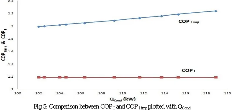
[image:6.612.116.510.317.504.2]The Fig 5,6 and 7 show the variation of COP I& COP II with the heat being utilized in the LHP QCond. Fig 5 shows the comparison COP I of the modified system with the basic system.
Fig 5: Comparison between COP I and COP I imp plotted with QCond
[image:6.612.108.514.525.723.2]The average enhanced COP I for the modified system is 2.09 where as the COP I of the basic system is 1.189.
The fig 6 describes the variation of COP II of the modified system with the basic system. The average COP II upon this modification is 0.4571, where the original COP IIis 0.3557.
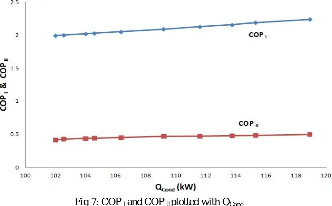
Fig 7: COP I and COP IIplotted with QCond
The fig 7 compares the COP I and the COP II of the modified system with a variable QCond. It can be seen that the increase in the performance parameters is gradual and consistent. More the heat utilized with the help of LHP, higher are the performances based on First law and Second law. It can be said that a modification inside the LHP will help in enhancing the performance. Fig 8, 9 and 10 help in analysing the %age improvement happening due to the modification of the system. Fig 8 shows the variation with the QCond. The COP II has a sharper rise over the range when compared to the COP I.
Fig8: Variation of %COP I imp and % COP II imp plotted with QCond
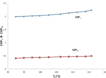
The fig 9 shows the %age rise in COP I and COP II with varying TC. The COP I shows a increasing slope for the entire range while the COP II shows a decreasing slope. Further increase in the TC may not result in the in the enhancement in the COP II, as the COP I will show improvement for further increase in TC. The average %age increase in COP I is 75.82.
[image:8.612.129.495.182.414.2]Here fig 10 shows the variation of the above with a range of TG. The trending is similar to that of fig 9. With the increase in the TG the COP I is expected to increase (Fig 12). But with the rise in TG also there will be a rise in Evaporator temperature of LHP along with the rise in TC and decrease in the QLeak, hence the utilization of heat will increase. Along with this increases the COP II (Fig 11). The %age increase in COP II is 28.5.
Fig 10: Comparison of %age improvements in COP I& COP II varying the TG
[image:8.612.124.496.442.715.2]Fig 12: Comparison of COP I& COP II varying the TG
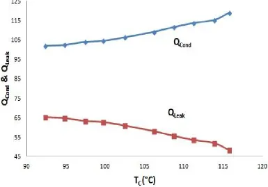
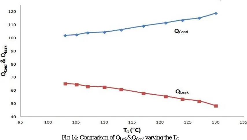
It has been observed that with increase in the TG, COP I, COP II and TC all increase. Fig 13 and fig 14 show the variation of QCond and QLeak with TC and TG respectively. In both the figures it can be easily noticed that the increase in the temperature provides desirable results such as reduction in the QLeak and increase in QCond.
[image:9.612.120.505.439.708.2]Fig 14: Comparison of QLeak&QCond varying the TG
[image:10.612.119.504.385.676.2]The QCond has a positive gradient in both the figures. Further increase in the temperature will increase the QCond and hence the leakage of heat will decrease. The limit of the temperature is 130ºC; other methods have to be sorted out to increase the QCond, such as changing the material and changing the arrangements of heat transfer surface of the LHP.
Fig 15: Variation of TC with the TG
V. CONCLUSIONS
Following the results of the simulations, following conclusions can be made:
A. The average enhanced COP I &COP II are 2.09 and 0.4571 respectively.
B. The percentage increase in COP I &COP II can be observed to be 75.82 and 28.2 respectively. C. The COP II has a sharper rise over the range when compared to the COP I for the range of QCond.
D. The COP I shows a increasing slope for the entire range while the COP II shows a decreasing slope for the entire range of the
TG and TC.
E. Increase in the temperature TG provides the desirable results such as reduction in the QLeak and increase in QCond and average TC is found to be is 104.23 ºC .
REFERENCES
[1] Saeed. Sedigh , Hamid. Saffari ,”Thermodynamic analysis of single effect and half effect absorption refrigeration system” International Journal of Energy & Technology Vol.25 (2011) 1-9.
[2] S. Arivazhagan , R. Saravanan , S. Renganarayanan ,” Experimental studies on HFC based two-stage half effect vapor absorption cooling system” Applied Thermal Engineering Vol. 26 (2006) 1455–1462.
[3] GulshanSachdeva, Ram Bilash,” Thermodynamic Analysis of a Vapor Absorption System Using Modified Gouy-Stodola Equation” International Journal of Computer, Electrical, Automation, Control and Information Engineering Vol:8, No:12, 2014.
[4] I. Horuz,” A comparison between Ammonia-water and Water-Lithium Bromide solutions in Vapor Absorption Refrigeration Systems” Int. Comm. Heat Mass Transfer, Vol. 25, No. 5, pp. 711-721, 1998.
[5] Abdul Khaliq, and Rajesh Kumar,” Exergy analysis of double effect vapor absorption refrigeration system” Int. J. Energy Res. 2008; Vol.32:161–174. [6] S.C. Kaushika, AkhileshArora,” Energy and exergy analysis of single effect and series flow double effect water–lithium bromide absorption refrigeration
systems” international journal of refrigeration Vol.32 ( 2009 ) 1247 – 1258.
[7] RabahGomri , RiadHakimi,” Second law analysis of double effect vapor absorption cooler system” Energy Conversion and Management Vol.49 (2008) 3343– 3348.
[8] S.A. Adewusi, Syed M. Zubair,” Second law based thermodynamic analysis of ammonia–water absorption systems” Energy Conversion and Management Vol. 45 (2004) 2355–2369.
[9] RabahGomri,” Second law comparison of single effect and double effect vapor absorption refrigeration systems” Energy Conversion and Management Vol. 50 (2009) 1279–1287.
[10] R.D. Misra, P.K. Sahoo, S. Sahoo, A. Gupta,”Thermoeconomic optimization of a single effect water/LiBrvapor absorption refrigeration system” International Journal of Refrigeration Vol.26 (2003) 158–169.
[11] M. Belghazi, A. Bontemps, C. Marvillet,” Experimental study and modelling of heat transfer during condensation of pure fluid and binary mixture on a bundle of horizontal finned tubes” International Journal of Refrigeration Vol.26 (2003) 214–223.
[12] M.M. Talbi, B. Agnew,” Exergy analysis: an absorption refrigerator using lithium bromide and water as the working Fuids” Applied Thermal Engineering Vol. 20 (2000) 619-630.
[13] E. Kurem,” A comparison between Ammonia-water and Water-Lithium Bromide solutions in vapor absorption heat transformers “In. Comm. Heat Mass Transfer; Vol. 28, No. 3, pp. 421-438, 2001.
[14] Da-Wen Sun,” Comparison of the performances and NH3-H20, NH3-LiNO3 and NH3-NaSCN Vapor Absorption Refrigeration Systems” Energy Convers. Mgmt Vol. 39, No. 5/6, pp. 357-368, 1998.
[15] Yu.F. Maydanik,” Review Loop heat pipes” Applied Thermal Engineering Vol.25 (2005) 635–657.
[16] Randeep Singh, AliakbarAkbarzadeh , MasatakaMochizuk,” Operational characteristics of a miniature loop heat pipe with flat evaporator” International Journal of Thermal Sciences Vol.47 (2008) 1504–1515.
[17] T.X. Li, R.Z. Wang , L.W. Wang, Z.S. Lu, C.J. Chen,” Performance study of a high efficient multifunction heat pipe type adsorption ice making system with novel mass and heat recovery processes” International Journal of Thermal Sciences Vol.46 (2007) 1267–1274
[18] Yuan-Ching Chiang , Wen-Cheng Kuo , Chia-Che Ho , Jen-JieChieh,” Experimental study on thermal performances of heat pipes for air-conditioning systems influenced by magnetic nanofluids, external fields, and micro wicks” International Journal of Refrigeration Vol.43 ( 2014 ) 62 -70.
[19] T.X. Li, R.Z. Wang, L.W. Wang, Z.S. Lu,” Experimental investigation of an innovative dual-mode chemisorption refrigeration system based on multifunction heat pipes” International Journal of Refrigeration 3 1 ( 2 0 0 8 ) 1 1 0 4 – 1 1 1 2.
[20] L. GarousiFarshi a,*, C.A. Infante Ferreira b, S.M.S. Mahmoudi a, M.A. Rosen,” First and second law analysis of ammonia/salt absorption refrigeration systems” International Journal of Refrigeration Vol. 4 0 ( 2 0 1 4 ) 1 1 1-1 2 1.
[21] T.X. Li, R.Z. Wang , L.W. Wang, Z.S. Lu, J.Y. Wu,” Influence of mass recovery on the performance of a heat pipe type ammonia sorption refrigeration system using CaCl2/activated carbon as compound adsorbent” Applied Thermal Engineering Vol. 28 (2008) 1638–1646.
[22] Z.S. Lu , L.W. Wang, R.Z. Wang,” Experimental analysis of an adsorption refrigerator with mass and heat-pipe heat recovery process” Energy Conversion and Management Vol. 53 (2012) 291–297.
[23] Behrooz M. Ziapour*, Mohsen Tavakoli,” Performance study on a diffusion absorption refrigeration heat pipe cycle” International Journal of Thermal Sciences Vol.50 (2011) 592-598.
[25] Behrooz M. Ziapour*, Mohsen Tavakoli,” Performance study on a diffusion absorption refrigeration heat pipe cycle” International Journal of Thermal Sciences 50 (2011) 592-598.
[26] T.S. Jadhav , M.M. Lele,” Theoretical energy saving analysis of air conditioning system using heat pipe heat exchanger for Indian climatic zones” Engineering Science and Technology, an International Journal Vol. 18 (2015) 669-673.
[27] Chengchu Yan , Wenxing Shi , Xianting Li , Shengwei Wang,” A seasonal cold storage system based on separate type heat pipe for sustainable building cooling” Renewable Energy Vol.85 (2016) 880-889.
[28] Matthias H. Buschmann,” Nanofluids in thermosyphons and heat pipes: Overview of recent experiments and modelling approaches” International Journal of Thermal Sciences Vol.72 (2013) 1-17.
[29] P.D. Dunn, D.A. Reay, Heat Pipes, Pergamon Press, Oxford, 1993.
[30] D.Reay, Heat Pipes-Theory, Design and Applications, Butterworth-Heinemann,Oxford, Fifth edition 2006.
[31] Korn, F., “Heat Pipes and its Applications” Project Report 2008 MVK160 Heat and Mass Transport May 07, 2008, Lund, Sweden.
[32] Rajashree, R., Rao, K.S., “A Numerical Study of the Performance of Heat Pipe” Indian Journal of Pure and Applied Mathematics, 21 (1): 95-108, January 1990.
[33] C.P. Arora, Refrigeration and Air Conditioning, Tata Mcgraw-Hill Publishing Company Limited,Delhi, Third Edition, 2009.
[34] Ankit Dwivedi, R. S. Mishra,” Thermodynamic Analysis of Heat Pipe Using Ammonia, Water and Ethanol with a View to Being Used in Refrigeration” ISSN 2347 - 3258 International Journal of Advance Research and Innovation, Volume 3, Issue 3 (2015) 498-502.
[35] Ankit Dwivedi, R. S. Mishra, Manjunath K,”Optimization of Vapor Absorption System Using Heat Pipes” ISSN: 2321-9653 International Journal for Research in Applied Science & Engineering Technology (IJRASET), Volume 5 Issue VIII, August 2017,634-639.
![Fig 2: Porous Wick in the LHP[35].](https://thumb-us.123doks.com/thumbv2/123dok_us/8296329.852987/2.612.163.449.437.553/fig-porous-wick-in-the-lhp.webp)