© 2017, IRJET | Impact Factor value: 5.181 | ISO 9001:2008 Certified Journal
| Page 264
Modal Analysis of Single Rectangular Cantilever Plate by
Mathematically, FEA and Experimental
Ashish R. Sonawane
1, Poonam S. Talmale
21
Research scholar, Late G. N. Sapkal College of Engineering, Nashik, Maharashtra, India
2Assistant Professor, Late G. N. Sapkal College of Engineering, Nashik, Maharashtra, India
---***---Abstract -
Modal analysis is a major technique to determine the vibration characteristics of engineering structures and its component’s. It is process by which the natural frequencies, mode shapes and damping factor of structure can be determined with a relative ease. It should be a major alternative to provide a helpful contribution in understanding control of many vibration phenomenons which encompasses in practice. In this work we compared the natural frequency mathematically, FEA and experimentally. The main objective of this paper is to determine the natural frequency and mode shape of a single rectangular cantilever beam condition and to compare the results obtained by finite element analysis with experimental results. The cantilever beam of rectangular plate is designed and analyzed in ANSYS. A good correlation between the mathematical, FEA and experimental result is observed. The analysis result helps in depicting the failure loads for different conditions. Aluminum single rectangular cantilever plate is studied in this work. For mathematically Euler’s Bernoulli’s beam theory is used. The results obtained by both the methods are found to be satisfactory.Key Words: Natural frequency, mode shapes, FEA.
1. INTRODUCTION
The aim of this paper is to provide efficient numerical techniques for the prediction of the dynamic response of single rectangular cantilever plate and to validate the predictions via experimental tests. Vibration problems are often occurred in mechanical structure. The structure itself has a certain properties so it is necessary to understand its characteristics. Especially in lightweight structures, these additional contributions strongly affect the modal properties of the overall structure and cannot be neglected. At the same time, the precise knowledge of the modal properties is the starting point for controllers design. In this work a modal analysis by finite element method is used. The main purpose of modal analysis is to study the dynamic properties of structures like natural frequency, damping and mode shapes. In the present paper, we examine and compare different techniques for modal analysis of simple rectangular cantilever beams. The first technique is based on mathematical modeled by the Euler–Bernoulli beam theory. Next, we test obtaining a finite-dimensional version of the system finite-element
(FEA) method. The ABAQUS FEA software was used to predict the natural frequencies, mode shapes. After completing these two analysis, it is necessary to carry experimental modal analysis to compare the results and to analyze it for validation. An experimental set up is prepared with the help of NI-Lab View software and data acquisition hardware to obtain natural frequencies and mode shapes. In this paper, we will be formulating the equations of motion of a free cantilever beam. The natural frequency of continuous beam system will be found out different variables of beam using ANSYS 14.0. The results compared with mathematically, FEA and experimentally with each other.The modal analysis is used to understand the dynamic properties of structure such as natural frequency, damping ratio and mode shape. With modal analysis, the modal parameters of the structures can be extracted. The modal parameters, including natural frequency, damping ratio, and mode shape, are the fundamental elements that describe the movement and response of a structures to free vibrations. After completing these two analysis, it is necessary to carry experimental modal analysis to compare the results and to analyze it for validation. So knowing these modal parameters helps to understand the structure’s response to free vibration conditions as well as to perform design validation.
2. LITERATURE SURVEY
Before starting with actual working, it’s always helpful to study literature and work which is already carried out in similar field. This study helps to decide the project outline and flow. Some research papers, case study have discussed.
Xiaocong He [1] Investigated the dynamic response of a single rectangular plate numerically using ABAQUS software & experimentally and compared both the results with each other. The LMS CADA-X dynamic test software and LMS DIFA Scads II 48 channels data acquisition hardware is used in experimental measurements of vibration of the beams. The comparable results are obtained between the experimentally measured and predicted dynamic response of the beams.
© 2017, IRJET | Impact Factor value: 5.181 | ISO 9001:2008 Certified Journal
| Page 265
adhesive, but do not appear to change significantly with an increase in the poisons ratio. The investigations are carried out using finite element method (FEM).
Yu Du, Lu Shi, [3] prepared the FE model for the specimen used in this study was developed in the commercial FE package ABAQUS. Validate with FEA and Experimentally Ankit Gautam, Jai kumar Sharma, Pooja Gupta [4] the theoretical and numerical modal analysis of beam are performed. The numerical results are obtained using ANSYS 14.5. The numerical and theoretical results are found to have extremely good correlation.
Dr. Negahban [5] Beam studied in this paper are long, thin, cantilever beam. Determine the equation vibration of beams. Euler–Bernoulli beam theory is used.
Subhransu Mohan Satpathy, Praveen Dash [6] formulating the equations of motion of a free cantilever beam. The natural frequency of continuous beam system will be found out at different variables of beam using ANSYS 14.0. The results will be compared further using experimentation by free vibration of a cantilever beam. Using those results, able to compare the parameters in Euler-Bernoulli.
3. MATHEMATICAL MODAL ANLYSIS
Euler–Bernoulli beam theory is used get natural frequency of rectangular cross sectioned cantilever plate subjected to natural vibration.
Consider an Euler-Bernoulli uniform cantilever beam undergoing transverse vibration.
Fig -1: A cantilever beam
Nomenclature:
L = 1000mm Length of beam
b = 50mm Width of beam
h = 5mm Thickness of beam
E = 70 x 103 (N/mm2) Young’s modulus of Aluminum
v = 0.35 Poisons ratio of Aluminum
ρ = 2700 (Kg/m3) Density of Aluminum
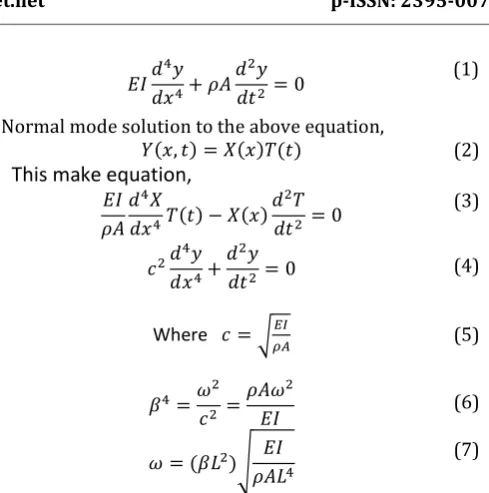
Using Euler- Bernoulli Beam Theory,
(1)
Normal mode solution to the above equation,
( ) ( ) ( ) (2)
This make equation,
( ) ( )
(3)
(4)
Where √ (5)
(6)
( )√
(7)
Where
(1.875, 4.694, 7.855, 10.996, 14.143, 17.286, 20.429, 23.571 etc)
Now, to find the natural frequencies for different modes,
1. First Natural Frequency
√
√
We know,
2
n nf
2. Second Natural Frequency
√
√
[image:2.595.308.553.71.318.2]
© 2017, IRJET | Impact Factor value: 5.181 | ISO 9001:2008 Certified Journal
| Page 266
2
n nf
3. Third Natural Frequency
√
√
13.24 rad/sec We know
2
n nf
4. Fourth Natural Frequency
√
√
28.094 rad/sec We know
2
n nf
5. Fifth Natural Frequency
√
√
We know
2
n nf
Similarly, we can calculate natural frequencies for remaining modes by this method. It is possible to compare all natural frequencies with the software analysis as well
[image:3.595.323.525.179.329.2]as the experimental modal analysis. The results of theoretical natural frequencies obtained by using material properties and dimensions of the beam.
Table -1: Theoretical natural frequencies of rectangular cross sectioned cantilever plate
Mode
Shapes Natural Frequencies
1 0.135
2 0.81
3 2.1
4 4.47
5 7.39
6 11.04
7 15.43
8 20.55
9 24.54
10 28.87
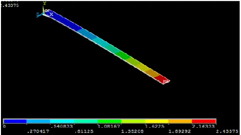
4. Finite Element Modeling
Modeling of single rectangular cantilever plate was done with the help of CATIA software. Finite element model of beam is constructed in ANSYS and then computational modal analysis is performed to generate natural frequencies and mode shapes. The material parameter is taken from nomenclature of fig 1. Boundary conditions are applied at end of beam. finite element analysis (FEA) of specified objects are carried out to obtain necessary parameters and the specimens are to be tested in the software to analyze the dynamic response of the specimen at cantilever beam condition and to get the natural frequencies and mode shapes. Solving a practical problem by FEA involves learning about the program, preparing a mathematical model, discretizing it, doing the calculations and checking the results.
[image:3.595.310.558.552.691.2]© 2017, IRJET | Impact Factor value: 5.181 | ISO 9001:2008 Certified Journal
| Page 267
Fig -3: Second mode shape of rectangular cross sectioned cantilever plate
Fig -4: Third mode shape of rectangular cross sectioned cantilever plate
Fig -5: Fourth mode shape of rectangular cross sectioned cantilever plate
Fig -6: Fifth mode shape of rectangular cross sectioned cantilever plate
[image:4.595.356.509.101.272.2]Similarly, we can calculate natural frequencies for remaining modes by this method.
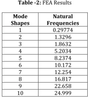
Table -2: FEA Results
Mode
Shapes Frequencies Natural
1 0.29774 2 1.3296 3 1.8632 4 5.2034 5 8.2374 6 10.172 7 12.254 8 16.817 9 22.658 10 24.999
5. EXPERIMENTAL ANALYSIS
The basic experimental setup is shown in fig 7. The point of impact and position of the accelerometer are chosen such a way that the natural frequencies of the system can be easily determined.
Fig -7: Experimental set up
The equipment’s which are used to perform the real experiments are as follows.
1. Impact Hammer 2. Accelerometer
3. Data Acquisition Hardware (At least 2-Channel.) 4. A PC or a Laptop loaded with NI-Lab View
software for modal analysis.
5. Power supply for the PC and vibration analyzer, connecting cables for the impact hammer and accelerometer and adhesive/wax to fix the accelerometer.
5.1 Experimental Procedure
[image:4.595.30.282.105.218.2] [image:4.595.35.283.264.369.2] [image:4.595.307.563.364.513.2] [image:4.595.35.283.415.522.2] [image:4.595.34.285.567.679.2]© 2017, IRJET | Impact Factor value: 5.181 | ISO 9001:2008 Certified Journal
| Page 268
2. One end of the beam was clamped as the cantilever beam support.
3. An accelerometer (with magnetic base) was placed at the free end of the cantilever beam, to observe the free vibration response.
4. An initial deflection was given to the cantilever beam and allowed to oscillate on its own. To get the higher frequency it is recommended to give initial displacement at an arbitrary position apart from the free end of the beam (e.g. at the mid span).
5. This could be done by bending the beam from its fixed equilibrium position by application of a small static force at the free end of the beam and suddenly releasing it, so that the beam oscillates on its own without any external force applied during the oscillation.
6. The free oscillation could also be started by giving a small initial tap at the free end of the beam. 7. The data obtained from the chosen transducer
was recorded in the form of graph.
8. The procedure was repeated for 5 to 10 times to check the repeatability of the experimentation. 9. The whole set of data was recorded in a data base.
[image:5.595.307.559.131.461.2]By using experimental procedure we find natural frequencies and mode shapes of single rectangular plate which is helpful to validate with mathematical and FEA modal analysis.
Table -3: Experimental natural frequencies
Mode
Shapes Frequencies Natural
1 0.233
2 1.142
3 1.737
4 4.799
5 8.32
6 9.36
7 11.67
8 15.013
9 23.617
10 23.944
6. RESULT AND DISCUSSION
[image:5.595.62.234.472.623.2]In this work, theoretical modal analysis of single rectangular cantilever plate has been carried out in various conditions and natural frequencies are obtained. The theoretical results are validating with ANSYS 14.0 software and experimental results. From this analysis it is observed that the natural frequencies obtained are almost close to each other except the 20 % of the error
.
Table -1: Comparative table of natural frequencies at each node
Mode Theoretical FEA Experimental
1 0.135 0.29774 0.233
2 0.81 1.3296 1.142
3 2.1 1.8632 1.737
4 4.47 5.2034 4.799
5 7.39 8.2374 8.32
6 11.04 10.172 9.36
7 15.43 12.254 11.67
8 20.55 16.817 15.013
9 24.54 22.658 23.617
10 28.87 24.999 23.944
Chart -1: Comparison of theoretical, FEA and experimental results.
3. CONCLUSIONS
In this paper the theoretical, FEA and experimental modal analysis of beam are performed. In this report, we compared the Euler-Bernoulli models by ANSYS and experimentally. The FEA and experimental results are found to have extremely good correlation. The equation of motion and the boundary conditions were obtained and the natural frequencies were also obtained for different modes. The results obtained from Finite element modeling and experimentation has found good agreement. It can be found out that Euler-Bernoulli equation is valid for long and slender beams where we neglect shear deformation effects.
REFERENCES
[1] Xiaocong He Numerical and Experimental
Investigations of Dynamic Response of Bonded Beams with a Single Lap Joint, International Journal of Adhesion and Adhesives 37 (2012) 79-85.
0 10 20 30 40
1 2 3 4 5 6 7 8 9 10
N
atura
l F
re
que
nc
ie
s
in
He
rtz
Number of Modes
Natural Frequency in Hertz Theoretical Natural Frequency in Hertz FEA
© 2017, IRJET | Impact Factor value: 5.181 | ISO 9001:2008 Certified Journal
| Page 269
[2] X.He, S.O. Oyadiji Influence of adhesive characteristics
on the transverse free vibration of single lap-jointed cantilevered beams, Journal of material processing technology 119 (2001) 366-373.
[3] Subhransu Mohan Satpathy, Praveen Dash Dynamic
analysis of cantilever beam and its experimental validation” National Institute of Technology Rourkela
[4] Yu Du, Lu Shi, Effect of vibration fatigue on modal
properties of single lap adhesive joints, International Journal of adhesion and adhesives 53 (2014) 72-79.
[5] Ankit Gautam, Jai kumar Sharma, Pooja Gupta Modal
analysis of beam through analytically and FEM International conference
[6] Free vibration of cantilever beam, Virtual Labs for
Mechanical Vibration, Mechanical Engineering.
[7] Hassan Jalali a,1, Hamid Ahmadian a, John E.
Mottershead b, Identification of nonlinear bolted lap-joint parameters by force-state mapping, International Journal of Solids and Structures 44 (2007) 8087– 8105.
[8] Y.B. Patil, R.B. Barjibhe, Modal analysis of adhesively