© 2017, IRJET | Impact Factor value: 5.181 | ISO 9001:2008 Certified Journal
| Page 2327
Effect of Change of Spur Gear Tooth Parameter
On Bending Stress by Simulation
Nikhil B. Abattini
1, M. M. Mirza
2, P. V. Pawar
31
Dept. of Mech. Engineering, Rajarambapu Institute of Technology, Sakharale, Islampur, India.
2Dept. of Mech. Engineering, Rajarambapu Institute of Technology, Sakharale, Islampur, India.
3
Manager R&D(Gear), Laxmi Hydraulics Pvt. Ltd. Solapur, India.
---Abstract:
In this paper spur gear teeth with circular rootfillet radius is used instead of standard trochoidal root fillet radius and analysed by using ANSYS version 14.0. The strength of new modified teeth is studied in comparison with standard design. The analysis shows that circular root fillet has higher bending strength than standard trochoidal root fillet design. The result shows that trochoidal root fillet design is suitable for higher number of teeth and circular root fillet design is suitable for lesser number of teeth.
Keywords:Spur Gear, Trochoidal Root Fillet, Circular Root Fillet, Bending Stress.
1. INTRODUCTION
Gear transmission systems play an important role in many industries. The knowledge and understanding of gear behavior in mesh such as stress distribution, work condition and distortion is critical to monitoring and controlling the gear transmission system.
A pair of teeth in action is generally subjected to two types of cyclic stresses: bending stresses inducing bending fatigue and contact stress causing contact fatigue. Both these types of stresses may not attain their maximum values at the same point of contact. However, combined action of both of them is the reason of failure of gear tooth leading to fracture at the root of a tooth under bending fatigue and surface failure, like pitting due to contact fatigue
.
These types of failures can be minimized by careful analysis of the problem during the design stage and creating proper tooth surface profile, optimal teeth parameters with proper manufacturing methods.One of the primary causes of gear tooth failure is the presence of large tensile stresses in the root fillet of loaded geartooth. These stressesreduce the overall gear life and can result in catastrophic tooth failure under peak load
conditions. Many attempts have been made by earlier investigators to relate the tooth failure and the tensile stresses observed in loaded gear, and found that maximum principle stress is the key factor, which governs the fatigue life of the spur gear. A small reduction in maximum principle stresses leads to increase in the fatigue life of the gears considerable. Therefore it is important to find out the method of reducing maximum principle stress in the gear there by increasing the life of gears.
Most of them are given solutions to the use of material with improved strength, hardening the surfaces selectively with heat treatment and carburization, and shot peening to improve the surface finish. Many efforts such as altering the pressure angle, using the asymmetric teeth, introducing stress relief feature and using the gear with high contact ratio have been made to improve the durability and strength of the gear.
2. GEOMETRY OF GEAR
Figure-1:Geometry of circular fillet
© 2017, IRJET | Impact Factor value: 5.181 | ISO 9001:2008 Certified Journal
| Page 2328
Point A is tangent to the circular fillet with the rootcircle. Point D lying on . AD represent the center of the circular fillet. Line ( ) is tangent to the root circle at A and intersects with the line ( ) at C.
From geometry of circular fillet coordinates (points A, B, D) obtained using following equations
XA = rf . sin ( ξ + Ωs ) , YA = rf . cos ( ξ + Ωs )
XB = rf . sin Ωs , YB = rf . cos
3. MODELING OF GEAR
Gear is modelled using CATIA V5R16. Specifications of gear given in following table :
Table- 1.Specification of gear
Input parameters Value
No. of teeth 15
Module (m) 1 mm
Pressure angle (Φ) 20
Helix angle (ψ) 0
P.C.D. 15 mm
Thickness 9.5 mm
Tooth root fillet Trochoidal and Circular
Trochoidal root fillet Circular root fillet
(Full gear) ( Full gear )
Trochoidal root fillet Circular root fillet
( single tooth ) ( single tooth )
4. FINITE ELEMENT ANALYSIS
A single tooth is considered for finite element analysis. Gear material strength is a major consideration for the operational loading and environment. In modern practice heat treated alloy steel are used to overcome the wear resistance. In this work 20 CR5 ( Case Hardened Steel ) is used for analysis. ANSYS version 14.0 software is used for analysis. The gear tooth is meshed in 3-D solid 186 with fine mesh. Solid 186 is a structural 3D 20 node solid element. It has 3 degree of freedom in X, Y, Z direction (Translation). It supports plasticity, creep, stress and large deflection.
Force components for 15 teeth :
Power (P) = 375 watt
Speed (N) = 1500 rpm
Torque (T) = 2380 N-mm
Tangential component (Ft) = 317.33 N
Table- 2. Material properties
Parameter Value
Density 7700 Kg/m3
Young’s modulus 200000 MPa
Poisons ratio 0.27
Meshing of model is shown in following fig.
Trochoidal root fillet Circular root fill
© 2017, IRJET | Impact Factor value: 5.181 | ISO 9001:2008 Certified Journal
| Page 2329
Boundary condition of model is shown in following fig.[image:3.595.37.242.118.226.2]
Trochoidal root fillet Circular root fill
Figure- 3. Boundary condition of model
5. RESULTS AND DISCUSSION
Bending stress and deflection were carried out for both trochoidal root fillet and circular root fillet design. Bending stress values are presented in table.
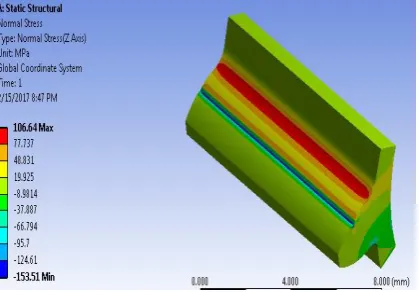
The result shows that deflection value of both trochoidal and circular root fillet gears are similar. But bending stress developed in circular root fillet have less stress (106.64 MPa) compared to trochoidal root fillet gear (122.95 MPa).
[image:3.595.310.522.133.266.2]Deflection of trochoidal and circular root fillet gear is shown in following
Figure- 4. Deflection (trochoidal root fillet)
Figure- 5. Deflection ( circular root fillet )
[image:3.595.311.521.289.435.2]Bending stress of trochoidal and circular root fillet gear is shown in following fig.
Figure- 7. Bending stress (circular root fillet)
If we further analysis is carried out by increasing number of teeth ( 17, 20, 22, 25 ) keeping constant module following result are obtained. These results are compared with modified circular root fillet design.
5.1
COMPARISON OF BENDING STRESS:
For trochoidal root fillet:
N = 17
[image:3.595.37.237.425.542.2] [image:3.595.309.520.570.715.2]© 2017, IRJET | Impact Factor value: 5.181 | ISO 9001:2008 Certified Journal
| Page 2330
N = 20N = 22
N = 25
For circular root fillet:
N = 17
N = 20
N = 22
N = 25
Table-3: Bending stress results :
No. of teeth(N)
Bending stress ( MPa ) % reduction in stress Trochoidal Circular
15 122.95 106.64 13.27
17 117.16 106.75 8.88
20 107.28 103.90 3.15
22 102 99.17 2.77
© 2017, IRJET | Impact Factor value: 5.181 | ISO 9001:2008 Certified Journal
| Page 2331
Graph-1: Graphical representation of bending stress6. CONCLUSION
The effect of proposed circular fillet design on the bending stress induced in spur gear was investigated in comparison with standard trochoidal circular root fillet design. From the results it concludes that deflection in trochoidal and circular root fillet gear tooth is almost same. But there is reduction in bending stress value for circular root fillet design compared to bending stress value in trochoidal root fillet design.
From the results it found that 13.27 % reduction in stress when circular root fillet design is used instead of standard trochoidal root fillet design for existing gear ( 15 no. of teeth ).
From the results it is found that as number of teeth increases % reduction in bending stress decreases. Circular root fillet design is useful for lesser number of teeth and trochoidal root fillet design is suitable for more number of teeth ( more than 22 ).
REFERENCES
1.
V. Spitas, Th. Costopoulos, C. Spitas “ Increasing The Strength of Standard Involute Gear Teeth with Novel CircularRoot Fillet Design”, AJAS, 2005, ISSN : 1546-9239.2.
Kyle Stoker, Anirban Chaudhuri, Nam Ho Kim “ Safety of Spur Gear Design Under Non-Ideal Conditions With Uncertainty”, ASME 2010, IDETC/CIE 2010.3.
S. Sankar, M. Sundar Raj, M. Nataraj “ Profile Modification for Increasing the Tooth Strength in Spur Gear Using CAD “, 2010, ISSN : 740-749.4.
Xiangfei ZHAO, Jie ZHANG, Hongqi LIU “ IncreasingBending Strength in Spur Gear using Shape Optimization of Cutting Tool Profile”, U.P.B.Sci. Bull, Series D, Vol. 76, 2014, ISSN: 1454-2358.