© 2016, IRJET ISO 9001:2008 Certified Journal
Page 440
ANALYTICAL AND NUMERICAL STUDY OF COMPOSITE PLATES
Pallavi kokitakar
1, Prof. C. S. Wadageri
2,Mr. Yogesh Patil
3, Prof. Ratan Patil
41
Student, Dept. of Mechanical Engineering, MMEC Belagavi, Karnataka, India
2
Professor, Dept. of Mechanical Engineering, MMEC Belagavi, Karnataka, India
3
Managing Director of Future technology’s, Belagavi, Karnataka, India
4
Professor, Dept. Of Mechanical Engineering, JGI Belagavi, Karnataka, India
---***---Abstract -
In past few decades considerable workhas been carried out on composites as they are suitable for most of the engineering applications, where specific strength is one of the most important criteria (like automotive and aerospace applications). In this paper the symmetrical and unsymmetrical glass/epoxy, boron/epoxy and graphite/epoxy laminated composite plates are analyzed for different in-plane loading conditions. Thermal loading conditions are also included along with in-plane mechanical loads and the simulations are carried out using ANSYS 14.5 FEA tool. The results are compared with the classical laminate theory (CLT) and it was observed that the results are in unison with each other. Further the mathematical model is generated for CLT by using MATLAB simulation tool for investigating different configurations of composite plate.
Key Words: Finite element analysis (FEA), Classical laminate theory (CLT), Laminate, ply, Composite plate.
1. INTRODUCTION
Composite materials possess enhanced properties compared to other material. Since composite materials have advantages such as light weight, low density, elevated ratio of stiffness and strength, it gives long life to the components. Composite materials wide range of applications in aerospace industry, automotive industry, transport, building and construction, marine & also in medical equipment etc. A laminated composite material consists of some layers of composite combination consisting of matrix and fibers. All layers may have similar or dissimilar material properties with different fiber orientations under varying stacking progression. There are many open issues connecting to design of these laminated composites. Each lamina is represented by the angle of ply and separated from other plies by slash sign. In this work the composite plate are analyzed using both FEA and analytical method considering in-plane loading condition. The study is also extended to understand the combined effect of mechanical and thermal loading on composite plate.
1.1
Classical lamination theory
Relationship between stress, strain and displacement are established for a composite plate under in-plane loads such as shear and axial forces. The classical laminate theory is used to develop these relationships. Some assumptions are made to develop the relationship in the classical lamination theory.
Every lamina is orthotropic. Every lamina is homogeneous.
During deformation the line which is straight and perpendicular to the middle surface remains straight and perpendicular to the middle surface(Mxz = Myz =0)
Every lamina is elastic.
Throughout the laminate displacements are continuous and small. (|p|, |q|, |r|<<|h|), where h is the laminate thickness.
Between the lamina interfaces there is no occurrence of slip.
The thin laminate is loaded only in its plane (Sz=
Nxy = Nyz = 0)
2. Finite element analysis
Finite element analysis has now become integral part of Computer Aided Engineering (CAE) and is been extensively used in the analysis and design of many complex real life systems. It is a numerical method for solving problems of engineering & mathematical physics for complex geometries, materials, loading & boundary conditions.
© 2016, IRJET ISO 9001:2008 Certified Journal
Page 441
Fig-2.1 Orientation & stacking sequence for [0/30/60]In this work 2D rectangular composite plate is used for analysis. The mesh size is 0.5 mm and the thickness of each lamina is 5mm.
[image:2.595.173.547.324.780.2]The materials used for rectangular elements are glass/epoxy, graphite/epoxy and boron/epoxy. Typical mechanical properties for unidirectional lamina are given:
Table -2.1: Mechanical properties of unidirectional lamina
Properties Symbol units Glass/ epoxy
Graphite/ epoxy
Boron/ epoxy
Longitudinal elastic modulus
Y1 GPa 38.6 204 181
Transverse elas2tic modulus
Y2 GPa 8.27 18.50 10.30
Major Poisson’s ratio
V12 0.26 0.23 0.28
Shear
modulus G12 GPa 4.14 5.59 7.17
Longitudinal Coefficient of thermal expansion
α 1 µm/m/0C 8.6 6.1 0.02
Transverse Coefficient of thermal expansion
α 2 µm/m/0C 22.1 30.3 25.5
2.1 Material under loading without temperature
The composite plate is analyzed by using analytical method that is classical laminate theory. The same material for the same fiber orientation is analyzed using MATLAB stimulation tool and it is observed that both the results are in good agreement with each other.
The three ply laminate with orientation of 0/30/-45. The graphite/epoxy material is considered for analysis.
Table -2.1.1: Comparistion between MATLAB and Analytical solution for Graphite/epoxy
Stress in x direction Stress in Y direction Stress in XY direction
MATLAB Analytical
solution MATLAB Analytical solution MATLAB Analytical solution
00 top 33513 33510 61875 61880 -27504 -27500 00
bottom 55767 55770 45312 45310 -12800 -12800
300 69297 69300 73914 73910 33808 33810
top 300
bottom 143360 143400 81022 81020 84256 84260
-450
top
123530 123500 156280 156300 -118670 -118700
-450
bottom -25469 -25470 -18402 -18400 40913 40910
Further the MATLAB results are compared with ANSYS 14.5 analysis tool for different ply orientation of different material.
Glass/Epoxy material is used for the analysis and the ply angle are (0/30/60). The above fig. 2.1 shows the orientation & stacking sequence for [0/30/60] for FEA model.
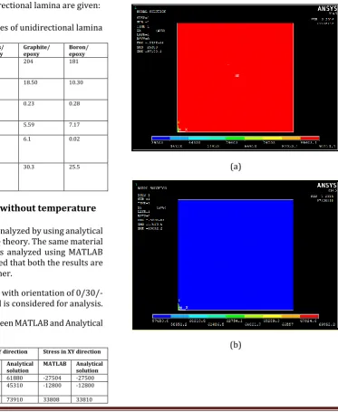
The same materials are simulated using ANSYS 14.5 analysis tool. The contour for stresses is plotted in fig and it observed that both FEA and MATLAB results are in good union with each other.
(a)
[image:2.595.29.293.370.537.2]© 2016, IRJET ISO 9001:2008 Certified Journal
Page 442
(c)Fig-2.1.1: Stress distribution for 00 lamina in (a) X (b) Y
and (c) XY direction
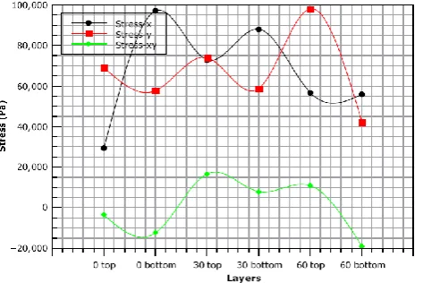
[image:3.595.302.566.200.304.2]Fig-2.1.2 shows the lamina stresses X,Y and XY direction respectivity. These resuls are compared with MATLAB simulation tool as per given in Table no.-2.1.2
Table -2.1.2: Comparistion between MATLAB and ANSYS result for Glass/epoxy.
Stress in x direction Stress in Y direction Stress in XY direction
MATLAB ANSYS MATLAB ANSYS MATLAB ANSYS
00 top 29203 29203 69092 69092.2 -3713.3
-3713.31 00
bottom
97153 97153.1 57684 57683.6 -12496 -12496
300 top 72899 72899.3 73969 73968.8 16639 16639.2
300
bottom 88111 88111.4 58757 58756.7 7856.5 7856.52 600 top 56729 56729.1 98108 98107.6 10843 10842.8
600
bottom
55904 55904.1 42391 42391.1 -19129
-19129.2
The above table shows the result of comparisons of MAT LAB simulation tool and ANSYS analyses tool.
The MATLAB results are given in fig. 2.1.1
Chart -2.1.1: MATLAB results for glass/epoxy composite plate
[image:3.595.30.289.403.527.2]Boron/Epoxy material is used for the anylses and the ply angle are (0/30/60)
Table -2.1.3: Comparistion between MATLAB and ANSYS result for Boron/epoxy.
Stress in x direction Stress in Y direction Stress in XY direction
MATLAB ANSYS MATLAB ANSYS MATLAB ANSYS
00 top -11914 -11914.3 66823 66823 -5977.5 -5977.53
00
bottom 145730 145734 55580 55580.1 -11048 -11047.5 300 top 73443 73442.3 70334 70334.2 12832 12831.9
300
bottom 82224 82224.5 61553 61552.8 7762 7761.95
600 top 68551 68551.2 132760 132763 33514 33514.2 600
bottom 41962 41962 12947 12946.7 -37083 -37083
The above table shows the result of comparisons of MAT LAB situation tool and ANSYS analyses tool.
Graphite/Epoxy material is used for the anylses and the ply angle are (0/30/60)
Table -2.1.4: comparistion between MATLAB and ANSYS result for Graphite/epoxy
Stress in x direction Stress in Y direction Stress in XY direction
MATLAB ANSYS MATLAB ANSYS MATLAB ANSYS
00 top -64138 -64137.9 61791 61791 -11180 -11180
00
bottom 188490 188491 51273 51272.6 -22870 -22870.3 300 top 84501 84500.6 78083 78082.8 28939 28938.6
300
bottom 104750 104749 57835 57834.6 17248 17248.3
600 top 65771 65770.9 173990 173993 47982 47982.1
600
bottom
20627 20626.7 -22974 -22973.5 -60119 -60118.8
The above table shows the result of comparisons of MAT LAB situation tool and ANSYS analyses tool. Now as it is established that results obtain from both MATLAB coding and ANSYS simulation have sink with the analytical results.
[image:3.595.302.565.423.531.2] [image:3.595.40.277.599.757.2]© 2016, IRJET ISO 9001:2008 Certified Journal
Page 443
Fig-2.1.2: Orientation & stacking sequence for[30/60/30/60]
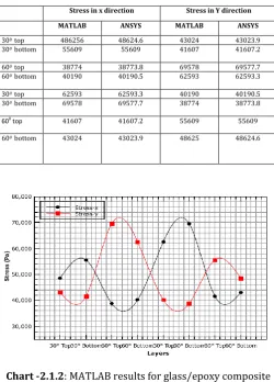
Fig-2.1.3 shows the lamina stresses X and Y direction respectivity. These resuls are compared with MATLAB simulation tool as per given in Table no.-2.1.5
The table-2.1.5 shows the result of comparisons of MAT LAB situation tool and ANSYS analyses tool
.
(a)
[image:4.595.34.288.98.255.2](b)
Fig-2.1.3: Stress distribution for 00 lamina in (a) X
(b) Y direction
Table -2.1.5: comparistion between MATLAB and ANSYS result for Glass/epoxy
Stress in x direction Stress in Y direction
MATLAB ANSYS MATLAB ANSYS
300 top 486256 48624.6 43024 43023.9
300 bottom 55609 55609 41607 41607.2
600 top 38774 38773.8 69578 69577.7
600 bottom 40190 40190.5 62593 62593.3
300 top 62593 62593.3 40190 40190.5
300 bottom 69578 69577.7 38774 38773.8
600
top 41607 41607.2 55609 55609
600 bottom 43024 43023.9 48625 48624.6
[image:4.595.307.558.375.724.2] [image:4.595.34.561.383.763.2]© 2016, IRJET ISO 9001:2008 Certified Journal
Page 444
Now as it is established that results obtain fromboth MATLAB coding and ANSYS simulation have sink with the analytical results.
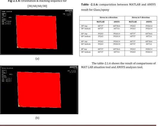
[image:5.595.306.574.97.278.2]Glass/Epoxy material is used for the analysis and the ply angle are (30/60/60/30). The above fig. 2.1.1 shows the orientation & stacking sequence for [30/60/60/30] for FEA model.
Fig-2.1.4: Orientation & stacking sequence for [30/60/60/30]
(a)
(b)
(c)
Fig-2.1.5: Stress distribution for 00 lamina in (a) X (b) Y
[image:5.595.38.287.202.343.2]and (c) XY direction
Fig 2.1.5 shows the lamina stresses X and Y direction respectivity. These resuls are compared with MATLAB simulation tool as per given in Table no.-2.1.6
Table -2.1.6: comparistion between MATLAB and ANSYS result for Glass/epoxy
Stress in x direction Stress in Y direction
MATLAB ANSYS MATLAB ANSYS
300 top 60737 60736.6 39263 39263.4
300 bottom 60737 6073.6 39263 39263.4
600 top 39263 39263.4 60737 60736.6
600 bottom 39263 39263.4 60737 6073.6
600 top 39263 39263.4 60737 60736.6
600 bottom 39263 39263.4 60737 6073.6
300
top 60737 60736.6 39263 39263.4
300 bottom 60737 6073.6 39263 39263.4
[image:5.595.36.567.357.778.2]© 2016, IRJET ISO 9001:2008 Certified Journal
Page 445
Chart -2.1.3: MATLAB results for glass/epoxy compositeplate
Now as it is established that results obtain from both MATLAB coding and ANSYS simulation have sink with the analytical results.
3. CONCLUSIONS
The composite plates are analysed considering different process parameters like fiber orientation, stacking sequence and boundary conditions. The simulations were also carried out on different materials like glass/epoxy, graphite/epoxy and boron epoxy composites. Both symmetric and unsymmetrical composite plates were analyzed using mechanical conditions with the help of ANSYS simulation tool. The results obtained by classical laminate theory were compared with the results obtained from hand calculation and they are in unison with each other. The classical laminate model was also established using MATLAB simulation tool and the results were in good agreement with FEA results obtained from ANSYS.