http://www.sciencepublishinggroup.com/j/ijssn doi: 10.11648/j.ijssn.s.2017050501.11
Conference Paper
Implementation of Fuzzy Logic Controller (FLC) for DC-DC
Boost Converter Using Matlab/Simulink
Kaoutar Bendaoud, Salahddine Krit, Mustapha Kabrane, Hassan Ouadani, Mohamed Elaskri,
Khaoula Karimi, Hicham Elbousty, Lahoucine Elmaimouni
Laboratory of Engineering Sciences and Energies, Polydisciplinary Faculty of Ouarzazate, IbnZohr University, Agadir, Morocco
Email address:
[email protected] (K. Bendaoud), [email protected] (S. Krit), [email protected] (L. Elmaimouni)
To cite this article:
Kaoutar Bendaoud, Salahddine Krit, Mustapha Kabrane, Hassan Ouadani, Mohamed Elaskri, Khaoula Karimi, Hicham Elbousty, Lahoucine Elmaimouni. Implementation of Fuzzy Logic Controller (FLC) for DC-DC Boost Converter Using Matlab/Simulink.International Journal of Sensors and Sensor Networks. Special Issue: Smart Cities Using a Wireless Sensor Networks. Vol. 5, No. 5-1, 2017, pp. 1-5.
doi: 10.11648/j.ijssn.s.2017050501.11
Received: March 21, 2017; Accepted: March 27, 2017; Published: April 15, 2017
Abstract:
Nowadays, DC-DC converters circuits are widely used in electronics systems in order to obtain a stabilized output voltage from a given input DC Voltage. Performance of DC-DC converters is dependent on the choice of control methods. Consequently, controlling of DC-DC converter represents essential task in power conversion.The research problem addressed in this paper is to model a controlling system for Boost DC-DC converter. In this way a logic fuzzy controller is used and simulated using MATLAB/SIMULINK to increase converter efficiency and power efficiency.Keywords:
DC/DC Boostconverter, Fuzzy Logic Controller, Matlab/Simulink, Controlled Converter1. Introduction
DC-DC converters are nonlinear system in nature due to their switching property. Static and dynamic characteristics of these converters have been widely discussed in the literature. In many industrial applications there is a need for the transformation of a constant dc voltage source to a variable dc voltage source, and like a transformer, the converter can be employed for stepwise increase or reduction of dc source voltage [1]. In this way, Boost converter is a dc-dc converter in which the output voltage is always greater than the input voltage which depends on switching frequency [2]. Output voltage regulation in the dc-dc converter is achieved by constantly adjusting the amount of energy absorbed from the source and that injected into the load, which is in turn controlled by the relative durations of the absorption and injection intervals. These two basic processes of energy absorption and injection constitute a switching cycle [3]. In this context,Many control methods are used for control of switch mode DC-DC converters and the simple and low cost controller structure is always in demand for most industrial and high performance applications [4]. Several control strategies and mathematical models have been developed by
2. DC-DC Boost Converter Circuit Model
In many industrial applications, it is required to convert a fixed-voltage DC source into a variable voltage DC source. A DC –DC converter converts directly from DC to DC and is
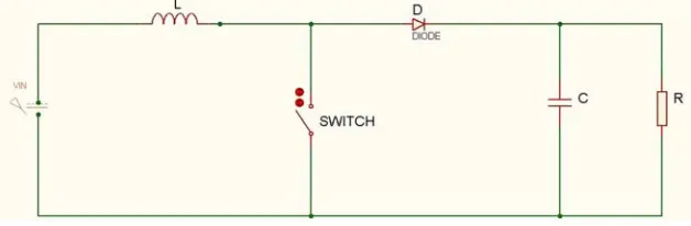
simply known as a DC converter. A boost converter provides an output voltage greater than the input voltage. The circuit arrangement of a boost converter is shown in figure 1; it consists of four essential components: Inductor, switch, diode and output capacitor.
Figure 1. Basic configuration of boost converter.
Boost converter can operate into two modes. The first mode starts when switch is on at t=0.The input current rises and flows through inductor and switch while second mode begins at t = to n ,the input current flows through inductor,capacitor, and diode, the inductor current falls until next cycle and energy stored in inductor flows through load.
In steady state time integral of the inductor voltage over one time period must be equal to zero as shown in equation 1
* ( ) * 0
IN on IN OUT off
V t + V −V t = (1)
Where:
IN
V : Input voltage
OUT
V : Average output voltage
on
t : Switching on time
off
t : Switching off time
Dividing both sides by TSand rearranging terms we obtain:
1 1
OUT S
IN off
V T
V =t = −D (2)
Where:
S
T : Switching cycle D: Duty cycle
When switch turns on, current is passing through switch. Consequently, current increases in the inductor.When switch turns off, current stored into inductor is IL,So:
L IN
di
V L
dt
= (3)
Applying Laplace transformation to equation (3) we obtain:
( ) * * ( )
IN L
V s =L s I s (4)
On other hand:
* ( )
OUT L
V =R I s (5)
From equation (4) we obtain:
*
OUT
IN
V R
V =L s (6)
Which represents transfer function of boost converter.
3. Fuzzy Logic Controller
Fuzzy controllers fulfill the same tasks like a classic controller. Fuzzy controller differs from the classic one in that it manages the control complex space in a heuristic manner. However, the fuzzy controller can approximate, with any precision level, linear and non-linear control functions. In many situations is easier to obtain a fuzzy controller with high performance than a classic controller with same performances [7]. The most important specifications of fuzzy control method are their fuzzy logical ability in the quality perception of system dynamics and the application of these quality ideas simultaneously for power systems [8].
Four major units are fuzzification block, a fuzzy knowledge-base block, a fuzzy inference engine and a defuzzification block [9] as shown in Figure 2.
The functions of the blocks of the fuzzy system are briefly summarized in below:
The fuzzier interface is a block which classify input datainto suitable linguistic values or sets ; it measures values of input variables in order to convert them into suitable values that may be viewed as labels of fuzzy. The knowledge base is comprised of two components namely called fuzzy sets (data base) and fuzzy control rule base. The concepts associated with fuzzy sets are used to characterize fuzzy control rules and fuzzy data manipulation in an FLC. These concepts are subjectively defined and based on experience. So, it should be noted that the correct choice of the membership functions of a term set plays an essential role in the success of an application [10]. While fuzzy decision maker represents the kernel of a fuzzy logic controller, it has capability of simulating human decisionmaking based on fuzzy concepts and of inferring fuzzy control actions using fuzzy implication (fuzzy relation) and the rules of inference in fuzzy logic. This means that the
fuzzy decision maker handles rule inference where human experience can easily be injected through linguistic rules. Finally, defuzzier interface converts the conclusion from the fuzzy logical decision maker into the control input to the plant.
4. Modeling of Fuzzy Logic Controller for
BOOST Converter Using
Matlab/Simulink
The intend of this part is to model DC-DC boost converter and fuzzy logic controller (FLC) which improve efficiency and performance of the converter. Modelling and simulation are performed on Matlab/Simulink.
A. Boost converter modeling using Matlab/Simulink
Referring to the equation (6), the boost converter can be modelled as a transfer function to permit automatic tuningas shown in Figure 3.
Figure 3.Transfer function model of boost converter.
B. Fuzzy logic controller modeling using Matlab/Simulink
The boost dc-dc converter is a nonlinear function of the duty cycle because of the small signal model and its control method was applied to the control of boost converters. Fuzzy controllers do not require an exact mathematical model. Instead, they are designed based on general knowledge of the plant. Fuzzy controllers are designed to adapt to varying
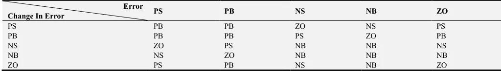
operating points. Fuzzy Logic Controller is designed to control the output of boost dc-dc converter using Mamdani style fuzzy inference system. Two input variables, error (e) and change of error (de) are used in this fuzzy logic system. The single output variable (u) is duty cycle of PWM output.[11] Then, it is necessary to determine membership functions assigned to inputs and outputs as shown in Table 1.
Table 1. Fuzzy control rules.
Error
Change In Error PS PB NS NB ZO
PS PB PB ZO NS PS
PB PB PB PS ZO PB
NS ZO PS NB NB NS
NB NS ZO NB NB NB
ZO PS PB NS NB ZO
The role of fruzzy logic controller is to control the output voltage of the boost converter.Fuzzy logic controller has two inputs which are error and change in error. These inputs are divided into five groups;(NB) Negative Big,(NS) Negative Small, (PS) Positive Small, (PB) Positive Big, (ZO) Zero Area, as shown in Table-1.
5. Simulation Results
Figure 4. Simulink model of boost converter with fuzzy logic controller.
A simulation run for the Boost Converter is carried out whose design parameters are specified in Table 2.
Table 2. Design parameters.
Parameters Values
Input voltage 5 V
Output voltage 12 V
Load resistance 500Ω
Frequence 50 KHZ
Inductance 200 µH
Capacitance 200µF
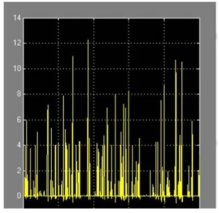
Waveforms of boostconverter output voltage in open loop mode are shown in Figure 5.
Figure 5. Output voltage in open loop mode.
The simulation results of output voltage for boost converter with fuzzy logic controller are shown in following figures, the value of output voltage is getting about 12V. Figure 6 and Figure 7show results of fuzzy controlled boostconverter for supply voltage 12V and load variant conditions. Figure 8 and Figure 9 show results for 500 ohm load and input supply variant voltage.
Figure 6. Output voltage of fuzzy controlled buckConverter for 5 ohm load.
Figure 7. Output voltage of fuzzy controlled buckConverter for 500 ohm load.
Figure 8. Output voltage of fuzzy controlled buck converter for 5V supply voltage.
In open loop mode, output voltage is sensitive to parameters variations (Figure 5). Results of fuzzy controlled boost converter for 5V supply voltage and load variant conditions show that output voltage is 12.8 V for 5 Ohm load (Figure 6) and is 11.5 V for 500 Ohm load (Figure 7).While results of fuzzy controlled buck converter for 500 Ohm load and variant supply voltage show 12.3V for 5 V supply voltage (Figure 8) and 11.8V for 20V supply voltage (Figure 9).
6. Conclusion
In this paper, we provided a brief overview of DC-DC boost converter and fuzzy logic controller, and proceeded to illustrate a model of fuzzy logic controlled boost converter using Matlab/Simulink. This paper demonstrated the effectiveness of fuzzy controller applied to DC-DC boost converter. Good behavior of the boost converter proves the robustness of the controller especially it shows good stabilization quality.
Acknowledgment
Kaoutar Bendaoud & all aregratefully acknowledges the support by the National Centre for Scientific and Technical Research (CNRST) of Morroco.
References
[1] M. BAYATI POODEH, S. ESHTEHARDIHA, M. R. ZARE, “Application of Fuzzy Logic to Control the DC-DC Converter”, 7th WSEAS International Conference on Electric Power Systems, High Voltages, Electric Machines, Venice, Italy, November 21-23, 2007.
[2] K. B. Khanchandani, and M. D.Singh, Power Electronics, New Delhi:Tata Mcgrawhill, 2005.
[3] Mohammed, B. M Hasaneen, and Adel A. Elbaset. "Design and Simulation of DC-DC Boost Converter," 2008.
[4] Tobias Geyer, GeorgiosPapafotiou and Manfred Morari, Constrained Optimal Control of the Step-Down DC–DC Converter IEEE Transactions on Power Electronics, Vol. 23, No. 5, September 2008.
[5] Ned Mohan, W. P. Robbins and T. M. Undeland, R. Nilssen and Olive Mo: Simulation of Power Electronic and Motion Control System Proceedings of the IEEE, Vol.82, No.8, August 1994, pp. 1287–1292.
[6] Paolo Mattavelli, L. R., Giorgio Spiazzi and Paolo Tenti, 1997. General-Purpose Fuzzy Controller for DC-DC converters IEEE Trans, 12(1): 79-86.
[7] Eremia M., Cartina G., Petrica D., s. a. Artificial intelligence techniques in the management of power systems. EdituraAgir, Bucuresti, 2006.
[8] Terano, T., AsaI, K., Sugeno, M.,applied fuzzy systems, Academic Presss Inc., pp.86-93, 1994.
[9] Lee, C. C., Fuzzy Logic in Control Systems :Fuzzy logic controller Part I, IEEE Trans. On Syst. Man Cybern., vol. 20. [10] K. V. H. Prasad, CH. U. M. Rao, A. S. Hari, “Design and
simulation of a fuzzy Logic Controller for Buck & Boost Converters”, nternational Journal of Advanced Technology & Engineering Research, May 2012,Vol. 2, Issue3, pp. 218-224. [11] Ganji Sai Kumar, G. Ramudu, D. Vijay Arun, “Analysis and