© 2017, IRJET | Impact Factor value: 5.181 | ISO 9001:2008 Certified Journal | Page 1041
A Time Sharing Scheme for Room Ventilation Control using a Smart
Sensing Actuator
R.Raja Prabhu
1, R.Sreevidya
21
Assistant Professor, Dept of Electrical and Electronics Engineering, Imayam College of Engineering, Trichy,
Tamilnadu, India, [email protected]
2
Assistant Professor, Dept of Electrical and Electronics Engineering, TRP Engineering College, Trichy,
Tamilnadu, India, [email protected]
---***---Abstract -
This paper proposes a system that acts as a mechanism for room ventilation control in a time-sharing manner by using a self sensing actuator. The ventilation fan alone cannot be used as the actuator and sensor. It can be used in a time sharing manner. Generally the motors and actuators contain internal feedback. The motors function as a generators, and actuators generate normally a force is applied to them. This implies a reversible process mechanism. The function of a ventilation fan was obtained by analyzing the automatic control by using the ventilation system in the sealed house. The change in pressure in between the inner and outer portion of the room due to exhaust, the high sensing actuator will act as a power generator from which the motor generates a voltage. The main power scheme was mentioned below: when the voltage from the sensing fan, which is at a standstill, exceeds a threshold value, the ventilation fan starts rotating for a short period of time and comes to idle position mode to observe the pressure. These processes are repeated again and again. A ventilation fan with the area of 0.25 m acts as a high sensitive gauge pressure sensor at pressure up to 3.0 Pa, with the frequency range of 0.2 Hz. The controller which turns the ventilation fan on when the pressure exceeds 3.5 Pa for 12 s and returns it to standstill mode worked well in an actual airtight room.Key Words
:
Actuator, Time sharing, sensitive pressure sensor, Ventilation fan, Reversible Process.
1. INTRODUCTION
The ventilation of houses is important to keep a house in good condition and maintain the health of its occupants. In most old houses, the air is ventilated by exhaust fans because there are so many no of aeration holes along through which external air penetrates. By contrast, newly built houses are airtight to keep out external noise and for energy efficiency. For reasonable ventilation, there should be a good balance between aeration and exhaust, but the most no of houses have active aeration fans or passive holes for exhausting air, which causes a new problem. Sometimes an exhaust fan is
placed in another room where the doors are closed, or someone closes the hole to stop hot or cold air from entering. In such cases, the pressure in the house may fall by 10 Pa, and the door may be difficult to open owing to the negative pressure. In addition, because of the poor aeration owing to the negative pressure, the air is not ventilated even if the aeration fan works properly. Most people believe that the room is ventilated if they hear the sound of the aeration fan; however, this may not be the case. At worst, this could cause carbon monoxide poisoning. The kitchens of newly built buildings have both an aeration fan and an exhaust fan, some of which work simultaneously but most of which are independent, because if a kitchen window is open, the exhaust fan does not need to be on. Similarly, ventilation in many kitchens in restaurants is dangerous or ineffective.
This paper describes a solution to these problems. The basic strategy is an automatic feedback control for ventilation. We measure the pressure difference between the inside and outside of the house. The pressure inside the house decreases, when the exhaust fan works, then only the ventilation is not sufficient when the windows or ventilation holes are closed or the ventilation fan is at a standstill. Usually, we manually turn on the ventilation fan; thus, an ON-OFF ventilation control is sufficient. Two problems in creating a feedback system are pressure measurement and cost. In our application, a pressure on the order of several Pa with very low frequency must be measured, but there are no suitable low-cost and highly sensitive sensors.
© 2017, IRJET | Impact Factor value: 5.181 | ISO 9001:2008 Certified Journal | Page 1042
2. LITERATURE SURVEY
This paper presents the use of the actuators as sensors has been studied in the fields of self-sensing actuation, sensor less actuation, and shared sensing for reversible devices [1]– [9]. As electromagnetically actuated systems, the vehicle suspension system, vibration isolation platforms, and the control of enclosed-sound fields were considered as potential applications [1]. A speed-sensor less AC drive control system for an induction motor [2], a positioning system for a sensor less linear DC motor [3], and a speed-sensor less direct torque control for an induction motor [4] have been investigated. There are also many research studies that use piezoelectric devices as self-sensing actuators [5]–[9]. The main advantages of the self-sensing scheme are 1) the embed ability of the measurement technique and 2) its low cost, as no additional sensor is required [9]. In addition, ventilation and air conditioning account for a large percentage of power consumption [10]– [12] and have been developed energy-saving heating, ventilation, and air conditioning (HVAC) systems [13]–[16].
The proposed method here is a self-sensing actuation technique but is newly applied to a practical ventilation problem to verify that the ventilation fan functions as a highly sensitive pressure sensor. We will verify the feasibility of the proposed ventilation system in a real kitchen.
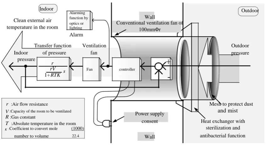
Fig -1: General ventilation feedback control system
3. SYSTEMS
[image:2.595.87.511.483.715.2]Figure 1 shows a general conceptual ventilation feedback control system. The pressure difference between the inside and outside of the room is measured by a sensitive gauge pressure sensor. Based on the measured pressure difference, the controller generates a signal to reduce the difference, and the ventilation fan feeds external air to the room, with characteristics given by a first-order transfer function in Fig. 1.
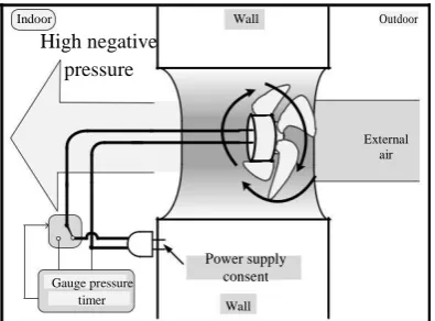
Figure 2 shows the proposed ventilation feedback control system in which a ventilation fan is used as an actuator as well as a highly sensitive gauge pressure sensor in a time-sharing manner. Fig. 3 shows the ventilation fan in standstill mode with no electric power supplied. When the pressure difference between the inside and outside of the fan exceeds a certain range, the fan begins to rotate by overcoming the friction force of the shaft of the fan, and the basket-type induction motor generates AC voltage. In this type of motor, there is no magnet but there is iron, which is a magnetic substance, to support the basket. The iron support is slightly magnetized. If strong magnets were used, they would pull the rotor strongly and cogging would occur, impeding rotation by external force. In the basket type of induction motor, the cogging force is weak and the motor easily rotates, generating a low AC voltage.
Indoor
Alarming Outdoor
Wall
Clean external air function by optics or Conventional ventilation fan of
temperature in the room lighting 100mmΦr
Alarm
Transfer function Ventilation Outdoor
Indoor of pressure fan pressure
pressure
r
+
1+
rV s Fan controller
RTK
-
r :Air flow resistance
Mesh to protect dust
V :Capacity of the room to be ventilated
Power supply and mist
R :Gas constant
consent Heat exchanger with
T :Absolute temperature in the room
sterilization and K :Coefficient to convert mole (1000)
© 2017, IRJET | Impact Factor value: 5.181 | ISO 9001:2008 Certified Journal | Page 1043 In this case, we use the induction motor not as a generator
to produce high power but as a sensor to provide a signal with low power. Thus, the fan can be rotated with a weak external force or small pressure difference. If the output voltage of the motor corresponds to the pressure difference at which ventilation is required, the controller switches to supply power to the fan, as shown in Fig. 3, and external air is taken in; this condition continues for a certain period and then returns to standstill mode to monitor the pressure difference. This system is automatic. In the exhaust period, if any window or exhaust hole is fully open, the pressure may not decrease and ventilation may not be carried out by the system. If for some reason all of the windows, doors, and holes are closed, the pressure decreases and ventilation is required, and the system carries out ventilation. Thus, the system works when required.
Fig -2: Feedback system using a fine gauge pressure sensor
Fig -3: Feedback system using ventilation fan as a pressure sensor
[image:3.595.346.507.187.311.2]4. EXPERIMENTS
Figure 4 shows the ventilation fan used, and Table I shows the specifications. This is the smallest type of ventilation fan available.
4.1 Characteristics as a Gauge Pressure Sensor
Figure 4 shows the experimental setup used to investigate the characteristics. The calibrated manometer detects pressures in the range of 0.0001 Pa to 20 Pa with a cut-off frequency of 10 Hz.
Fig -4: Ventilation fan used in the experiment
Table -1: Specification of Ventilation Fan
Model number V-06PC5
Power 1.5 W
Air flow 85 m3/h
Noise 15 dB
Weight 0.45 kg
Voltage of power AC 110 V
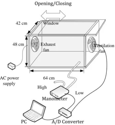
The exhaust fan, which is the same as that for ventilation shown in Fig. 5, was installed at one side of an air-sealed box of volume 0.125 m3 with a window. Another ventilation fan
was installed on the other side as the aeration fan. When the exhaust fan is working, the pressure in the box decreases. The negative pressure in the box is adjusted by opening or closing the window, and the pressure is measured by the manometer. The output voltages from the manometer and aeration fan are recorded on a personal computer through an A/D converter.
Figure 5 shows the output pressure and AC voltage output measured in a step-response manner just after switching on the exhaust fan. The output of the exhaust fan is delayed compared with the output of the manometer. The time constant of the manometer was 0.9 s, and that of the ventilation fan was 1.6 s. This is because of the time delay for the revolution force of the fan to become greater than the friction force. The cut-off frequency of the ventilation fan gauge pressure sensor is 0.1 Hz, which is insensitive to sudden pressure changes such as the opening or closing of a door.
Indoor Wall Outdoor
Low negative Conventional aeration fan of 100mmΦ pressure
Motor
Fan
External air
Power supply consent
Gauge pressure
timer Wall
Indoor Wall Outdoor
High negative pressure
External air
Power supply
Gauge pressure consent
[image:3.595.66.264.305.452.2] [image:3.595.349.517.369.454.2] [image:3.595.66.264.495.641.2]© 2017, IRJET | Impact Factor value: 5.181 | ISO 9001:2008 Certified Journal | Page 1044 Opening/Closing
Manometer
PC A/D Converter
Fig -5: Experimental Setup
Chart 1 shows the pressure vs. voltage characteristics. The ventilation fan works as a frequency-type gauge pressure sensor and its output is obtained in the form of frequency. Chart 2 shows the pressure vs. frequency characteristics. Both outputs show a linear relationship with pressure. As shown in Fig. 5, the fan begins to rotate at a pressure of 2.0 Pa; thus, a pressure less than 2.0 Pa cannot be measured. The linear regression of the plots is shown in Chart. 1 and Chart. 2 are calculated and expressed as flows:
v = 0.04 p - 0.001 with R2= 0.98 for p > 2 Pa
f = 1.1p + 0.75with R2 = 0.97 for p > 2 Pa
Thus, the pressure is measured by the amplitude or frequency of the voltage of the aeration fan as follows:
p = 25 v + 0.025 for v > 0.05V
p = 0.91 f - 0.68 for f > 3 2.Hz
Chart -1: AC Voltage Vs Pressure
Chart -2: Frequency Vs Pressure
This pressure is very low, since most sensitive industrial gauge pressure sensors require a minimum pressure of around 3 Pa, which is higher than that of our ventilation-fan type of sensor.
[image:4.595.39.263.99.343.2]4.2 Automatic Ventilation System
Figure 6 shows a flowchart of the control sequence. When the fan is at a standstill, it is disconnected from the AC power supply, is in windmill mode, and monitors the pressure proportional to the voltage generated by the induction motor.
Fig -6: Flow chart of the control sequence 42 cm Window
48 cm Exhaust Ventilation
fan fan
AC power 64 cm
supply
High
Low
Start Monitoring
indoor pressure
NO
Indoor pressure below
3.5 Pa YES Ventilation for 12 seconds
Fan is at stand still
[image:4.595.309.492.115.229.2] [image:4.595.32.230.582.748.2]© 2017, IRJET | Impact Factor value: 5.181 | ISO 9001:2008 Certified Journal | Page 1045 Once the voltage exceeds 0.12 V, which corresponds to a
pressure of 3 Pa, the circuit switches on, connecting the terminal to the AC power supply and performing aeration for 10 s, and then returns to standstill mode to monitor the pressure.
6.1 m
2.2 m
A
B
3.8 m
2.9 m
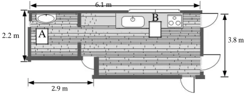
Fig -7: A kitchen of 43.5 m3 volume with 810 m3/h
exhaust fan in the range hood.
5. EXPERIMENTS RESULTS
The performance of the automatic ventilation sequences shown in Fig. 7 was examined. The experiments were carried out under an experimental setup as well as in an actual kitchen. When a window is opened, the pressure returns to atmospheric pressure, and the exhaust fan remains at a standstill. Figure 7 shows the floor plan of the actual kitchen where there was an 810-m3/h exhaust fan in the range hood.
At the maximum exhaust setting, the pressure decreased to -9.0 Pa.
We set the ventilation fan in Fig. 4 with an air flow of 85m3/h, which is the same as shown in Fig. 4 as the control
ventilation fan. The solid curve shows the case when the exhaust fan is on and no control is applied. The pressure decreases -3.0 Pa from atmospheric pressure and remains low. The dotted curve shows the pressure when the controller works, and every other 10 s it exhausts air and increases the pressure from -3.0 Pa to -1.2 to -1.5 Pa. Because the capacity of the ventilation control fan is a tenth less than that of the exhaust fan, the pressure cannot reach 0.0 Pa, but the controller worked well in the actual kitchen.
From the experimental results, the proposed system worked. In an automatic manner without manually switching on the ventilation fan or opening a window when exhausting Furthermore, in comparison with the new type of ventilation system in which room air is exhausted and aerated simultaneously even if aeration is not necessary, the proposed system works when it is necessary, which prevents wasteful consumption of energy.
CONCLUSION
This paper described a time-sharing control scheme by using an actuator as a sensor for automatic room ventilation control when a ventilation fan was used both for ventilation and as a highly sensitive low-frequency
pressure sensor for ON-OFF feedback control. The control system requires only a simple switching circuit to switch on the power supply when the AC voltage generated by the induction motor in the fan acting as a windmill exceeds a specified threshold value. The circuit can be installed in a power supply casing. The ventilation fan is highly sensitive as a pressure sensor with low-pass filtering. The minimum pressure detectable by the fan was 3.0 Pa, and the cut-off frequency was 0.2 Hz. These values are sufficiently sensitive in gain for the fan to be used as a pressure sensor to detect negative pressure in an airtight room owing to exhaustion, and to reduce the negative gauge pressure. They are sufficiently low in cut-off frequency not to be sensitive to rapid changes in pressure caused by a door opening and closing.
The proposed ventilation system provided the automatic self-sensor-based aeration control that measures the fine pressure decrease in the room using the aeration fan itself. The system makes persons free from switching on the aeration fan or opening a window when exhausting air. Furthermore, it works when it is necessary, whereas the conventional new type of ventilation systems exhaust and aerate simultaneously even if the aeration is not necessary, which wastes energy.
REFERENCES
[1] A. J. Fleming, S. O. R. Moheimani, and S. Behrens, “Synthesis and Implementation of Sensor-Less Active Shunt Controllers for Electromagnetically Actuated Systems,” IEEE Trans. on Control Systems Technology, Vol. 13, No. 2, 2005, pp. 246–261
[2] W. Chagjiang, T. Guojun, and W. Nanyan, “High Performance Speed-Sensor-Less AC Drive System for Induction Motor,” IEEETENCON ‘93/Beijng 1993, pp. 602– 606
[3] M. Norhisam, H. Ezril, M. Senan, N. Mariun, H. Wakiwaka, and M. Nirei,“Positioning System for Sensor less Linear DC Motor,” First International Power and Energy Conference PECON 2006 November 28–29, Putrajaya, Malaysia, 2006 [4] Y. Sayouti, A. Abbou, M. Akherraz, and H. Mshoudi, “Sensor less Low Speed Control With ANN MRAS For Direct Torque Controlled Induction Motor Drive,” Proceedings of the 2011 International Conference on Power Engineering, Energy and Electrical Drives, Torremolinos (Málaga), Spain, May 2011
[5] C. K. Pang, G. Guo, B. M. Chen, and T. H. Lee, “Self-Sensing Actuation for Nan positioning and Active-Mode Damping in Dual-Stage HDDs,” IEEE/ASME Trans. on Mechatronics, Vol. 11, No. 3, 2006, pp. 328–338
[image:5.595.43.286.169.269.2]© 2017, IRJET | Impact Factor value: 5.181 | ISO 9001:2008 Certified Journal | Page 1046 [7] T. Das and R. Mukherjee, “Shared-Sensing and Control
Using Reversible Transducers,” IEEE Trans. on Control Systems Technology, Vol.17, No. 1, 2009, pp. 242–248 [8] A. Badel, J. Qiu, and T. Nakano, “Self-Sensing Force Control of a Piezoelectric Actuator,” IEEE Trans. on Ultrasonic’s, Ferroelectrics, and Frequency Control, Vol. 55, No. 12, 2008, pp. 2571–2581
[9] M. Rakotondrabe, I. A. Ivan, S. Khadraoui, P. Lutz, and N. Chaillet, “Simultaneous Displacement/Force Self-Sensing in Piezoelectric Actuators and Applications to Robust Control,” IEEE/ASME Trans. on Mechatronics,Vol. 20, No. 2, 2015, pp. 519–531
[10] M. A. Cleveland, and J. M. Schuh, “Automating the Residential Thermostat Based on House Occupancy,” Systems and Information Engineering Design Symposium (SIEDS), IEEE 2010, pp. 36–41
[11] T. Nakahama D. Biswas, K. Kawano, and F. Ishibashi, “Improved Cooling Performance of Large Motors Using Fans,” IEEE Trans. On Energy Conversion, Vol. 21, No. 2, 2006, pp. 324–331
[12] S. Kar, and P. K. Varshney, ” Accurate Estimation of Gaseous Strength Using Transient Data,” IEEE Trans. on Instrumentation and Measurement, Vol. 60, No. 4, 2011, pp. 1197–1205
[13] Cleveland M. A. and J. M. Schuh, “Automating the Residential Thermostat Based on House Occupancy,” Proceedings of the 2010 IEEE Systems and Information Engineering Design Symposium, University of Virginia, Charlottesville, VA, USA, April 23, 2010.
[14] M. Vasak, A. Starcic and A., Martincevic., “Model Predictive Control of Heating and Cooling in a Family House,” MIPRO 2011, May 23–27, 2011, Opatija, Croatia.
[15] B. Sun, P. B. Luh, Q. Jia, Ziyan Jiang, F. Wang, and C. Song, “Building Energy Management: Integrated Control of Active and Passive Heating, Cooling, Lighting, Shading, and Ventilation Systems,” IEEE Trans. On Automation Science and Engineering, Vol. 10, No. 3, 2013, pp. 588–602.
BIOGRAPHIES
R.Raja Prabhu received the B.Eng (I) in Electrical and Electronics Engineering from Anna University, Chennai in 2005. He completed the M.Eng (I) in Applied Electronics from Anna University, Coimbatore in the year 2009. He is now working as assistant professor in the department of electrical and electronics engineering in Imayam College of Engineering, Trichy, India.
His area of interest includes power electronic converters, power factor correction, energy conversion and renewable energy applications.
R.Sreevidya was born in the state of tamilnadu, India. She received the BE degree in Electrical and Electronics Engineering from Anna University, Chennai in 2010 and ME degree in Power Electronics and Drives from Anna university, Chennai in 2014. She is now working as assistant professor in the department of electrical and electronics engineering in TRP Engineering College, Trichy, India.