© 2017, IRJET | Impact Factor value: 5.181 | ISO 9001:2008 Certified Journal
| Page 1581
A Sphere Decoding Algorithm for MIMO
Jay D Thakar
Electronics and Communication
Dr. S & S.S Gandhy Government Engg College
Surat, INDIA
---***---
Abstract -
Modern wireless communication systemdemanding high data rate operating in bandwidth deficient world is using Multiple Input Multiple Output (MIMO) antenna arrangement. MIMO transmission has become a popular technique to increase spectral efficiency. MIMO supports greater data rate and higher reliability in wireless communication. The receivers employing linear receivers or decision feedback detectors in detection use less hardware are of suboptimal. Optimal detectors are realized by Maximum Likelihood detector can achieve superb performance, yet the computational complexity is enormously high. Therefore suboptimal detectors such as Viterbi Decoding, Sphere Decoding, Genetic Algorithm based Decoder are reach the performance of ML detectors, and potentially a great deal of computational cost can be saved. In this paper, a practical sphere-Decoding algorithm is proposed. It utilizes a simple and effective way to set the initial radius which plays a decisive role in determining the computational complexity. The complexity and SER rate of the sphere decoder is good when compare with other decoders used in MIMO receiver design. The performance of sphere decoder and maximum likelihood decoder is same but the complexity is reduced in sphere decoder.
Key Words: Muliple-Input-Muliple-Output (MIMO) system, decoders, sphere decoder, maximum likelihood, complexity.
1.INTRODUCTION
Wireless system engineers are encountering a number of challenges. These include the limited availability of radio frequency spectrum, Power, and a time varying wireless environment. In addition, there is an increasing demand for higher data rates, better quality of service, and higher network capacity. Over the past decade, Multiple-Input Multiple-Output (MIMO) systems have evolved as a most promising technology in these measures.
Multiple-Input Multiple-Output (MIMO) wireless antenna systems have been recognized as a key technology for future wireless communications. To achieve the capacity of MIMO systems is to use spatial multiplexing where streams of independent data are transmitted from the transmitting antennas. These information streams are then separated at the receiver by means of appropriate processing techniques such as maximum likelihood (ML) which achieves optimal performance[7] or linear receivers
like Zero-Forcing (ZF). There are various decoding techniques used in a MIMO system and these are discussed here. In linear detectors, a linear transform is applied to the outputs of conventional matched filters to produce a new set of outputs, which may generate better results[5]. These include the decorrelator and the minimum mean-square error (MMSE) detector. Maximum-likelihood sequence detection (MLSD) is known to have perfect performance on an additive white Gaussian noise (AWGN) channel.
However, as the length of a channel increases, the number of states grows exponentially in Viterbi detector as, where L is the number of input level and v is the channel memory. A Viterbi decoder uses the Viterbi algorithm for decoding a bit stream that has been encoded using forward error correction based on a convolutional code. The Hamming distance is used as a metric for hard decision Viterbi decoders. The squared Euclidean distance is used as a metric for soft decision decoders.
Many signal detectors are used in MIMO system. In that Maximum likelihood detection is an optimal solution. The ML decoding is robust to channel estimation errors and is near optimal with respect to SER. The solution involves an exhaustive search through all possible transmitted signal vectors; this search has exponential complexity, which is undesirable in practical systems[4]. Other sub-optimal algorithms such as MF, ZF and MMSE are practically considered with some disadvantage. Hence, we go to sphere decoder to implement the decoding. Sphere decoder gives near ML detection performance and lowers the computational complexity by limiting the search to the closest lattice point to the received signal within a sphere radius. Sphere decoder can restrict the search by drawing a circle around the received signal just small enough to enclose one signal point and eliminate the search of all points outside the circle[8].
© 2017, IRJET | Impact Factor value: 5.181 | ISO 9001:2008 Certified Journal
| Page 1582
2
.
RECEIVER ALGORITHMS
In this section, discussion about the background information of the detectors used in MIMO receiver. We are going to discuss which method is the best in practice. Many signal detectors are used in MIMO system.
2.1 Zero Forcing (ZF) Receiver
Zero Forcing is one of the linear detection techniques which linearly filter the received signals using linear filter matrices and independently decodes them. ZF can be implemented using the inverse of the channel matrix H (assumed to be invertible) to obtain the estimate of the transmitted vector x, now we got y received data
(1)
Using zero forcing detector in the MIMO receiver part we get the estimated transmitted data is
̂
(2)or is the channel inverse. The simplest way of calculating inverse is by means of QR factorization, H=QR. It can also be calculated in a more stable way and it avoids inverting the upper triangular matrix R. Here zero forcing detectors are used to find the transmitted data from the received signal.
2.1 Minimum Mean Square Error(MMSE)
Receiver
Minimum Mean Square Error (MMSE) approach alleviates the noise enhancement problem by taking into consideration the noise power when constructing the filtering matrix. The MMSE is used to minimize E ( ). It is used to reduce error signal. A MMSE estimator is a method in which it minimizes the mean square error (MSE). The same problem they are discussed above in zero forcing is addressed in MMSE also[6]. Because, MMSE is the small modification in the ZF denominator of the channel frequency.
Let us assume that x be an unknown random variable and R be a known random variable, then
(3)
An estimator X(R) is any function of the measurement y, and its mean square error is given by
( ̂ ) (4)
Where the expectation is taken over both X and R The MMSE always performs better than the ZF equalizer and is of the same complications of implementation.
2.3 Maximum Likelihood(ML) Receiver
This is an optimum receiver. detects the transmit symbol vector and is a set of all possible transmit symbol vectors. Since ML receiver detects proper transmit symbols by exhaustive search, it is difficult to evaluate an exact average error probability of ML receiver as a closed form. Therefore, the performance of ML receiver is analysed by using average pairwise error probability (PEP) of two particular symbol vectors[7]. Through this average pairwise error probability, we can know that ML receiver has the diversity order of and its performance is dominantly affected by the received minimum distance[2]. That is, as the received minimum distance is larger, the performance is better.
The ML method achieves the optimal performance as the maximum a posteriori (MAP) detection but ML detection has computational complexity that is exponentially growing in the number of sub-streams, the constellation size, and the number of transmit antennas; as a result, it is not feasible for practical systems.
The model for the generic input multiple-output (MIMO) system can be written as
(5)
where x denotes the transmitted signal vector of dimension N×1 and y denotes the noisy received signal vector of dimension P ×1; H is the channel matrix of dimension P× N represents a vector of independent Gaussian noise When the transmitted symbols are uniformly distributed, the optimum decoder (in the sense of minimizing SER) is the maximum likelihood (ML) decoder. The ML detector calculates the squared distance d between the received vector y and every possible signal constellation X:
‖ ‖ (6)
At the receiver, a detector forms an estimate of the transmitted symbol ̂. The optimal detector minimize the average probability of error, i.e., it minimize P( ̂ ).
‖ ‖ (7)
Where the minimization over all the points in the constellation. Given the “skewed” lattice Hx, find the “closest” lattice point to a given dimensional vector x. The closest lattice point search problem in is known to be, in general, of exponential complexity[4]. The basic idea is to specify in advance the number of constellation points to be considered when calculating Euclidean distance metrics for each transmit antenna.
2.4 Sphere Decoding (SD) Receiver
© 2017, IRJET | Impact Factor value: 5.181 | ISO 9001:2008 Certified Journal
| Page 1583
Fig-1: 2 2 MIMO transceiver architecture with sphere decoder
Based on the performance of MIMO system we construct the above block diagram[3]. In this transmitter part of the block diagram bits are send and using modulation techniques the bits are converted into symbols. Then the transmitted symbols are sending via multiple antennas at the transmitter. This symbol through over the wireless channel and reaches the receiver via receiving antenna. The output of the receiver having noise with input signal. Using detector we find the transmitted signal. Here we are choosing sphere decoder. It searches the exact transmitted symbol within the sphere radius. The symbol in outside of the radius is discarded. so the complexity is reduced using sphere decoder After the receiver the performance is based on the detectors. Finally we get the transmitted bit.
2.4.1 Sphere Constraint
The main idea in sphere decoder is to reduce the number of candidate vector symbols to be considered in the search that solves without accidentally excluding the ML solution. However, it considers only a small set of vectors within a given sphere rather than all possible transmitted signal vectors SD adjusts the sphere radius until there exists a single vector (ML solution vector) within a sphere[8]. This goal is achieved by constraining the search to only those points of Hx that lies inside a hyper sphere with radius R around the received point.
The search can easily be restricted by drawing a circle around the received signal. So the search allows only those codeword to be checked that happen to fall within the sphere. All the remaining codeword outside the sphere are not taken into consideration for decoding[1]. The corresponding inequality is referred to as the sphere constraint (SC):
̂ ‖ ‖ (8)
2.4.2 Finding the proper Radius and Radius
Reduction
The initial radius selected plays a critical role in identifying the correct point in the lattice. Ideally, the noise variance of the system is found and the initial radius of the sphere is adjusted according to the Signal to Noise Ratio. This entails the sphere decoder to find at least a single point inside the sphere.
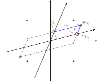
Fig-2:The idea of finding a proper radius
Fig. 2 shows the concept with a simple example of a 2 2 H. Solid points represent the transmitted QPSK symbols, and circles are the received lattice points, i.e., the transmitted symbols multiplied by the channel matrix. Line and represent the mid-lines between neighbouring points, and and are the two decision distances of . In this example, and are exactly the column norms of H, and is chosen as the initial radius of hyper sphere D.
It increases the radius when there exists no vector within a sphere, and decreases the radius when there exist multiple vectors within the sphere[8].
Fig-3:Basic Idea Behind Radius Reduction
In this example, this sphere includes four candidate vectors, one of which is the ML solution vector. We note that no vector outside the sphere can be the ML solution vector because their ML metric values are bigger than the ones inside the sphere. If we were fortunate to choose the closest one among the four candidate vectors, we can reduce the radius, so that we may have a sphere within which a single vector remains[1]. In other words, the ML solution vector is now contained in this sphere with a reduced radius, as illustrated in Figure 3(b).
[image:3.595.55.276.107.169.2] [image:3.595.334.499.110.249.2] [image:3.595.334.563.443.534.2]© 2017, IRJET | Impact Factor value: 5.181 | ISO 9001:2008 Certified Journal
| Page 1584
3. PROPOSED WORK
The fig.4 explain the process about Sphere decoder. Here the bits are sending from the transmitter part to receiver part via wireless channel. Assume the bits are X. it may be based on data rate. This bits are sending to the modulated symbol block. This block convert the bits into the symbols. Each symbol consist of few bits presented it based on the modulation technique. This symbols are transmitted via multiple antennas at the transmitter side. This antenna sends the symbols to the next block channel. Now we get the output form Hs. Here some noises are added with the output so we get Hs+n. here n is the Gaussian noise. This reaches the receiver side of the multiple antennas. Then this antenna sends the received symbols to the next section. Here the transmitted symbols are estimated with the help of the Euclidean distance of received symbols, channel and transmitted symbols.
̂ ‖ ‖ (9)
Fig-4: Flow Diagram of Sphere Decoder
Using this equation there is calculate the estimated values. Now using sphere decoder going to find the accurate transmitted symbols with low complexity[4]. Here only consider those symbols which are fall within the sphere. So number of searching nodes is decreases. In this method the complexity is reduced compare the other methods. And the symbols are converted to bits as they transmitted.
The sphere decoder is developed on two stages. Firstly a pre processing stage computes the QR factorization of the channel matrix, H and after this a search stage finds the estimation of transmitted symbol ̂
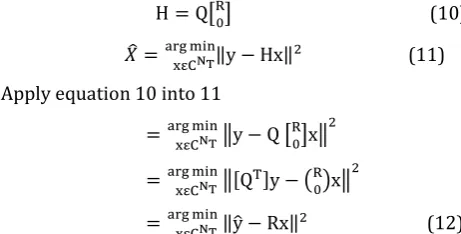
[ ] (10)
̂ ‖ ‖ (11) Apply equation 10 into 11
‖ [ ] ‖
‖[ ] ( ) ‖
‖ ̂ ‖ (12) Q is NxN and orthogonal, R is MxM, upper invertible and triangular, and 0 is an (N-M) x M matrix of zeros. As the
objective function is invariant under orthogonal transformation, minimization problem can be written as. Where ̂= [ ]y, the lower limit 1 and the upper limit M extract the first M elements of the orthogonally transformed target.
Sphere decoder achieves quasi-ML performance with average computational complexity for large range of SNR[4]. Instead of testing all possible transmitted vectors, SD restricts the search in to the lattice points that inside of sphere radius d.
̂ ‖ ‖ (13) The estimated value is must inside the sphere radius
̂ ‖ ‖ (14) The original sphere decoder, after the computation of the first point in the lattice, reduces the radius of the sphere to the value of the distance of this new point to the received point.
4. SIMULATION RESULTS
In this section there is showed that sphere decoder is good when compared to the other decoder such as zero forcing, minimum mean square error and maximum likelihood detectors. From the result clearly understand that, using Sphere Decoder, the SNR is above 15 we get the minimized BER of
Fig-5: Performance Comparison Results
[image:4.595.48.286.313.438.2] [image:4.595.316.546.450.582.2] [image:4.595.50.281.620.737.2]© 2017, IRJET | Impact Factor value: 5.181 | ISO 9001:2008 Certified Journal
| Page 1585
Fig-6: Complexity comparison of ML and SD MIMO using 64-QAM
Fig.6[4] shows The complexity is measured in terms of the number of real multiplication required to decode the transmitted complex symbols. The complexity reduction of 4QAM is 22%,and that of 16QAM,and 64QAM are 40%and 49% respectively. which shows that the complexity is reduced to a great extend as the level of modulation increases, while we adopt the proposed algorithm.
4. CONCLUSION
SD algorithm can significantly lower the computational cost of ML detectors by reducing the number of possible candidates before executing the final step of exhaustive search. In this paper we analysed performance and comparison of the MIMO detectors with sphere decoder .Our sphere decoder is robust to CSI errors and is near optimal in the sense of minimizing the probability of symbol error. We demonstrated, via simulations, that our sphere decoder incurs very small performance loss (when compared to the exact ML solution) with significantly lower computational complexity. Thus, our sphere decoder is implementable in practical MIMO systems. We also study about the complexity and performance of the MIMO decoders. In short, the modified SD algorithm constitutes an attractive option for practical MIMO receiver design.
REFERENCES
[1] Chin-Yun Hung and Tzu-Hsien Sang “A Sphere
Decoding Algorithm for MIMO Channels” 0-7803-9754-1/06©2006 IEEE
[2] Kailath. T, H.Vikaloz, and B. Hassibiz “MIMO Receive
Algorithms” Stanford University @California Institute of Technology
[3] Saranya.B “Sphere Decoder for Massive MIMO”
IJARECE Volume 5, Issue 2, February 2016
[4] Ramya Jothikumar “Reduce Complexity Analysis for
ML MIMO System”978-1-4673-5036-5/13@2013 IEEE
[5] Er. Navjot Singh, Er. Vinod Kumar “Linear and
Non-Linear Decoding Techniques in Multi-User MIMO Systems: A Review” Vol. 4, Issue 5, May2015 DOI 10.17148/IJARCCE.2015.4518
[6] Ammu.I, Deepa.R. “Comparative Study of the detection
algorithms in MIMO” IJCSET | June 2011 | Vol 1, Issue 5,222-226
[7] Liu Peng, Li Shuqing “The Maximum Likelihood
detection for MIMO Communications Systems” 978-1-4244-7161-4/10 ©2010 IEEE.
[8] Sonjuhi Mrinalee, Honey Priya Garg, Garima Mathur, R
P Yadav “Improved Radius Selection in Sphere Decoder for MIMO System” 978-93-80544-12-0/14/ 2014 IEEE.
[9] Receiver Architectures for MIMO Wireless