© 2018, IRJET | Impact Factor value: 6.171 | ISO 9001:2008 Certified Journal | Page 1457
Implementation of FPGA Based Image Processing Algorithm Using
Xilinx System Generator
Deepesh Prakash Guragain
1, Pramod Ghimire
2, Kapil Budhathoki
31,2Asst.Professor,Dept of Electronics and Communication Engineering, Nepal Engineering College, Bhaktapur Nepal 3E-Matrix Pvt. Ltd, Kathmandu, Nepal
---***---Abstract – This paper provides the method of image processing using Xilinx System Generator. Xilinx System Generator has necessary libraries to assist various types of algorithms. It is integrated with Matlab Simulink environment in this work. Model based design approach is used to implement various kinds of image processing algorithms. Hardware co-simulation is done to verify the results. The different image processing algorithms for RGB to gray scale, algorithm for image negatives, image enhancement, background subtraction, thresholding, erosion, dilation and masking are implemented using available System Generator blocks.
Key Words: Image Processing, Xilinx System Generator, Field Programmable Gate Array (FPGA), DSP, Matlab
1. Introduction
Image processing has wide applications from medical image processing to computer vision, digital photography, satellite imaging, digital encryption and decryption. The quality of image is considerably increased by image processing algorithms, which helps lot in medical imaging, surveillance and robotics application for target identification and tracking [1].
The need to process the image in real time is time consuming and leads to the only method of implementing the algorithm at hardware level. With FPGA implementations, the logic required by an application is implemented by building separate hardware for each function. Also FPGAs are inherently parallel; this gives the speed to those real time applications while retaining the programmable flexibility of software at a relatively low cost. This paper aims to implement image processing algorithms using Xilinx System Generator. The hardware implementation of the algorithms on FPGAs is done using model based design approach.
1.1 Xilinx System Generator
The Xilinx’s Generator is a System-level modeling tool from Xilinx that facilitates FPGA hardware design. It extends Simulink in many ways to provide a modeling environment well suited for hardware design. The software automatically converts the high level System DSP block diagram to RTL. The result can be synthesized to Xilinx’s FPGA technology using ISE tools, all of the downstream FPGA implementation steps
including synthesis place and route are automatically performed to generate an FPGA programming file. System Generator automates the design process, debugs, implement and verifies the Xilinx-based FPGAs. It provides a high speed HDL co-simulation interfaces which give up to a 1000x simulation performance increase. System Generator also supports a black box block that allows RTL to be imported into Simulink and co-simulated with either Modelsim or Xilinx ISE simulator [2].
1.2 Design flow for image processing using Xilinx System Generator
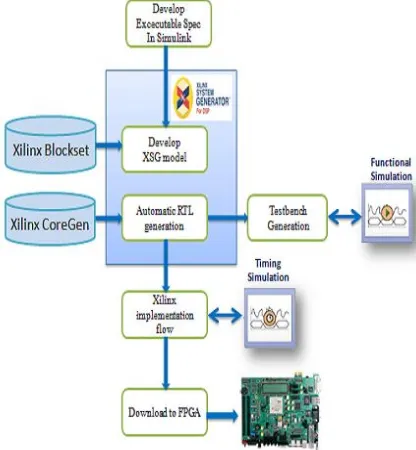
[image:1.595.344.552.495.720.2]The algorithms are developed and models are built using library provided by Xilinx Blockset. These models are simulated in Matlab/Simulink environment. The reflected result is viewed on a video viewer. The results obtained from System Generator are configured for suitable FPGA implementation. The behavioral model is verified, synthesized and implemented on FPGA. The Xilinx System Generator itself has the feature of generating user constraints file (.ucf), test bench and test vectors for testing architecture.
© 2018, IRJET | Impact Factor value: 6.171 | ISO 9001:2008 Certified Journal | Page 1458 number in a simulation. A double is a 64 bit 2’s complement
floating point number. Since this number system consumes lot of resources and is not efficient for FPGAs. The Xilinx blocksets uses n-bit fixed point numbers, thus a conversion is required when Xilinx blocks communicate with Simulink blocks [2].Gateway In, Gateway Out, and Sampling are used during this conversion.
3. Methodology of implementation of image processing in hardware
[image:2.595.312.550.299.373.2]All required hardware algorithms are implemented in between image pre-processing and image post-processing as depicted in Fig-2. Image source, image viewer, Image Pre-Processing and Image Post-Pre-Processing units are common for the entire image processing applications and they are implemented in Simulink.
Fig -2: Design flow of hardware implementation of image processing
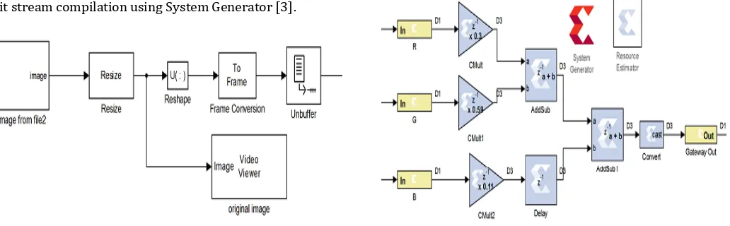
4. Image Pre-Processing Unit
Image pre-processing in Matlab helps in providing input to FPGA as specific test vector array which is suitable for FPGA bit stream compilation using System Generator [3].
Fig -3: Image Pre-Processing Unit
data is needed as FPGAs operate in one dimensional data only.
5. Image Post-Processing Unit
Image post-processing helps in recreating image from 1-D array. It consists of four blocks: Data Type Conversion, Buffer, Convert 1-D to 2-D, and video viewer. The first block converts image signal to unsigned integer format. Second block converts scalar samples to frame output at lower sampling rate. Third block converts 1-D image signal to 2-D image matrix. The last block is used to display the output image back on the monitor. Fig-4 depicts the Image Post-processing steps in block diagram form.
Fig -4: Image Post-Processing Unit
5.1: Algorithm for gray scale conversion
To minimize the processing time, color images are converted into grayscale level according to the color of each pixel that contains red(R), green (G), and blue (B) [4],[5]. The RGB image is converted to a grayscale image according to the following equation.
[image:2.595.36.284.337.473.2]Y=0.3*R + 0.59*G + 0.11*B
Fig-5 shows the algorithm in block diagram form.
[image:2.595.42.558.570.730.2]© 2018, IRJET | Impact Factor value: 6.171 | ISO 9001:2008 Certified Journal | Page 1459 Fig -6: Result obtained from Grayscale Image Conversion.
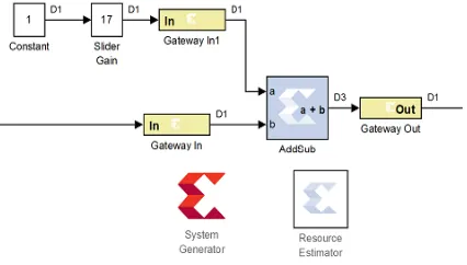
5.2 Algorithm for gray scale image negative
[image:3.595.336.549.298.419.2]Negative image is obtained by simply inverting the image matrix. Such produced image looks like the negative of the film. In Matlab, this is obtained by inverting the image source with NOT gate or by using Addsub block, subtracting one input by constant 255. Both the Addsub and NOT gate is available in Xilinx System Generator library which make steps simpler to use. The algorithm used is shown in Fig-8.
[image:3.595.51.261.383.532.2]Fig -7: Algorithm for Image Negative using Addsub Block for Gray scale Image
Fig -8: Algorithm for Image Negative using Inverter Block for Grayscale Image
Fig -9: Result obtained from Grayscale Negative
5.3 Algorithm for image enhancement
Image enhancement improves the interpretability or perception of information in images for human viewers [6],[7],[8]. Fig-11 shows the result obtained.
Fig -10: Algorithm for Grayscale Color Enhancement
Fig -11: Result for Grayscale Image Enhancement
5.4 Algorithm for Image contrast stretching
Grayscale image is stretched according to the equation.
New_ pixel =3(old pixel-127) +112
[image:3.595.338.548.452.561.2]where, New_pixel is its result after the transformation.
[image:3.595.61.276.585.724.2]© 2018, IRJET | Impact Factor value: 6.171 | ISO 9001:2008 Certified Journal | Page 1460 Fig -13: Result obtained from Grayscale Contrast
stretching
5.5 Algorithm for Image Thresholding
[image:4.595.55.266.76.214.2]Thresholding an image is the method of replacing each pixel in an image with a black pixel in the image intensity if it is less than some fixed constant value or white pixel if the image intensity is greater than that constant [9],[10]. Fig-14 shows the basic block diagram of thresholding while Fig-15 depicts the result that we implemented in the FPGA.
Fig -14: Algorithm for Grayscale image thresholding
Fig -15: Result of Grayscale Image thresholding
5.6 Background subtraction
[image:4.595.304.569.265.411.2]We use simple Addsub block to get the image of interest as shown in Fig-16 with the result that we obtained in Fig-17.
Fig -16: Algorithm for Grayscale Image background subtraction
Fig -17: Result obtained from background subtraction
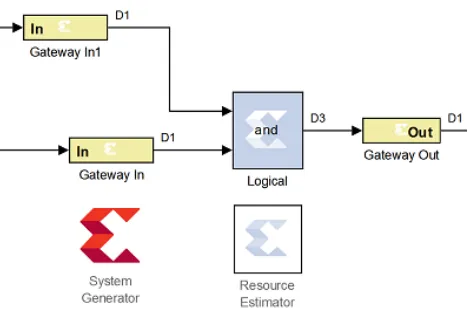
5.7 Erosion
In erosion, an object pixel is kept only if the structuring elements fit completely within the object; the output is considered as object pixel only if all of the inputs are one thus erosion is logical AND of the pixel within the window. The object size reduces because of erosion. Fig-18 and Fig-19 shows the block diagram form of the implementation of the erosion and the hardware implementation result.
[image:4.595.54.265.364.516.2] [image:4.595.55.273.548.674.2] [image:4.595.318.553.560.718.2]© 2018, IRJET | Impact Factor value: 6.171 | ISO 9001:2008 Certified Journal | Page 1461
Fig -19: Result obtained from erosion
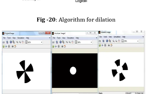
5.7 Dilation
[image:5.595.31.288.77.198.2]With dilation, each pixel is replaced by the shape of the structure element within the output image. 20 and Fig-21 indicates the block diagram of the dilation operation and the output that we obtained from the hardware implementation.
[image:5.595.311.557.268.403.2]Fig -20: Algorithm for dilation
Fig -21: Result obtained from Dilation algorithm
5.8 Algorithm for Edge detection
Edge detection is filtering and masking operation with suitable filter mask. Xilinx 5×5 filter provides coefficient for an Edge, Sobel X, Sobel Y, Sobel X-Y, Blur, Smooth, Sharpen, Gaussian filtering. For Filtering operation, the delay is created by 5×5 filter block to avoid this error since the System Generator has to be clocked 5 times faster than the normal clock. Fig-22 and Fig-23 demonstrates the block diagram and the FPGA output results.
[image:5.595.38.268.338.481.2]Fig -22: Algorithm for Edge detection for Grayscale Image.
Fig -24: Masking with setting of the background to black or white.
Fig -23: Result obtained from Edge detection
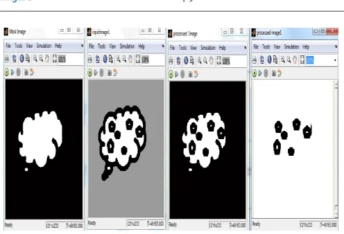
5.9 Masking
[image:5.595.37.276.436.591.2] [image:5.595.323.557.551.720.2]© 2018, IRJET | Impact Factor value: 6.171 | ISO 9001:2008 Certified Journal | Page 1462 Fig -25: Result obtained from Masking Algorithm.
6. Hardware/Software Co-Simulation in System Generator
System generator provides hardware co-simulation making it possible to incorporate a design running on an FPGA directly into Simulink simulation. When the system design is simulated in Simulink, result for the compiled portion are calculated in actual FPGA hardware, often resulting in significantly faster simulation time while verifying the functional correctness of the hardware.
7. Conclusions
Xilinx System Generator is integrated with Matlab Simulink for the real time image processing algorithms. Hardware co-simulation is used during the FPGA verification.
REFERENCES
[1] R.G.R. Woods, “Digital Image Processing”, New Jersey; Prentice-Hall, 2008
[2] “DSP System Generator User Guide” 12.1, 2012
[3] N.P.A.A.Gokhale, “FPGA Implementation for Image Processing Algorithms Using Xilinx System Generator”, IOSR Journal of VLSI and Signal Processing, vol.2(4),pp.26-36
[4] S. R. A. S. J.C.Moctezuma, "Architecture for filtering images using Xilinx System Generator," World Scientific Advanced Series In Electrical And Computer Engineering, Proceeding of the 2nd WSEAS International Conference on Computer Engineering and Applications, pp. 284-289, 2008.
[5] M. Ownby and M. W.H, "A Design Methodology for Implementing DSP with Xilinx System Generator for Matlab," IEEE International Symposium on System Theory., pp. 404-408, 2003.
Engineering and Emerging Technology , vol. 1, no. 7, pp. 40-47, August 2013.
[7] S. S. D. Praveen Vanaparthy, "FPGA Implementation of Image Enhancement Algorithms for Biomedical Image Processing," International Journal of Advanced Research in Electrical, Electronics and Instrumentation Engineering , vol. 2, no. 11, pp. 5747 - 5753, November 2013.
[8] T. S. F. S. a. M. A. Yahia Said, "Real Time Hardware Co-simulation of Edge Detection for Video Processing System," Laboratory of Electronics and Microelectronics (EμE) IEEE, pp. 852-855, 2012.
[9] E. Kuhn, "Grayscale Conversion of a Color Image Using Simulink and Xilinx Blocks," 2010.