© 2017, IRJET | Impact Factor value: 5.181 | ISO 9001:2008 Certified Journal | Page 1139
STUDY ON INFLUENCE OF POSITIONS OF CORE WALL FOR
STRUCTURES WITH STEP BACK CONFIGURATION
Vijayalakshmi Patel.K
1, Manjunatha.L
21
Post graduate Student, Structural Engineering, Department of Civil Engineering, SJB Institute of Technology,
Karnataka India
2
Assistant Professor, Structural Engineering, Department of Civil Engineering, SJB Institute of Technology,
Karnataka India
---***---Abstract -
Advancement of population growth andurbanization has widely recognized change of enormous number of multistoried structures which has led to disappearance of level land for improvement. So there is a requirement for construction on sloped ground. Structures constructed on slopes are not quite the same as in plane land. When influenced by seismic tremor, they are sensitive to extreme damage as they might be unpredictable and unsymmetrical in level and torsionally coupled. It is hard to counteract seismic tremors yet; impact can be decreased by safe design.
In multi storied structures, core wall are generally used for encompassing the lift rooms and are to be established correctly. Henceforth in the present review, an effort is made to examine the outcomes of position of core walls on level ground and inclined ground. Using ETABS, a steel building model with G+ 20 storeys is developed and a time history method with Zone V using medium soil condition is done. Perfect position of core wall is appropriately determined and seismic reaction parameters are inspected.
Key Words: Buildings on slopes, Core wall, Torsion, Displacements,.…
1. INTRODUCTION
Urbanization and economic expansion in hilly areas has increased land improvement and brought about increment in population rise excessively which has resulted in rise in interest for multi storied structures. Due to seismic tremor, sloped structures act unique in relation to those in plane ground when subjected to horizontal loads. Focal points of mass and rigidity do not concur on different floors as these structures have varied mass and stiffness.
Meanwhile, tremor seen in Sikkim and north eastern parts of India is indicative that structures on sloping ground are prone to high level of demolition but they have been intended for security of occupiers against normal risk. Subsequently while building the structures on hilly areas, attention ought to be kept for making these structure seismic safe.
Structures on sloped ground have stiff columns on hill side which attracts excessive amount of horizontal forces and is accountable to damage. Amid tremor, these structures evolve extremely large twisting moment. Short and Long column of proportionate area moves on a level ground with same magnitude.
Various researches on the sloping ground have been studied. Effort have been made on understanding the performance of buildings by making use of a constant angle of the slope and then comparing with the plain ground Birajdar et al (2004)[1]studiedthree dissimilar structural configurations with one building model on level ground and other two building on sloped ground with sloping angle maintained at 20 degree were assessed through response spectrum method and twisting impacts were comprised. Sloped buildings with varying slopes are also examined. In sloped structures, columns on the peak side are stiff deriving immense forces revealing short column effect. It is also identified that shearing performance in step back and set & step back buildings are comparatively on higher end when distinguished with setback configuration Kiran et al (2017)[2]reviewed on G+12 storey building with dissimilar sloping angles by performing linear static & response spectrum. It was observed as the sloping angle increases the base shear and storey drifts rises when compared with lower sloping angles. Research is also conducted by varying the storey heights for a uniform sloping angle. Birajdar et al (2004) [1] varied the storey heights from four to eleven using an angle of slope of 20 degree. It is established that the displacements & time period upsurges with rise in the number of floor level.
© 2017, IRJET | Impact Factor value: 5.181 | ISO 9001:2008 Certified Journal | Page 1140
resistance to seismic forces and also lift core at middle aredesirable than edges. Investigations have been done for different shapes of shear walls placed for a sloped building. Sandip Doijad et al (2015) [5] observed for various arrangement of shear walls resting on level ground for different sloping angles varying as 9, 18, 27 degrees. Buildings were studied for response spectrum method and observed that insertion of shear wall in building diminishes displacements along level and inclined ground and base shear intensifies in x & y direction.
2. OBJECTIVES OF THE STUDY
The earthquake action of steel structure with step back configuration are examined
To inspect the consequence of several positioning of core walls in steel structure for step back building.
To identify providing of core wall at satisfactory position for bearing the lateral loads proficiently.
To evaluate many parameters of the analysis like time period, twisting moments etc.
3. MODELLING
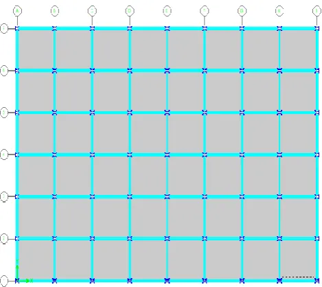
[image:2.595.355.509.111.329.2]From the study, a step back steel structure is developed in ETABS software. Step back building bearing 30.96 degree sloping angle is employed and time history method of examination is done with a structure found in zone V with medium soil.
[image:2.595.330.540.380.632.2]Figure 3.1: A plain view of steel step back building
Figure 3.2: Elevation of set & step back structure
Figure 3.3: A 3D view of step back building
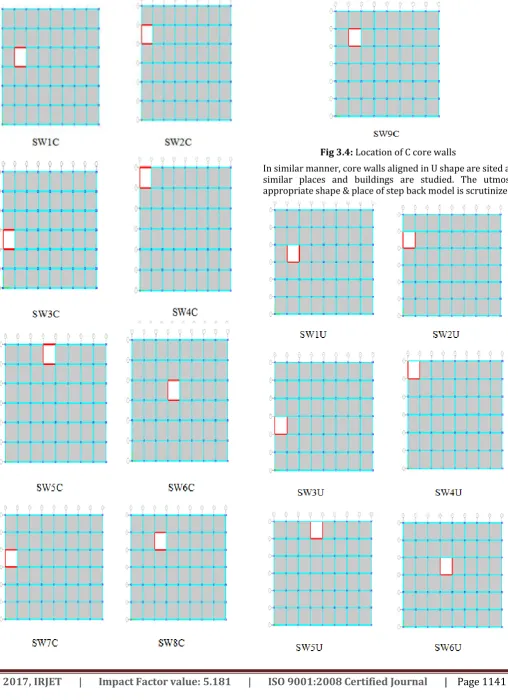
3.1 Locating core walls
[image:2.595.37.272.439.648.2]© 2017, IRJET | Impact Factor value: 5.181 | ISO 9001:2008 Certified Journal | Page 1141
Fig 3.4: Location of C core walls© 2017, IRJET | Impact Factor value: 5.181 | ISO 9001:2008 Certified Journal | Page 1142
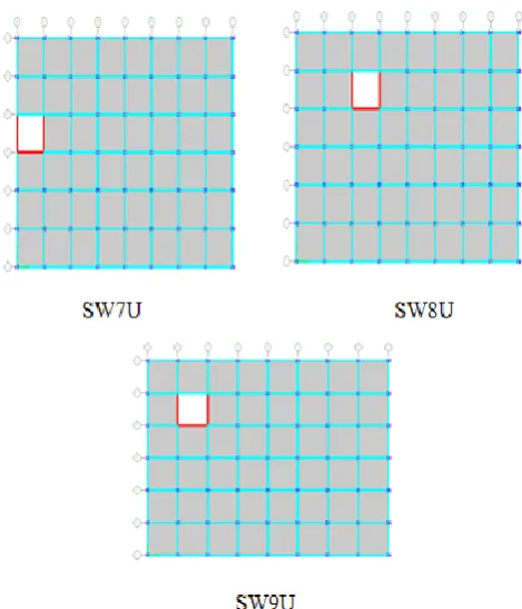
Fig 3.5: U core walls placed at different positions3.2 Material & Geometric Properties
[image:4.595.311.554.280.725.2]Various properties used for the developing of the step back structures-
Table 3.1: Details of various properties used
4. RESULTS AND DISCUSSIONS
Results obtained are developed in form of graphs for evaluating purposes and below are the results drawn
4.1 Displacements
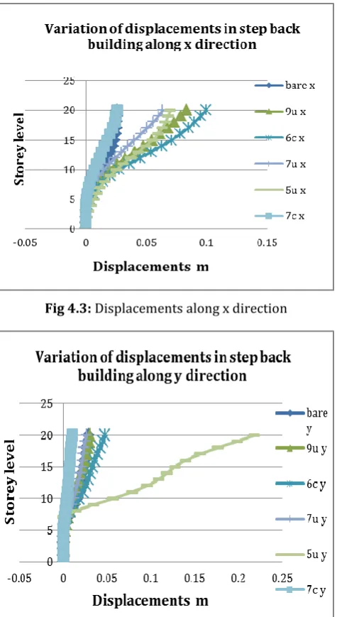
[image:4.595.28.557.289.761.2]It is sighted from examining the various location of core walls that sw7c imparts fewer displacements nearly 5.18% & and 64.80% smaller than bare models in x & y direction respectively. Henceforth of many positions evaluated sw7c has the least displacement and can be considered suitable.
Table 4.1 Maximum displacement along x and Y direction for step buildings
[image:4.595.41.277.458.747.2]© 2017, IRJET | Impact Factor value: 5.181 | ISO 9001:2008 Certified Journal | Page 1143
4.2 Torsion
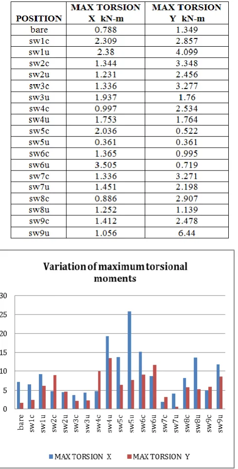
[image:5.595.94.529.181.734.2]Examining altogether the location of core walls aligned in C & U shape, sw7c produces 74% less significant torsion and 1.55% more twisting moment than bare model for seismic loads in x & y direction respectively. So sw7c is suggested as right position for step back buildings
Table 4.2 Torsional response of step back structures
Fig 4.2 Maximum torsion in step back structures
Viewing the torsional moments & displacements for many shapes & positions of core wall, it is observed that sw7c is
proven as an applicable position for step back structures. Besides sw5u, sw9u, sw6c and sw7u are few significant positions considered for complete study
Henceforth a complete investigation is prepared for these 5 positions chiefly sw5u, sw9u, sw6c, sw7c & sw7u.
sw7u sw7c
sw5u sw6c
[image:5.595.39.284.218.700.2]© 2017, IRJET | Impact Factor value: 5.181 | ISO 9001:2008 Certified Journal | Page 1144
4.3 Examining core wall positions
4.3.1 Displacements at different storeys for step
back structures
[image:6.595.315.553.164.344.2]The maximum displacements are commonly seen at top floors. The bare model has 25.68mm & 28.69 mm along x and y direction. In contrast with the buildings with core walls, position sw7c has smaller displacements from rest positions of core wall which is 0.7% more in x direction & 64.5% lesser displacements when compared with bare model displacements for x & y direction.
[image:6.595.44.282.244.679.2]Fig 4.3: Displacements along x direction
Fig 4.4: Displacements along y direction
4.3.2 Natural time period
The building lacking with incorporation of core wall has displayed higher values for time period implying more likely
to damage. Presence of the core walls has seen reduction in time period by 26.4% -65.76% in contrast with bare model suggesting that the decrease in time period helps in improving the structure to handle more seismic input frequencies
Fig 4.5: Time period variation.
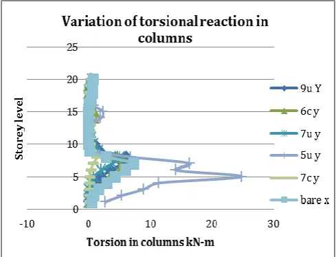
4.3.3 Variation of torsion in step back structures
In step back buildings, it is seen that the maximum column twisting are commonly seen at hill side and the columns c7 & c66 in bare models have twisting moments of 7.3kN-m and 1.28kN-m for seismic load in x & y direction. Among many positions, sw7c has about 74% lesser values & 1.5% more values for seismic loads in x & y direction when related with bare models. Since this produces the least torsion in columns this position is treated appropriate
[image:6.595.42.285.251.449.2] [image:6.595.309.556.491.695.2]© 2017, IRJET | Impact Factor value: 5.181 | ISO 9001:2008 Certified Journal | Page 1145
Fig 4.7: Torsion in columns for seismic load y direction5. CONCLUSIONS
a. A step back building encompasses changing length of columns, greater torsion is felt on the columns positioned on hill side of inclined ground, were shorter columns pulls more seismic forces leads to short column effect.
b. Looking through time period outcomes of several models, it is noticeable that comprising core walls in structures diminishes the fundamental time period of buildings consecutively increasing the stiffness of structure to draw a high level of input frequencies of seismic tremor. In existence of core walls, structures have displayed a time period by 26.28%-65.71%.
c. Displacement results exhibits sw7c produced a slightly higher value of 0.69 % in x direction & 64.48% smaller values in y direction than bare models. And so sw7c is treated as suitable location. d. Torsion results shows that, maximum torsional moments are seen in columns on upper side of sloping ground. Maximum values for bare model are encountered for columns c7 and c66 located on the higher slope end. While locating the suitable location of core wall it was seen that sw7c with column c66 exhibited lesser values of torsion than bare models. Hence sw7c is considered better. e. Finally it is inferred as sw7c is epitome position for
core walls for step back buildings.
REFERENCES
[1] Birajdar B. G,Nalawade .S.S “Seismic Analysis Of
Buildings Resting On Sloping Ground”,13th World Conference on Earthquake Engineering, Vancouver, B.C, Canada, August 1-6,2004,Paper No.147
[2] Kiran.T, N.Jayaramappa “Seismic Performance of RC
Frame Buildings Resting on Sloping Ground”, Volume 14,Issue 2,April 2017,pp 67-74
[3] Dr.S.H.Mahure and Amit S.Chavhan, “Vertical
Irregularities in RC Building Controlled By Finding Exact Position of Shear Wall”, International Journal of Innovative Research in Science Engineering and Technology, Volume 4, Issue 7, July 2015
[4] Rupali Goud and Sumit Pahwa , “Study of Effect of
Location of Lift Core Shear Wall under earthquake loads”, International Journal of Science Technology & Engineering, Volume 2,Issue 07,January 2016
[5] Sandip Doijad, Surekha Bhalachandra, “Seismic Behavior
of RC Buildings Constricted on Plain and Sloping Ground with Different Configuration of Shear Walls”, Journal of Civil Engineering and Environmental Technology, Volume 2,Number 10,April-June ,2015 pp.59-65
[6] Moulshree Tripathi, Mary Williams P and Dr.R.K.Tripathi
“Behavior of Tall Structures with Eccentric Loading”, International Journal of Research in Chemical, Metallurgical and Civil Engg. Volume 3, Issue 2, (2016)
[7] Lakshmi K.O, Prof. Jjayasree Ramanujan, Mrs.Bindu