© 2016, IRJET | Impact Factor value: 4.45 | ISO 9001:2008 Certified Journal
| Page 1326
Modeling and Investigation of Change in Working Parameters on the
Performance of the Vortex Tube with CFD Analysis
Sachin Godse
1, Devendra singh Sikarwar
21
P.G.Student,Mechanical Engineering, Patel college of science and technology ,Indore M.P, India
Associate Professor, Mechanical Engineering, PCST, Indore
---***---Abstract -
Refrigeration plays an important role in developing countries, primarily for the preservation of food, Medicine, and for air conditioning. Conventional refrigeration systems are using Freon as refrigerant. As they are the main cause for depleting ozone layer, extensive research work is going on alternate refrigeration systems. Vortex tube is a non-conventional cooling device, having no moving parts which will produce cold air and hot air from the source of compressed air without affecting the environment. When An experimental investigation has been performed to realize thorough behaviour of a vortex tube refrigeration system. The simple counter flow vortex tube consist of long hollow cylinder with a tangential nozzle at one end for injecting the compressed air has been designed, manufactured and tested. The vortex tube is a without affecting environment. It has capability to separate hot and cold air stream from a high pressure inlet air without any external energy supply or chemical reaction; such phenomenon is called as temperature or energy separation process.The vortex tube performance depends on two types of parameters, firstly air or working parameters such as inlet pressure of compressed air, cold mass fraction and secondly tube or geometric parameters such as length of hot side tube, cold orifice diameter, number of nozzles, diameter of nozzle, cone valve angle and also material of vortex tube affects Coefficient of Performance (COP). This paper discusses the experimental investigation of effect of above working parameters on the performance of Ranque Hilsch vortex tube. The paper develops three dimensional flow domain using Computational Fluid Dynamics (CFD) and this CFD and experimental studies are conducted towards the optimization of RHVT.. The L/D ratio of hot side tube varied from 10-50.
Key Words:
Vertex tube , optimization, COP,CFD,Geometric parameter. 1.INTRODUCTION Background
The vortex tube was invented in 1933 by French physicist Georges J. Ranque. German physicist Rudolf Hilsch
improved the design and published a widely read paper in 1947 on the device, which he called a Wirbelrohr (literally, whirl pipe).The vortex tube was used to separate gas mixtures, oxygen and nitrogen, carbon dioxide and helium, carbon dioxide and air in 1967 by Linderstrom-Lang.Vortex tubes also seem to work with liquids to some extent, as demonstrated by Hsueh and Swenson in a laboratory experiment where free body rotation occurs from the core and a thick boundary layer at the wall. Air is separated causing a cooler air stream coming out the exhaust hoping to chill as a refrigerator.In 1988 R.T.Balmer applied liquid water as the working medium. It was found that when the inlet pressure is high, for instance 20-50 bar, the heat energy separation process exists in incompressible (liquids) vortex flow as well. Note that this separation is only due to heating; there is no longer cooling observed since cooling requires compressibility of the working fluid.Vortex tube is a simple energy separating device which is compact, simple to produce and to operate. Although intensive research has been carried out in many countries over the years, the mechanism producing the temperature separation phenomenon as a gas or vapour passes through a Ranque-Hilsch vortex tube is not yet fully understood.
1.1 Problem statement
© 2016, IRJET | Impact Factor value: 4.45 | ISO 9001:2008 Certified Journal
| Page 1327
1
1.2 Problem Formulation
Theoretical explanation is given by various papers in different way. They have tried to explain as how does the pumping of heat from compressed air temp to high temperature takes place in absence of a mechanical device. When compressed air is passing through the nozzle in the vortex chamber inside the chamber high velocity swirl motion is created. The air moves as a free vortex from the nozzle plane towards the valve end. As it near the valve, the kinetic energy is converted into the pressure energy giving a point of stagnation. But the stagnation pressure is higher than the pressure in the nozzle plane; thereby the reversal in flow takes place. This reversed flow comes in contact with forward moving free vortex, which causes the reversed vortex flow to rotate with it. Heat exchange takes place between these two flows The problem identification, objective and hypothesis has been prepared in previous sections now to devise the problem the parabolic leaf spring taken into consideration
2 .Working Principal
Temperature Separation
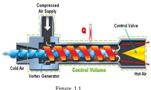
[image:2.595.319.580.97.252.2]The vortex tube creates two vortices forced and free. The free vortex fluid particle is moves towards the center of vortex and the angular velocity is fast at the center. In forced vortex particle velocity is directly proportional to the radius of the center vortex and is slower at that placed. In vortex tube outer vortex is free and the inner vortex is forced .The rotational motion of the forced vortex is controlled by free vortex. The turbulence of both the hot and cold air streams causes the layers to be locked together in a single, rotational mass. The inner air stream flows through the hollow core of the outer air stream at a slower velocity than the outer air stream
Figure .1.1
Since the energy is proportional to the square of the velocity, the cold air stream loses its energy by heat transfer. This allows energy to flow from the inner air stream to the outer air stream as heat creating a cold inner air stream.
3 Components of the Vortex Tube
Main body
Figure 3.1 (a) Main Body
It is connecting part of hot tube and cold tube. Length of main body 60mm and diameter is 29mm.The inlet is connected over the main body. The material of this part is PVC and mild steel.
Cold tube:
Figure 3.2 (b) Cold Tube
It is a smaller than hot tube. Diameter of this tube is 29mm and length is 80mm.Material of this tube is mild steel or PVC.
© 2016, IRJET | Impact Factor value: 4.45 | ISO 9001:2008 Certified Journal
| Page 1328
Figure 3.3 (c) Hot Tube
It is main part of the vortex tube. Material of this tube is mild steel or PVC .Diameter of this tube is 29mm and length is 105mm.At the one end of this tube control valve is placed.
Control valve:
Figure 3.4 (d) Control Valve
The function of the control valve is to control the hot air discharge. Cold effect of this vortex tube is depends on the opening of the control valve. Material of this valve is M.S or wood. The angle of control valve is up to 45 degree.
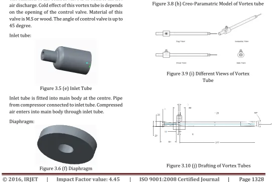
Inlet tube:
Figure 3.5 (e) Inlet Tube
Inlet tube is fitted into main body at the centre. Pipe from compressor connected to inlet tube. Compressed air enters into main body through inlet tube.
Diaphragm:
Figure 3.6 (f) Diaphragm
It is the thin part of the vortex tube. Material of the diaphragm is M.S. The 8mm diameter hole is drill on canter of diaphragm plate. Thickness of this diaphragm is 6mm.
Nozzle:
Figure 3.7 (g) Nozzle
Nozzle is used for passing the high velocity air as a input of the vortex tube. The diameter of the nozzle is 9mm. A tangential cut is given to the nozzle by using a hacksaw blade.
Figure 3.8 (h) Creo-Paramatric Model of Vortex tube
Figure 3.9 (i) Different Views of Vortex Tube
[image:3.595.38.575.34.843.2] [image:3.595.396.498.172.262.2] [image:3.595.128.196.262.393.2] [image:3.595.335.575.334.425.2] [image:3.595.31.576.430.792.2] [image:3.595.99.224.505.605.2]© 2016, IRJET | Impact Factor value: 4.45 | ISO 9001:2008 Certified Journal
| Page 1329
4. Computational Fluid Dynamics
Computational Fluid Dynamics, Computational – mathematical analysis, computing Fluid Dynamics - the dynamics of things that flow CFD - a computational technology that enables one to study the dynamics of things that flow. CFD is concerned with numerical solution of differential equations governing transport of mass, momentum and energy in moving fluid. Using CFD, one can build a computational model on which physics can be applied for getting the results. The CFD software gives one the power to model things, mesh them, give proper boundary conditions and simulate them with real world condition to obtain results. Using CFD a model can be developed which can breed to give results such that the model could be developed into an object which could be of some use in our life.
4.1 The Benefits of CFD
There are three reasons to use CFD software: insight, foresight, and efficiency.
4.2 Insight
Think of an object which is difficult to produce practically and do some experiment on it. CFD provides the break through. Using the CFD software, one can easily design the object and use the boundary conditions to get output. The simulation thus helps in getting results much easily than constructing the real object.
4.3 Foresight
In CFD first we make the model then use certain boundary conditions to get the output. Thus using CFD we can give some real world condition say as pressure or temperature and simulate things to get the output. Many variations can be adopted till an optimal result is reached. All of this can be done before physical prototyping and testing.
4.4Efficiency
The analysis gives better idea of, how the object works. So necessary changes could be brought about to facilitate better production of the product. Thus CFD helps to design better and faster bringing about improvement in each step.
4.5 The CFD Process
In the past decades many modeling and simulation software have been developed like PHONICS, FLUENT, SRAT-CD, CFX, FLOW -3D and COMPACT. Generally this software’s are based on finite volume method. FLUENT is one of the major software which has helped a lot in modeling fluid and heat transfer problems.
5. Observation.
5.1 Model No. 1
Nozzle diameter (D n) =13 mm No of inlet = 1
Diaphragm diameter= 7mm Length of tube (L) =377mm Diameter of tube (D) = 24mm Sr.
No. Pressure (bar) Inlet temp. (ti) Hot end temp (th) Cold end Temp. (tc) Temp. Diff. (th-tc)
1 6.5 – 3 28.5 33 16.9 16.1
2 5 – 3 28.3 32.2 17.2 15
3 4.5 – 3 28 31 18 13
Observation for Model No. 1 5.2 Model no. 2
Nozzle diameter (D n) =13 mm No of inlet = 1
Diaphragm diameter= 7mm Length of tube (L) =348mm Diameter of tube (D) = 24mm
Sr. no . Pressur e (bar) Inlet temp. (ti) Hot end temp. (th) Cold end Temp. (tc) Temp. Difference (th-tc) 1 6.5 – 3 28.5 30.7 18.6 12.1
2 5 – 3 28.3 30 19.1 10.9
3
4.5
– 3
28
29.8
20.5
9.3
Table 7.2 Observation for Model No. 2
5.3 Model no. 3
© 2016, IRJET | Impact Factor value: 4.45 | ISO 9001:2008 Certified Journal
| Page 1330
No of inlet = 1
Diaphragm diameter= 7mm Length of tube (L) =319mm Diameter of tube (D) = 24mm Sr.
no.
Press ure (bar)
Inlet temp.
(ti)
Hot end temp.
(th)
Cold end Temp.
(tc)
Temp. Difference (th-tc)
1 6.5 – 3
28.5 30.3 19.8 10.5
2 5 – 3 28.3 29.9 20.2 9.7
3 4.5 – 3
28 29.5 20.6 8.9
Table 7.3 Observation for Model No. 3
[image:5.595.27.571.56.300.2]6. RESULTS AND DISCUSSION
6.1 Practical Result
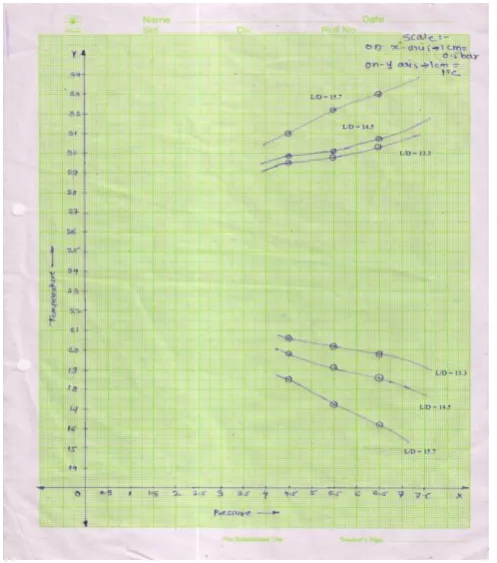
Figure 6.1 Pressure Vs Temperature
6.2 Ansys Result
Figure 6.2 CFD Result Cold side temperature = 294 K
Hot side temperature = 300 K Inlet temperature = 297 K 7. CONCLUSION
The study was conducted with a simple, in house fabricated vortex tube with the aim for obtaining correct thermodynamic results. The equipment designed was for the best results i.e. Least temperatures, but for more accurate results. Nevertheless the equipment worked as desired and the readings were obtained. Vortex tube is used for utilizing the waste compressed air which is produced in various industrial applications. For this tube if we use a separate compressor then the complete process is not so efficient, just because of low COP.
From the graph, it is conclude that at high pressure we get more temperature difference. As pressure decreases temperature difference also decreases.
REFERENCES
[1] Sankar Ram T. and Anish Raj K., An Experimental Performance Study of Vortex Tube Refrigeration System, An Experimental Performance Study of Vortex Tube Refrigeration System | ISSN: 2321-9939
[image:5.595.66.315.420.702.2]© 2016, IRJET | Impact Factor value: 4.45 | ISO 9001:2008 Certified Journal
| Page 1331
Engineering (IOSR-JMCE) ISSN(e) : 2278-1684, ISSN(p) : 2320–334X, PP : 45-49
[3] Suraj S Raut, Dnyaneshwar N Gharge, Chetan D Bhimate, Mahesh A. Raut, S.A. Upalkar and P.P.Patunkar, An Experimental Modeling and Investigation of Change in Working Parameters on the Performance of Vortex Tube, International Journal of Advanced Mechanical Engineering. ISSN 2250-3234 Volume 4, Number 3 (2014), pp. 343-348