© 2016, IRJET | Impact Factor value: 4.45 | ISO 9001:2008 Certified Journal | Page 2202
ELIMINATION OF HARMONIC RESONANCE USING HYBRID ACTIVE
FILTER UNIT WITH VARIABLE CONDUCTANCE.
N.Anandan
1*,T.M.Thamizh Thentral
2and R.Jegatheesan
21Department of Power Electronics and Drives,SRM University,India-603203. 2Department of Electrical and Electronics Engineering,SRM University,India-603203.
---***---Abstract -
Abstract—
Harmoni c distortion is
mainly due to the tuned passive filter and line
inductance which produces resonances in the
industrial system. To suppress this above problem
hybrid active filter is used. The proposed hybrid
filter is operated as variable conductance
according to the total harmonic distortion in
voltage and current. Thus harmonic distortion can
be reduced to an acceptable level in the power
system. The hybrid active filter is a combination of
seventh tuned passive filter and an active filter in
series connection so that the VA rating of the
active filter and the dc voltage of the active filter
are reduced to acceptable levels and in addition to
that hybrid active filter is used because of its
filtering capability and the cost. A Design
consideration is presented and experimental
results are provided to validate the effectiveness
of the proposed method.
Keywords
— Harmonic resonance, Hybrid active
filter,
1.
INTRODUCTIONThe extensive usage of nonlinear loads such as adjustable speed drives, uninterruptable power supply and battery charging system increases the harmonic pollution. The diodes or rectifiers are used to realize the power conversion because of lower component cost and its simplicity. Moreover rectifiers allow a large amount of harmonic current flow in the system. This excessive power flow produces harmonic distortion which may give rise to malfunction of sensitive
equipment. Normally tuned passive filter are located at the secondary side of the distribution transformer to provide low impedance for controlling harmonic current and to correct the power factor for harmonic loads[1],[2].To provide the parametric changes in the passive filters, results in unintended series or parallel resonances that may occur between the passive filter and the line inductance. The functionality of passive filter may become progressively worse and extra calibrating work is needed to maintain the filtering capability.[3],[4].
Various active filtering technique have been presented to indicate the harmonic issues in the power system [5]-[7].The active filter is used for compensating harmonic currents of non-linear loads, but this may not be effective. To improve the performance of the passive filter “active inductance” hybrid filter was introduced [10].Thefifth harmonic resonance is present between the power system and the capacitor bank. In order to suppress that fifthharmonic resonance a hybrid shunt active filter with filter –current detecting capability was used
.
The combination of both the active and the passive filter in series with the capacitor bank by coupling a transformer was used to reduce the harmonic resonance and to balance the harmonic current.[12],[13].This method needs extra transformers or tuned passive filter to maintain the filtering capability© 2016, IRJET | Impact Factor value: 4.45 | ISO 9001:2008 Certified Journal | Page 2203 and the inductance is not considered in the system.
The fixed conductance may deteriorate the damping performances. An anti-resonance hybrid filter for delta-connected capacitor bank of power-factor-correction applications is presented [21]. This in circuit was limited to three single-phase inverters, and the filtering performance was not considered. In addition, the hybrid active filter was proposed for the unified Power Quality (PQ) conditioner to address PQ issues in the power distribution system [22]. Several case studies of the hybrid active filter considering optimal voltage or current distortion were conducted in [23].
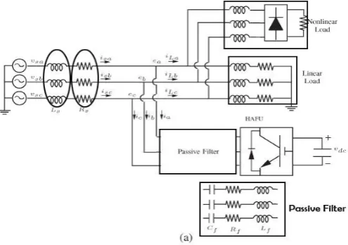
Fig 1(a) Proposed System
1.1 Operating principle
Fig 1(a)shows a simplified circuit diagram considered in
this paper, where Ls represents the line inductance plus the leakage inductance of the transformer. The Hybrid Active Filter Unit (HAFU) is constructed by a seventh-tuned passive filter and a three-phase voltage source inverter connected in series connection. The passive filteris intended for compensating harmonic current and reactive power. The inverter is designed to suppress harmonic resonances and to improve the filtering performances of the passive filter.
1.2 HARMONIC LOOP
To suppress harmonic resonances, the HAFU was proposed to operate as variable conductance at harmonic frequencies as follows:.
L*h= S* · eh (1) where L*hrepresents the current harmonic command.
The conductance command S* is a variable gain to provide damping for all harmonic frequencies. Harmonic voltage component ehisobtained by using the SRF transformation [9], where a Phase-Locked Loop (PLL) is realized to determine the fundamental frequency of the power system [28]. In the SRF, the fundamentalcomponent becomes a dc value, and other harmoniccomponents are still ac values. Therefore, harmonic voltagecomponent eeqd,h can be extracted from eeqd using highpassfilters.
1.3 FUNDAMENTAL LOOP
In the paper, the q-axis is aligned to A-phase voltage. Since
the passive filter is capacitive at the fundamental frequency, the passive filter draws leading current from the grid, which is located on the d-axis. The proposed inverter produces the low voltage on the d -axis, which is in phase with the leading current. Therefore, the control of dc bus voltage can be accomplished by exchanging real power with the grid. Thus, the current command ied*f is obtained by a proportional–integral (PI) controller. The fundamental current command i*f in the three-phase system is generated by applying the inverse SRF transformation The harmonic voltage drop on the passive filter due to the compensating current of the HAFU [20], where I represents the maximum harmonic current of the active filter, and the voltage drop on filter resistance Rf can be neglected. As can be seen, a large filter capacitor results in the reduction of the required dc voltage. The filter capacitor determines reactive power compensation of the passive filter at the fundamental frequency. Thus, the dc voltage v*dc can be determined based on this compromise. Note that the compensating current should be limited to ensure that the hybrid filter operates without undergoing saturation, i.e.,
[image:2.595.39.287.287.461.2]© 2016, IRJET | Impact Factor value: 4.45 | ISO 9001:2008 Certified Journal | Page 2204
1.4 CURRENTREGULATOR
The current command i*consist ofi**h and i*f Based on the current command i*and the measured current i, the voltage command v* can be derived by using a proportional controller
as follows:
v*=KC.(I*-i) (2)
Where Kc is a proportional gain. According to the voltage
command v∗, space vector pulse width modulation
(PWM) is employed to synthesize the required output voltage of the inverter.The computational delay of digital signal processing is equal to one sampling delay T, and PWM delay approximates to half the sampling delay T/2. Hence, the proportional gain Kc can be simply evaluated from both open loop and closed-loop gains for suitable stability margin and current tracking capability.
2 EXPERIMENTAL VERIFICATION
The filtering performance of HAFU designed by using equivalent circuit models. The passive filter equivalent harmonics has been changed by harmonic conductance so that the unintentional resonances can be avoided. Here the major concentration is on THD*.
To compensate the inductive loads a capacitor has been used .A filter inductor was chosen to balance the LC filter resonant. The three phase of the inverter is short circuited so that OFF state HAFU corresponds to turning on three upper switches and turning off of three lower switches. At this moment, HAFU acts as a pure passive filter.
2.1 THREE PHASE LOAD
In the case of three phase load system, the filter is designed using pq theory. When HAFU Is in OFF state HAFU becomes a passive filter.
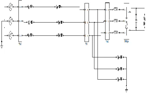
Fig 2(a) Simulation circuit without filter
Fig 2(b) source voltage waveform
[image:3.595.315.554.121.275.2] [image:3.595.308.558.328.467.2]© 2016, IRJET | Impact Factor value: 4.45 | ISO 9001:2008 Certified Journal | Page 2205
Fig 2(d) load voltage waveform
The simulation was done for the linear loads and the non linear loads and when the HAFU is off the harmonics caused by both loads are very high. In fig2(b) and 2(c) shows the disturbances produced in the sinusoidal waveform which is due to the harmonic disturbance.
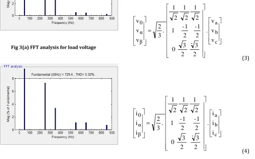
Fig 3(a) FFT analysis for load voltage
Fig 3(b).FFT analysis for load current
TABLE 1
Harmonic distortion for non-linear load (a)Load voltage (b)Load current
THD H5 H7 H9 H11
HAFU
OFF 8.34 7.32 3.41 0.001 1.16
HAFU
ON 2.76 2.72 1.71 0.07 0.50
THD H5 H7 H9 H11
HAFU
OFF 8.38 7.90 2.63 0.001 0.58 HAFU
ON 4.73 2.24 0.93 0.06 0.23
The filter was designed using PQ theory to reduce the harmonics. From the results shown in Table 1,it is clear that with HAFU, harmonic content in load voltage and load current reduces considerably.
[image:4.595.51.284.334.495.2] [image:4.595.50.550.434.747.2]© 2016, IRJET | Impact Factor value: 4.45 | ISO 9001:2008 Certified Journal | Page 2206 The p-q theory consists of an algebraic transformation
(Clarke transformation) of the three-phase voltages and currents in the a-b-c coordinates to the α-β-0 coordinates, as shown in equations (3) and (4).The power components are related to voltage and current and the equation is shown as follows
β
α
α
β
β
α
i
i
.
v
v
v
v
q
p
(5) To calculate the reference compensation currents in the α-β coordinates, the equation (5) is inverted, and thepowers to be compensated is shown as follows
q
p
p
.
v
v
v
v
.
v
v
1
i
i
0 α β β α 2 β 2 α * cβ * cα (6)Finally the reference compensation current in the a-b-c co-ordinates are obtained through the inverse of transformation * cβ * cα * c0 * cc * cb * ca i i i . 2 3 2 1 2 1 2 3 2 1 2 1 0 1 2 1 3 2 i i i (7)
By the following steps, the PQ theory based filter is designed, and the overall THD is reduced.
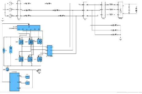
Fig 4(a) simulation circuit with filter blocks
Fig 4(b) PQ theory control blocks
[image:5.595.311.542.139.292.2] [image:5.595.326.532.364.529.2]© 2016, IRJET | Impact Factor value: 4.45 | ISO 9001:2008 Certified Journal | Page 2207 Fig 4(d) load voltage waveform
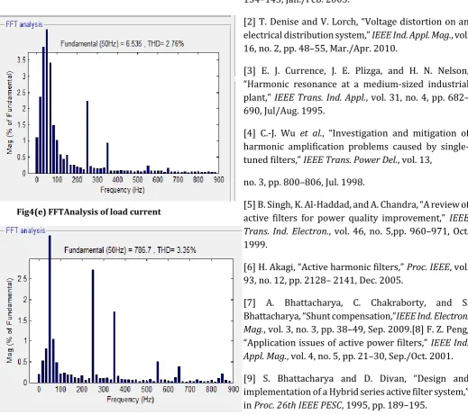
Fig4(e) FFTAnalysis of load current
Fig 4(f) FFTAnalysis Of load voltage
IV. CONCLUSION
In yhis paper the role of Hybrid Active Filter unit to suppress the harmonic distortion is discussed.The hybrid active filter is composed of the seventh harmonic tuned passive filter and an active filter in series connection.With the active filter operating as variable harmonic conductance, the filtering performances of the passive filter can be significantly improved. Experimental results verify the effectiveness of the proposed system.
References
[1] R. H. Simpson, “Misapplication of power capacitors in distribution network with nonlinear loads-three case histories,” IEEE Trans. Ind. Appl.,vol. 41, no. 1, pp. 134–143, Jan./Feb. 2005.
[2] T. Denise and V. Lorch, “Voltage distortion on an electrical distribution system,” IEEE Ind. Appl. Mag., vol. 16, no. 2, pp. 48–55, Mar./Apr. 2010.
[3] E. J. Currence, J. E. Plizga, and H. N. Nelson, “Harmonic resonance at a medium-sized industrial plant,” IEEE Trans. Ind. Appl., vol. 31, no. 4, pp. 682– 690, Jul/Aug. 1995.
[4] C.-J. Wu et al., “Investigation and mitigation of harmonic amplification problems caused by single-tuned filters,” IEEE Trans. Power Del., vol. 13,
no. 3, pp. 800–806, Jul. 1998.
[5] B. Singh, K. Al-Haddad, and A. Chandra, “A review of active filters for power quality improvement,” IEEE Trans. Ind. Electron., vol. 46, no. 5,pp. 960–971, Oct. 1999.
[6] H. Akagi, “Active harmonic filters,” Proc. IEEE, vol. 93, no. 12, pp. 2128– 2141, Dec. 2005.
[image:6.595.35.281.101.247.2] [image:6.595.38.558.291.752.2]© 2016, IRJET | Impact Factor value: 4.45 | ISO 9001:2008 Certified Journal | Page 2208 [10] S. Bhattacharya, P.-T. Cheng, and D. Divan, “Hybrid
solutions for improving passive filter performance in high power applications,” IEEE Trans.Ind. Appl., vol. 33, no. 3, pp. 732–747, May/Jun. 1997.
[11] H. Fujita, T. Yamasaki, and H. Akagi, “A hybrid active filter for damping of harmonic resonance in industrial power systems,” IEEE Trans. PowerElectron., vol. 15, no. 2, pp. 215–222, Mar. 2000.
[12] D. Detjen, J. Jacobs, R. W. De Doncker, and H.-G. Mall, “A new hybrid filter to dampen resonances and compensation harmonic currents in industrial
power systems with power factor correction equipment,” IEEE Trans. Power Electron., vol. 16, no. 6, pp. 821–827, Nov. 2001.
[13] V. Verma and B. Singh, “Design and implementation of a current controlled parallel hybrid power filter,” IEEE Trans. Ind. Appl., vol. 45, no. 5, pp. 1910–1917, Sep./Oct. 2009.
[14] H. Akagi, S. Srianthumrong, and Y. Tamai, “Comparison in circuit configuration and filtering performance between hybrid and pure shunt active filters,” in Conf. Rec. 38th IEEE IAS Annu. Meeting, 2003, pp. 1195–1202.
[15] C.-S. Lam, W.-H. Choi, M.-C. Wong, and Y.-D. Han, “Adaptive DC-link voltage-controlled hybrid active power filters for reactive power compensation,” IEEE Trans. Power Electron., vol. 27, no. 4, pp. 1758–1772, Apr. 2012.
[16] A. Bhattacharya, C. Chakraborty, and S. Bhattacharya, “Parallel connected shunt hybrid active power filters operating at different switching frequencies for improved performance,” IEEE Trans. Ind. Electron., vol. 59, no. 11, pp. 4007–4019, Nov. 2012.
[17] S. Rahmani, K. Hamadi, and A. Al-Haddad, “A Lyapunov-function-based control for a three-phase shunt hybrid active filter,” IEEE Trans. Ind.Electron., vol. 59, no. 3, pp. 1418–1429, Mar. 2012.
[18] S. Rahmani, A. Hamadi, K. Al-Haddad, and L. Dessaint, “A combination of shunt hybrid power filter and thyristor-controlled reactor for power quality,” IEEE Trans. Ind. Electron., vol. 61, no. 5, pp. 2152–2164, May 2014.
[19] C.-S. Lam et al., “Design and performance of an adaptive low-DCvoltage- controlled LC-hybrid active power filter with a neutral inductor in three-phase four-wire power systems,” IEEE Trans. Ind. Electron., vol. 61, no. 6, pp. 2635–2647, Jun. 2014.
[20] R. Inzunza and H. Akagi, “A 6.6-kV transformerless shunt hybrid active filter for installation on a power distribution system,” IEEE Trans. Power
Electron., vol. 20, no. 4, pp. 893–900, Jul. 2005.
[21] P. Jintakosonwit, S. Srianthumrong, and P. Jintagosonwit, “Implementation and performance of an anti-resonance hybrid delta-connected capacitor bank for power factor correction,” IEEE Trans. Power Electron., vol. 22, no. 6, pp. 2543–2551, Nov. 2007. [22] K. Karanki, G. Geddada, M. Mishra, and B. Kumar, “A modified three phase UPQC topology with reduced DC-link voltage rating,” IEEE Trans. Ind. Electron., vol. 60, no. 9, pp. 3555–3566, Sep. 2013.
[23] A. Zobaa, “Optimal multiobjective design of hybrid active power filters considering a distorted environment,” IEEE Trans. Ind. Electron., vol. 61, no. 1, pp. 107–114, Jan. 2014.
[24] T.-L. Lee, Y.-C. Wang, and J.-C. Li, “Design of a hybrid active filter for harmonics suppression in industrial facilities,” in Proc. IEEE PEDS, 2009, pp. 121– 126.