·■*·*.·'■» if.jJl
im"
»?
au.
fiîiîiùi:«ai
' t M f H ' ;. y " ι r n a ¡
US ■•»;τ,< V.-m SM
mm
m
$v*å
Êî
V*ï
ml
Siä
TUNNELDIODES AS MULTIVIBRATOR
FOR FAST COUNTING IN
TIME-OF-FLIGHT CODING
AND DERANDOMISING APPLICATIONS
fe I t ¡C ·ι
M
Ά ; )Ϊ·Α\
S
:#!>· «ΤΗίΐ:;«ι
pfiHHHfl
H. MEYER and H. VERELST
.υ
™ CT
;!>
¡PI
;Μ·
l!.< tø
- ι *
ii
! !l
ïfllii
ÎA133
»H* «fl;
'^wmm&f^i
"îs*v
a«
lip*.·!WW
S1·!^ *
li
hí-.jrt
i
' »
WffiiisK
r-l -\\H
fvM
ttf
«ΓΜίί'Ι "íSBÍíJtëî
WG
"rttiil
M
m
m
ifiJlrtt**
•ΦΙ
t Nuclear Research Center Establishment — Belgium
Central Nuclear Measurements Bureau (CNMB)
•:
!-:nt<-^ifñ'-iíii
m¡m
Btif'lv* M H H W KN
9β
ttsf
U H I
í¡Wiri(fi
*w
m
«if»!m
•M ¡mtëSî
document was prepared under the sponsorship of the Commission of the European Atomic Energy Community (EURATOM).
Neither the EURATOM Commission, its contractors nor any person acting on their
Io — Make any warranty or representation, express or implied, with respect to the accuracy,
completeness, or usefulness of the information contained in this document, or that the use of any information, apparatus, method, or process disclosed in this document may
M fi
not infringe privately owned rights; or
WÊsêSÊSsmm
2° — Assume any liability with respect to the use of, or for damages resulting from the use any information, apparatus, method or process disclosed in this document.
{
m
wtHf:i>áèBBWS
This report can be obtained, at the price of 40 Belgian Francs, from : PRESSES ACADÉMIQUES EUROPÉENNES,
98, Chaussée de Charleroi, Brussels 6. Please remit payments to :
— BANQUE D E LA SOCIÉTÉ GÉNÉRALE (Agence Ma
î* '.rtit«^'»11 rt ii Citmviitcmpii Rrticcf»!« — nprnnnt Mr* QfcA S^R
:t¡m*
Campagne) Brussels — account No. 964.558,
BELGIAN AMERICAN BANK AND TRUST COMPANY — New York, — account No. 121.86,
LLOYDS BANK (Foreign) Ltd. 10 Moorgate -London E.C. 2,
·*ϊ^'·^Γ<5δ3|ίί-ιίί Ή ^ !ÏwlirwtileÎfflBo»l!ja*^p'ela- . *"·
giving the reference : " E U R 528.e — Tunneldiodes as Multivi-brator for fast Counting in Time-of-Flight Coding and Derando-mising Applications".
» - * May I S « .
sü i l l ! SÉHPP SifeeiK §»
maEBmaM^^ääsmai
á
mm
m '•'ití.ÍBt'l
m
-,.-.·.EUR 528.e
TUNNELDIODES AS MULTIVIBRATOR FOR FAST COUNTING IN TIME-OF-FLIGHT CODING AND DERANDOMISING APPLICATIONS by H. MEYER and H. VERELST
European Atomic Energy Community — EURATOM Joint Nuclear Research Center
Geel Establishment (Belgium)
Central Nuclear Measurements Bureau (CΝ Μ Β) Brussels, May 1964 — 16 pages — 12 figures.
In time-of-flight coding devices for the moment under development, scalers with high double-pulse resolution, small propagation delay and especially small delay jitter are necessary. The application of tunneldiode multivibrators to build up such fast scaler is considered.
EUR 528.e
TUNNELDIODES AS MULTIVIBRATOR FOR FAST COUNTING IN TIME-OF-FLIGHT CODING AND DERANDOMISING APPLICATIONS by H. MEYER and H. VERELST
European Atomic Energy Community — EURATOM Joint Nuclear Research Center
Geel Establishment (Belgium)
Central Nuclear Measurements Bureau (CNMB) Brussels, May 1964 — 16 pages — 12 figures.
A simplified circuit theory is proposed and applied to practical circuit design.
A ten-stage scaler was built with a maximum rate greater than 300 Mc/s. With tunneldiode Univibrators as coupling elements between stages the propa gation delay is about 16 ηιμβ with less than 5 °/0 0 jitter.
The use of such stages as "pulse derandomiser" is considered. The best measured double-pulse resolution was 2 πιμβ, but with the pulses momentarily available from fast nuclear counters, limits are mostly given by trigger pulse shape.
A simplified circuit theory is proposed and applied to practical circuit design.
A ten-stage scaler was built with a maximum rate greater than 300 Mc/s. With tunneldiode Univibrators as coupling elements between stages the propa gation delay is about 16 mlu,s with less than 5 °/0 0 jitter.
The use of such stages as "pulse derandomiser" is considered. The best measured double-pulse resolution was 2 ηιμς, but with the pulses momentarily available from fast nuclear counters, limits are mostly given by trigger pulse shape.
A simplified circuit theory is proposed and applied to practical circuit design.
A ten-stage scaler was built with a maximum rate greater than 300 Mc/s. With tunneldiode Univibrators as coupling elements between stages the propa gation delay is about 16 ηιμ3 with less than 5 ° /0 0 jitter.
EUR 528.e
EUROPEAN ATOMIC ENERGY COMMUNITY — EURATOM
TUNNELDIODES AS MULTIVIBRATOR
FOR FAST COUNTING IN
TIME-OF-FLIGHT CODING
AND DERANDOMISING APPLICATIONS
by
H. MEYER and H. VERELST
1964
Joint Nuclear Research Center Geel Establishment — Belgium
C O N T E N T S
1 — INTRODUCTION 5
2 — TUNNELDIODE MULTIVIBRATOR 5
2.1 — Equivalent circuit 5 2.2 — Practical circuit design for one flip-flop 8
3 — ADDRESS SCALER 10
3.1 — Circuit details 10 3.2 — Results 10
4 — PULSE DERANDOMISER 11
4.1 — Statistical design 11 4.2 — Double-pulse resolution 15 4.3 — Pulse shape influence 15 4.4 — Input discriminator 16
5 — CONCLUSION 16
KEY TO T H E F I G U R E S
Fig. 1 — Schema of tunneldiode bistable multivibrator 6
Fig. 2 — Equivalent circuit used for the computation of the qualitative behaviour of
the flip-flop 6
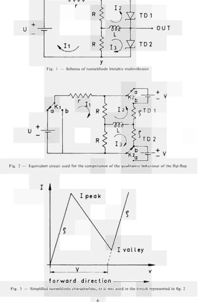
Fig. 3 — Simplified tunneldiode characteristic, as it was used in the circuit represented
in fig. 2 6
Fig. 4 — Equivalent tunneldiode circuit with components drawn in lumped form . . 9 Fig. 5 — Static input characteristic of flip-flop with power supply impedance drawn
as the loadline of the circuit 9 Fig. 6 — Linearisation of the static input characteristic for determination of optimal
bias point 9
Equivalent input impedance of the flip-flop around the bias point . . . . 11
Two cascaded flip-flops with coupling Univibrators 12
Dependence of counting losses from input pulse rate 13
Dependence of counting losses from input pulse rate; as for figure 9 but fast
scaler with 3.5 m[j.s resolution 13 Double-pulse resolution vs. necessary trigger amplitude of the second pulse . 14
Fast tunneldiode discriminator used as input threshold 14 Fig.
Fig.
Fig.
Fig.
Fig.
Fig. 7 8
9
10
11
TUNNELDIODES AS MULTIVIBRATOR FOR FAST COUNTING IN TIME-OF-FLIGHT CODING A N D DERANDOMISING APPLICATIONS
1 — INTRODUCTION
In connection with a time-of-flight coding device under development^), with a minimum channel width of one nanosecond, a fast address scaler with small and stable propagation delay should be realized. The equipment shall be used together with a planned universal data handling system for nuclear experiments, which is under study.
For accurate time determination, the propagation delay jitter of the scaler must be smaller than the minimum channel width, for normal temperature and supply voltage changes.
Transistor flip-flops using current switching, which have propagation delays of about 10 πΐμ5 per stage (*) are here not adequate.
Gated-counters (2) could have very short propagation delays (tunneldiode gates) but their
double-pulse resolution is determined by the used transistor flip-flops and is normally worse than that of a tunneldiode multivibrator.
So a tunneldiode scaler was finally selected to have the possibility of working with a high counting rate. A small propagation delay, which also fer a ten-stage scaler is only slightly longer and practically as stable as that of a gated counter, can be realized.
Collaterally the possible double-pulse resolution of the tunneldiode multivibrator was investigated in order to derandomize spectra with high rates. The use of some cascaded binaries with high double-pulse resolution, connected with a normal slow scaler, can avoid counting losses, by narrowing the pulse distribution around its mean value. For spectra with a great energy range the scale should allow a large amplitude range (dynamic).
In addition a high sensitivity is important to avoid the use of foregoing amplification. As far as possible the device should be insensitive to pulse shape variations.
A definite trigger level would be useful.
2 — TUNNELDIODE MULTIVIBRATOR
The basic multivibrator circuit, as described in the literature (3 and 4) is represented in
figure 1. The supply voltage U is restricted to a magnitude such that one tunneldiode is in the high voltage state and the other in the low voltage state.
The leading edge of the negative (positive) trigger pulse switches the tunneldiode, in the high (low) voltage state, from the high (low) state to the low (high) state. The trailing edge of the trigger pulse switches then the second tunneldiode to the high (low) voltage state, with the help of the memory function of the inductivity L.
2.1 — Equivalent circuit
In order to compute the fundamental dynamic behaviour of the circuit, the equivalent circuit represented in figure 2 is used and negative trigger pulses are chosen.
N
U
" Φ
-
yw w — t
r
R
1 2
J^
TD1
L
O U T
vi^ « J i ¡ ) S "
Fig. 1 — Schema of tunneldiode bistable multivibrator
A W v A
U
Fig. 2 — Equivalent circuit used for the computation of the qualitative behaviour of the flipflop
f o r w a r d
d i r e c t i o n
[image:10.595.138.520.57.495.2] [image:10.595.126.523.144.748.2]Each tunneldiode is replaced here by an equivalent linear circuit consisting of an impedance
ρ and a battery V, switched " on " or " off" by a switch K, according to the voltage state of the tunneldiode.
The tunneldiode characteristic is simplified as represented in figure 3. The tunneldiode in the high voltage state (e.g. TD1) has its switch in the " a " position (Kin serie with ρ) and the tunneldiode in the low voltage state (TD2) has its switch in the " b " position (V off).
The negative trigger pulse should be equivalent to switching U "off" and " o n " by means of the switch K l .
It may be calculated that r (inner impedance of the power supply and trigger generator) has no influence on the dynamic behaviour of the circuit, therefore r shall be neglected in the following mathematical treatment.
In this case (Fig. 2) :
U{R+p) V
h~^lRp 2p ( 1 )
U_ V{R + 2p+pL)
2 2p^ 2p(p + R + 2pL) K¿)
(¿_ V(R + 2pL)
3 2p 2p(R+p + 2pL) w
If the voltage U steps now to zero ( i = 0 ) , the currents decrease in all the branches of the circuit, h decreases below Ivalley (Fig. 3) and the tunneldiode (TD1) jumps down. The switch K2 will then be in the " b " state.
Both tunneldiodes are in the low voltage state. The currents h and h are computed now (all switches in " b " state):
V
f9,.~.m = e-HR+P)/2L (A)
2 ( i"0 ) 2 (R + p) w
This current is positive, which means (Fig. 2) that the tunneldiode (TD1) is backbiased by a current which decreases with a time constant 2L/R+p.
/3
<-
o)
=W^)
e
^
(ñ+p)/2L
(5)
In this case the tunneldiode (TD2) is biased in the forward direction (Fig. 3). Both currents result from the discharge of the inductivity L. When Kl is switched to the " a " state (t=T), and
U steps back to its initial value (end of the trigger pulse) the currents in the two tunneldiodes increase and TD2, which former was in the low voltage state reaches first Ipeak (because of the biasing of h (t>0) and jumps into the high voltage state. The switch K3 is in the " a " state and K2 stays in the " b " state.
If Τ is the time during which U is zero (duration of the trigger pulse), the currents in the tunneldiodes then have following expressions:
'·<'«>= -27 + W T T )
+2W7r
i(Ä+P,/2L(1+ *-«*""">
rø
[/ V(R 4 2ΡΛ V
3 ( i*T ) 2p 2p(p + R) ^2{R+p) K ^ ' y )
2.2 — Practical circuit design for one flip-flop
Foregoing computations are only useful for giving a qualitative idea of the behaviour of the circuit and are not efficient for real components determination. In fact the important regions of the tunneldiode characteristic around Ipeak and Ivalley are not linear at all. Also the assump tion of equal equivalent resistances in both high and low voltage states is at least a factor of two wrong. Further the tunneldiodes were supposed to jump immediately from high to low voltage state and vice versa. The influence of the inner reactive components of the diodes was also neglect ed. These components (Fig. 4) give a lowpass filter characteristic which delays the input pulse action. The actual rise time of the trigger pulse causes also the tunneldiode not to jump imme diately when the trigger pulse appears at the input.
The trigger amplitude was considered to be equal to (J. Practically it is sufficient that the trigger pulse makes h lower than Ivalley.
F is a function of the used semiconductor material (Ge, Si, GaAs), ρ depends on the tunneldiode type and peak current; U, R, r and L are to be chosen.
Since the qualitative formulas give no indications for this, a stable and sensitive bias point is to be determined first. Figure 5 represents the static input characteristic of the flipflop measured between χ and y (Fig. 1).
This curve results from the seriesparallel combination of two tunneldiodes and two resistors (4) and can be calculated by simple superposition.
The bias point will be determined by the power supply impedance considered as the loadline of the system. This loadline must be drawn so that the A state is the only possible static state.
If the voltage is lowered below VB (as for a usual tunneldiode Univibrator) the circuit jumps to the low voltage state. The necessary trigger current is about I A —
IB-If the load resistance is too great, the sensitivity is low and it is possible to have both tunneldiodes in high or low voltage state. With low load resistance a great sensitivity of the tunneldiodes themselves is possible and the static state is well determined, but an important part of the trigger current flows into the power supply circuitry. Hence the load resistor r
(Fig. 1) affects the total sensitivity in two conflicting ways.
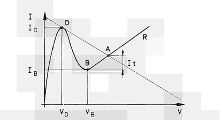
For computing this influence, the characteristic region around the bias point A is consi dered as a straight line (Fig. 6) with angular coefficient R. The trigger current h = I A — I Β can now be calculated as a function of /, R, ID, VD, IB and VB (Fig. 6). The total trigger current
IT, inclusive the trigger losses in r, is:
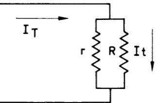
¡τ = h (Fig. 7)
IT = ID — IB VB~ VD
δίτ VB- VD
or + r2
L
Rs
■ΛΛΛΛτ
I d e a l T.D.
Fig. 4 — Equivalent tunneldiode circuit with components drawn in lumped form
Fig. 5 — Static input characteristic of flip-flop with power supply impedance drawn as the loadline of the circuit
[image:13.595.127.424.60.204.2] [image:13.595.97.492.246.442.2] [image:13.595.95.465.491.692.2]When r and U are fixed for optimal sensitivity and stability, R and L will determine the resolution of the flipflop; this means that the time constant 2 L/R-\- g must be chosen great in comparison with the maximum pulse width of the trigger pulses (because of formulas 4, 5) and small in comparison with the shortest time between two trigger pulses (formulas 6, 7).
For a given pulse width, one can say the greater the initial memory current ¡M = V/ρ + R
(4, 5), the smaller could be the time constant. Hence for high counting rates and resolutions, R
must be as small as possible, with a lower limit influenced again by the necessity of having effective negative resistance. When R is chosen, L is given by the necessary memory time constant.
ADDRESS SCALER
3.1 — Circuit details (Fig. 8)
Cascading two or more of these multivibrators presents different problems as for instance undesired coupling between stages through the bias networks. Because of the high duty cycles and fast transients which are possible, only resistive filter elements can be used. But as explained before, the power supply impedance must be low. There is so to be found an optimum compromise between sensitive triggering, best biasing characteristic, small undesired coupling and reasonable power consumption.
Since a flipflop is sensitive to both positive and negative pulses, unipolar trigger pulses must be used. The impedance of elements used to cut away the undesired polarity of pulse must be adapted to the input characteristics of the following flipflop. Therefore ordinary diodes cannot be used; also because the signal levels are to low to give sufficient conduction in the for ward direction. Backward diodes might be used, but better results were obtained with a tunnel diode Univibrator as coupling element between two stages.
This solution gives a quasi complete disappearance of the undesirable polarity of pulse and a regeneration of useful polarity; it permits also to load less the foregoing stage and to trigger the following stage with a greater trigger current.
The increase in propagation delay, with backward diodes as polarity sensitive coupling elements, is smaller than with Univibrators. But the mentioned advantages of Univibrators are predominating for the design.
It may be mentioned that, if a pulse of undesired polarity follows a pulse of the chosen trigger polarity at a distance small enough in relation to the memory time constant of a flipflop no triggering action will be introduced by such pulse. This property may be exploited in certain special cases to avoid polarity sensitive coupling elements.
The spread in the tunneldiode characteristics and in the resistor values causes a spread in the characteristics of the different stages. A trimpot in serie with the filter resistor allows the adjustment of each stage to the same jump down potential (voltage for which the diode in the high voltage state jumps down). Then a greater range of supply voltage, optimum sensitivity and minimum propagation delay is possible.
3.2 — Results
A tenstage address scaler was built and tested. Counting rates :
With 8 mA, short pulses (full width at half maximum (FWHM) about 1.5 ιημβ) counting rates to 200 Megapulses per second (limit of the pulse generator) were tried successfully. With 8 mA peak to peak sine waves, the scaler was tested up to 300 Mc/s.
Dynamic range :
It
Fig. 7 — Equivalent input impedance of the flip-flop around the bias point
The limits of the dynamic range are given theoretically by the width of the pulse at the trigger level. Practically this limit is fixed by the undershoot of the trigger pulse which flops the multivibrator to its initial state. The minimum possible trigger current was about 3 mA. Pulses up to 20 mA were used successfully. (FWHM 1.5 πιμβ).
Voltage stability:
With 8 mA pulses ± 5 % supply voltage changes were allowed for failureless function. Temperature stability:
The scaler was tested with 8 m A pulses between — 15° C and + 55° C and no failure was detected (counting rate: 100 Mc/s).
Propagation delay:
As explained before it was in this case, important to minimize the trigger-propagation delay and especially the jitter of this delay which influences the accuracy of time definition in time coders. The measured delay for the ten-stage scaler was about 16 πιμβ (i.e. 1 πιμβ per flip-flop and 0.6 πιμβ per coupling Univibrator).
The jitter measured at constant voltage and temperature was less than 0.08 πιμβ (resolution of the coincidence unit which was used for this measurement).
Temperature coefficient of delay: — 0.2%o per IoC.
Supply voltage dependence of delay: 2°/0 0 for 1% voltage drift.
Because of the necessary constance of propagation delay the temperature stability of delay was improved by introducing a slightly temperature sensitive power supply voltage.
4 — PULSE DERANDOMISER
4.1 — Statistical design
The regularizing action of fast scales on random pulses was demonstrated in different reports (5). If a slow scaler is preceded by a fast scale of K, the relative counting loss in the slow
scale (6) for small counting losses is given by :
X
=
QK(Nt)
= 1 - J
K ' -Nt(Ntym
Ν : actual counting rate
t : dead time of the slow scaler
These counting losses are reduced by factors much greater than the scaling factors involved if the resolution of the fast scale is good enough.
In figure 9 the dependence of counting losses from the input pulse rate is approximately given for the following conditions :
READ OUT
X
READ OUT
nfr
-vw
*n
VvV— ^ V W - J LJHw*—7
II ^ ^
' '
^"ΑΛΛ/—< -ΛΛ/V-J
%
+
rfr
*M
A
RESET
'^ΛννΗ
■ΛΛΛτ
* RESET
% t o s s e s
[image:17.595.90.432.56.367.2]Rate of random p u l s e s
Fig. 9 — Dependence of counting losses from input pulse rate:
a) for a fast scaler with 2 ι η μ ΐ resolution;
b) for a slow scaler with 1 μ5 resolution, preceded by an ideal scale-of-eight;
b') for the same slow scaler, preceded by an ideal scale-of-ten;
a + b) total losses for the derandomizer system with a scale-of-eight;
a + b') total losses for the derandomizer system with a scale-of-ten.
1
7
-6 1
5
-k
3
2
1
-/ o
I osses
dz
a+b / ' a + b / /
ß I'
A A'»'
i * 1 — ' 1 1 1 —
^ ^ " - a
1 ^
-7
8
M c / s
Rate of r a n d o m p u l s e s
[image:17.595.76.465.80.619.2]mA
θ
7
6
5
-k
3
2
1
-a m p l i t u d e s e c o n d p u l s e
- · ·
-1 1 1 1 1 1 ^ " "
1
2
3
¿
5
6
m/¿s
d i s t a n c e b e t w e e n p u l s e s
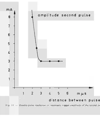
Fig. 1 1 — Doublepulse resolution vs. necessary trigger amplitude of the second pulse
IN ·
\ W
OUT
Fig. 12 — Fast tunneldiode discriminator used as input threshold
[image:18.595.111.488.46.741.2] [image:18.595.154.480.56.437.2]a) A derandomizer with three flip-flops (scale-of-eight) and the best double-pulse reso lution reached (2 πΐμβ);
b) A scale-of-eight with no counting losses followed by a slow scaler with 1 μββϋ reso lution ;
c) The sum of (a) and (b) which gives approximately the counting losses of the derando mizer scaler system.
It follows that for allowable counting losses of 1 %, the counting rate can be 2.5 Mc/s (resp. 3.6 Mc/s for a scale-of-ten). From this results an improvement factor I in maximum pulse rate, that can be given by the expression
«imax. (derandomiser + slow scale) «2Diax. (slow scaler) . scale factor
for fixed counting losses (n max. = max. rate). Optimum values for I are possible with well adapted derandomizerscaler combinations. (For the example: 7 = 3 1 resp. 36, i.e. a scale-of-ten will be better than a scale-of-eight).
For a double-pulse resolution of 3.5 πιμβ (derandomizer with threshold in the input) a scale-of-eight is more optimal as can be seen from figure 10 (7=28.7 resp. 26).
4.2 — Double-pulse resolution
The best double-pulse resolution of 2 n^sec was measured with 8 mA clipped pulses (rise time: 0.5 πΐμε; full width at half maximum (FWHM): 0.8 πιμβ).
Figure 11 gives the minimum triggering amplitude of the second pulse, in function of the delay between the two pulses. The first pulse was kept to a constant value of 3 mA (3 mA = minimum trigger value). After 3 ιημβ all the influences of the preceding switching seem to have vanished.
It was noted that, if a third pulse follows a 2 πιμβ spaced twin pulse (amplitude 8 mA) the third pulse must follow at least 6 πιμ5 after the second one for accurate triggering. This increases theoretically the counting losses. The amount of this loss however is negligible in comparison with the pulse losses due to pulses occurring during the normal 2 ιημ5 dead time of the flip-flop; e.g. with 2 Mc/s random pulses is the ratio about 104.
4.3 — Pulse shape influence
For the moment good pulse sources to utilize the maximum performance of this circuit are not available. The practical limits are mostly given by the trigger pulse shape.
On account of computation of this shape influence on the real resolution of the circuit, two principles should be observed :
The pulse width at the trigger level must be less than 5 πιμβ; if not, the stored information is lost. Enlarging L may increase this maximum storage time but reduces the resolution;
Resolution must be measured on trigger level. Pile-up effects make the pulses merge in each other, and on trigger level the pulses are much nearer than on peak level. (Distance between trailing edge of the first pulse and leading edge of the second one, instead of peak to peak distance). The pulse form is also partially responsible for the sharp rising slope of the curve in figure 10 (distances measured from peak to peak).
Because of this predominating influence of pulse shape, no absolute double-pulse resolution definition can be given. For each case the pulse shape influence must be taken into account sepa rately, i.e. the multivibrator has a theoretical possible resolution better than practical pulses will allow. This resolution is not very much higher than the switching time of the tunneldiodes (smaller than one nanosecond today).
4.4 — Input discriminator
The first binary can itself serve as a discriminator. But because of the possible differences between the two stable states, the accuracy of the discriminating action is not very good. So in most cases a good foregoing discriminator should be useful. Such unit could also avoid spurious triggering by pulses of wrong polarity, and undershoot effects. A higher sensitivity is possible and the flip-flop may be triggered with narrow, fast pulses of about constant amplitude if a tunneldiode Univibrator is taken for discrimination.
However the double-pulse resolution of such discriminator is normally worse than that of the flip-flop, and the resolution of the whole system is reduced.
With the circuit of figure 12 the obtained double-pulse resolution was 3.5 ηΐμβ, but the sensitivity is increased by a factor five at least.
This resolution can still be improved by the use of low-inductivity backward diodes and special circuit lay-out.
5 — CONCLUSION
The limits of tunneldiode multivibrators are not yet reached. The use of faster tunneldiodes, higher peak currents, practically lower inductivities and, also inforced, narrower pulses could allow much higher counting rates.
An important improvement of the circuit would be the use of a non-linear memory element to sharpen the exponential drop of the memory current.
For very short propagation delays, a gated tunneldiode counter should allow delays around 1 ηΐμβ; but the bipolar characteristic of the tunneldiode may cause some difficulties.
Anyhow for much faster circuitry good lumped elements, to use with the low impedance levels of fast tunneldiodes, will be difficult to realize and power consumption risks also to rise quickly.
BIBLIOGRAPHY
1. H. YOURKE "Millimicrosecond Transistor Current Switching Circuit"; IRE transactions on circuit theory,
September 1957.
2. Eldorado S-99 "100 Mc/s Gated Counter". 3. General Electric Tunneldiode Manual, 5.4, p. 54.
4. I.W. JANNEY, Tunneldiodes applications to logic and pulse circuits, Section V, Technical memorandum. 5. A.W. PRYOR and A.G. KLEIN, " Statistical design basis for fast scaling systems ", Nuclear Instruments and Methods,
January, 4 (1959) 2.
6. J. SANDSTAD "Regularizing action of scalers" Nuclear Instruments and Methods, 4 (1959) 243.