www.adv-radio-sci.net/11/137/2013/ doi:10.5194/ars-11-137-2013
© Author(s) 2013. CC Attribution 3.0 License.
Radio Science
A code-aided synchronization IP core for iterative channel decoders
I. Ali, U. Wasenm ¨uller, and N. Wehn
Microelectronic Systems Design Research Group, University of Kaiserslautern, 67663 Kaiserslautern, Germany
Correspondence to: I. Ali ([email protected])
Abstract. Synchronization and channel decoding are integral parts of each receiver in wireless communication systems. The task of synchronization is the estimation of the general unknown parameters of phase, frequency and timing offset as well as correction of the received symbol sequence accord-ing to the estimated parameters. The synchronized symbol sequence serves as input for the channel decoder. Advanced channel decoders are able to operate at very low signal-to-noise ratios (SNR). For small values of SNR, the parame-ter estimation suffers from increased noise and impacts the communication performance. To improve the synchroniza-tion quality and thus decoder performance, the synchronizers are integrated into the iterative decoding structure. Interme-diate results of the channel decoder after each iteration are used to improve the synchronization. This approach is re-ferred to as code-aided (CA) synchronization or turbo syn-chronization.
A number of CA synchronization algorithms have already been published but there is no publication so far on a generic hardware implementation of the CA synchronization. There-fore we present an algorithm which can be implemented effi-ciently in hardware and demonstrate its communication per-formance. Furthermore we present a high throughput, flexi-ble, area and power efficient code-aided synchronization IP core for various satellite communication standards. The core is synthesized for 65 nm low power CMOS technology. Af-ter placement and routing the core has an area of 0.194mm2, throughput of 207 Msymbols/s and consumes 41.4 mW at 300 MHz clock frequency. The architecture is designed in such a way that it does not affect throughput of the system.
1 Introduction
Turbo and low-density parity-check (LDPC) codes are two most popular iterative channel codes nowadays. Due to their impressive communication performance near the Shannon limit they have become part of a wide range of wireless
com-munication standards. As compared to non-iterative codes, they are capable of achieving a certain frame error rate (FER) at significantly reduced signal-to-noise ratios (SNR). How-ever the performance of the iterative codes implicitly as-sumes ideal synchronization of the received signal. Small frequency and phase offsets result in a severe loss of commu-nication performance in these decoders as stated in Mengali and D’Andrea (1997).
During the last decades, communication systems usually were operated at fairly high SNRs and synchronization was not a major source of communication performance degrada-tion of a system as there are many well-established synchro-nization algorithms which can properly synchronize the sys-tems at high SNR. Such synchronizers carry out estimation and correction of channel parameters prior to the decoding and function in either data-aided or non-data-aided modes. As mentioned earlier, Turbo and LDPC decoders can oper-ate at low SNR. Consequently, the channel parameters esti-mation suffers from increased noise at low SNR which de-grades the communication performance of the decoders. To achieve sufficient parameter estimations with these conven-tional synchronizers the amount of known data symbols i.e. pilot symbols had to be increased, which would result in a waste of bandwidth. Therefore in new family of synchroniz-ers, the synchronization is integrated into the iterative decod-ing structure.
Carrier phase, frequency and symbol timing of the re-ceived signal are three primary channel parameters. For pa-rameter estimation and decoding the received signal must be down-converted to the baseband. Due to a slight difference of the oscillators frequencies in transmitter or receiver, a fre-quency offset will arise. Furthermore a frefre-quency offset can appear by the Doppler effect if the transmitter and the re-ceiver are in motion. Origin of the phase offset is given by the unknown transmission delay from the transmitter to the receiver which results in a random phase offset in the re-ceiver. This paper concentrates on the frequency and phase offset estimation and correction (carrier synchronization) for turbo decoding.
At present iterative codes are part of various satellite communication standards like Digital Video Broadcasting – Return Channel via Satellite (DVB-RCS), Digital Video Broadcasting – Satellite services to Handhelds (DVB-SH) and GEO-Mobile Radio Interface (GMR-1 3G). These stan-dards propose best combination of evolved data processing schemes at the transmitter to protect data from destructive channel effects under different transmission conditions and to support high data rate communication. While translating these requirements on the physical layer of a radio terminal, a flexible and high throughput hardware platform is highly desirable. The same hardware architecture should be able to be configured to the required air interface and also be able to accommodate future modifications of the standards.
1.1 State of the Art
A number of code-aided synchronization algorithms based on Expectation-Maximization (EM), the Newton-Raphson (NR), the Steepest-Descent (SD), the factor-graph repre-sentation and the sum-product for implementation of EM, NR and SD, pseudo-maximum-likelihood, and the correla-tion are proposed by different authors Godtmann and Meyr (2006), Herzet et al. (2007), Noels et al. (2005), Lottici and Luise (2004) and Wasenm¨uller et al. (2010). But no generic and flexible hardware implementation of the code-aided syn-chronization is published so far according to the best of our knowledge. This motivates us to introduce an algorithm which can be implemented efficiently in hardware and fur-thermore design a generic, high throughput, and flexible ar-chitecture for the code-aided synchronization to accommo-date multiple wireless communication standards.
1.2 New contributions
This paper has three main contributions: (1) we demonstrate communication performance of a code-aided synchroniza-tion algorithm under different transmission parameters (2) we investigate the impact on throughput and communication performance by running the decoder and the code-aided syn-chronization algorithm in serial and parallel (3) we imple-ment a CMOS synthesis based code-aided synchronization
IP core to accomplish throughput, flexibility and energy effi-ciency requirements of various satellite communication stan-dards. To the best of our knowledge we are the first to publish such an IP core.
This paper is structured as follows. Section 2 introduces turbo codes while Sect. 3 explains code-aided synchroniza-tion principle. In order to illustrate the advantages in com-munication performance due to the code-aided synchroniza-tion, simulation results are presented in Sect. 4. The hardware architecture and its implementation results are described in Sect. 5 and conclusions of this work are given in Sect. 6.
2 Turbo codes
With the introduction of binary turbo codes by Berrou in 1993 Berrou et al. (1993) near optimum error correction be-came possible. Due to these error correction capabilities, bi-nary and duo-bibi-nary turbo codes allow for low frame error rates (FER) at a low signal-to-noise ratio (SNR). Turbo codes generally consist of a serial or parallel concatenation of two codes, so called component codes, and an interleaver.
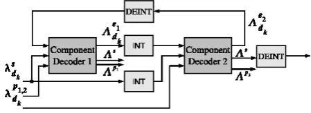
Decoding of turbo codes is an iterative process where probabilistic information is exchanged between component decoders. A possible realization of a decoder for turbo codes is given in Fig. 1. The two component decoders that decode the two component codes are connected via interleaver and deinterleaver. They use log likelihood ratios (LLR)λsd
k,λ p1 dk
andλpd2
k of the systematic and parity information to compute
the extrinsic information 3ed1
k and 3
e2
dk on the information
bits. The iterative exchange of3ed1
k and3
e2
dk between these
component decoders is referred to as turbo principle. One (full) iteration is done if Decoder 1 and Decoder 2 have run once. If only one decoder has calculated new information, we call this one half iteration.
The decoding algorithm consists of a forward and a back-ward recursion. It computes for each possible information or parity bit dk an a posteriori probability (APP) LLR:
3s, 3p1, 3p2.
3 Code-aided synchronization
The synchronization consists of the estimation of the un-known parameters of timing, frequency and phase offset, and the elimination of all possible negative influences introduced by these parameters. We focus on the frequency and phase synchronization in conjunction with turbo decoding. We as-sume, that the steps of gain control, timing synchronization, frame detection and coarse synchronization are properly car-ried out before. The received sample sequencer is given in the complex baseband according to Eq. (1):
Fig. 1. Turbo Decoder.
The sample sequencer withLelements is based on modu-lation symbolss(l)with one sample per symbol and symbol durationT, and is disturbed by a noise sequencen.
The unknown parameters of frequency offsetfoand phase
offset8have to be estimated for every received sample se-quence. These parameters are considered fixed during an es-timation interval; the sample sequence has to be corrected accordingly to the estimated frequency offset f˜o and
esti-mated phase offset 8˜. The synchronization is done in two main steps. Initially, a (coarse) carrier synchronization is per-formed with the help of pilot symbols. Afterwards fine syn-chronization is done iteratively with the additional use of ten-tative decoder decisions after each decoder iteration which is called here code-aided (CA) synchronization. This principle improves the estimation parameters for synchronization. The improved carrier synchronization is used to provide better input data for the decoding process. This process is done it-eratively after each decoder iteration. Frequency and phase offset can be optimally estimated on an unmodulated carrier. With the assumption, that the transmitted symbol sequence sof the burst is known the effect of the modulation by each transmitted symbols(l)can be removed by:
˜
r(l)=r(l)·s∗(l) l=0,1, . . . , L−1 (2) However it must be considered, that usually the symbols of the burst are unknown or only some symbols, used for sup-porting the burst detection or supsup-porting the coarse synchro-nization are known. Thus we replace the transmitted symbol sequencesby an estimated symbol sequencese. The
estima-tion of the transmitted symbol sequence is provided by the turbo decoder. The code-aided estimation of frequency and phase offset is based on the average phaseZ˜0of the front part and on the average phaseZ˜1of the rear part of the burst with a modulation removal by the estimated symbol sequencese.
This is formally given by:
˜ Zk=
L/2−1+k·L/2
X
l=0+k·L/2
r(l)·s∗e(l) k=0,1 (3)
With the two phase values of Eq. (3) the estimate of the fre-quency offset can be calculated with:
˜ f0=
arg(Z˜0· ˜Z1∗)
2π·L (4)
The estimate of the phase offset is calculated with the help of Eq. (4):
˜
φ=arg(Z˜0+ ˜Z1)−L· ˜f0·π (5)
The first decoder iteration is based on the LLR valuesλsd
k,
λpd1
k andλ
p2
dk calculated with the symbols of the coarse
syn-chronized received sequence. For the code-aided synchro-nization an estimate of the transmitted symbols is used, which is produced by the turbo code decoder after each it-eration. The estimate of the transmitted symbols is gathered by the APP LLR of the decoder. A turbo code decoder com-putes APP LLR values3s of the systematic bits by default. In code-aided synchronization applications the decoder must additionally calculate the APP LLR values3p1,2for the par-ity bits. With the tentative soft values of systematic bits and parity bits the sequence se is generated and the described
code-aided synchronization process can be carried out. The LLR are converted into symbols according to the Eq. (6):
se(l)=tanh(
τx(2l)
2 )+jtanh(
τx(2l+1)
2 )
l=0,1, . . . , L−1 (6) Here τx respresents the sequence of τs, τp1 and τp2, which corresponds to the transmitted symbols sequence r. The received sequenceris corrected with the new estimates of frequency and phase offset. The symbols correction is per-formed according to the Eq. (7):
r(l)=r(l)·e−j (2πf˜ol+ ˜8) l=0,1, . . . , L−1 (7)
In this way a new synchronized received sequencer∗is cal-culated after each full decoder iteration. The above presented code-aided synchronization algorithm is very similar to that presented in Luise and Reggiannini (1995) and Wasenm¨uller et al. (2010).
4 Communication performance simulations
0 1 2 3 4 5 6 7 8 9 10 10−5
10−4
10−3 10−2 10−1
100
SNR − Eb/N0 (dB)
FER
info bits 96; code rates (CR) 1/3 and 6/7; iter. no. 8
perfect sync. CR 1/3 with CA sync. CR 1/3 without CA sync. CR 1/3 perfect sync. CR 6/7 with CA sync. CR 6/7 without CA sync. CR 6/7
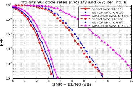
Fig. 2. Performance comparison, with and without CA Sync., short
block length, in presence of residual phase and frequency offset.
each symbols of a block. So we calculated the constant fre-quency offset value for each block depending on its length. The first symbol of the block gets a rotation of−22.5◦then the offset linearly increases for each symbol in a block and the middle symbol gets 0◦phase offset and the last symbol gets a phase offset of 22.5◦. If the input symbols are rotated with an offset of±45◦with QPSK modulation then the de-coder can not decode the data that’s why in all experiments we kept the offset within the limit (±45◦). To get each result 250 000 blocks were simulated.
We used an 8-state duo-binary turbo decoder in our sim-ulations having Max-Log-Map with ESF (extrinsic scaling factor) algorithm having value 0.75, sliding window with one trellis stage, next iteration initialization (NII) acquisition, the window length equal to the information bits, 8 iterations, 6 bit quantization for the input LLR and 7 bit for the extrinsic LLR.
We present frame error rate (FER) graphs to show the im-pact on communication performance of different parameters: frequency offset, phase offset, block length and code rate. Moreover, the effect on communication performance by run-ning the synchronization in parallel to the decoder is also shown.
4.1 Phase and frequency offsets impact
Figures 2 and 3 show the performance of the decoder in pres-ence of residual phase and frequency offsets. FER curves with ideal synchronization i.e. zero phase and frequency off-set, with and without the CA synchronization are also shown in the figures. It is evident that the residual phase and fre-quency offsets degrade the decoder performance but the CA synchronization significantly improves the performance, i.e. the communication performance is close to the ideal synchro-nization by doing CA synchrosynchro-nization.
0 1 2 3 4 5 6 7 8
10−4
10−3
10−2
10−1
100
SNR − Eb/N0 (dB)
FER
info bits 1728; code rates (CR) 1/3 and 6/7; iter. no. 8
perfect sync. CR 1/3 with CA sync. CR 1/3 without CA sync. CR 1/3 perfect sync. CR 6/7 with CA sync. CR 6/7 without CA sync. CR 6/7
Fig. 3. Performance comparison, with and without CA Sync., long
block length, in presence of residual phase and frequency offset.
4.2 Block length and code rate variations
We carried out simulations with different block lenghts and code rates in presence of residual phase and frequency off-sets. In this paper, we present the communication perfor-mance of the CA synchronization with the shortest and the longest block lengths and, the lowest and the highest code rates of DVB-RCS standard. The Figs. 2 and 3 show the re-sults with 96 and 1728 bits block lengths and, 1/3 and 6/7 code rates. The gain in communication performance due to CA synchronization depends upon code rate, block length, and residual phase and frequency offset. The figures show that at FER 10−3 the performance gain is almost 0.25 dB with code rate 1/3 and almost 1.6–2.0 dB with code rate 6/7 depending upon the block length.
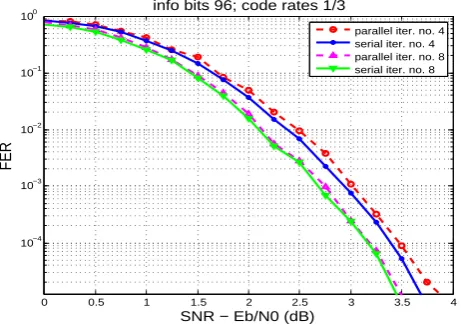
4.3 Synchronization running in parallel impact
0 0.5 1 1.5 2 2.5 3 3.5 4
10−4
10−3
10−2
10−1
100
SNR − Eb/N0 (dB)
FER
info bits 96; code rates 1/3
parallel iter. no. 4 serial iter. no. 4 parallel iter. no. 8 serial iter. no. 8
Fig. 4. Performance comparison, CA Sync. running in serial and
parallel with the decoder.
5 Architecture and its implementation
The architecture of the system is shown in Fig. 5. We use synthesizable VHDL for modeling and implementing the ar-chitecture. The modules shown with dotted box in the figure, demapper and decoder, are not part of the architecture and are shown here just for architecture operation explanation. We use Lookup Tables (LUTs) to store the values of tanh, sin and cos which are required to convert the input LLR into symbols and for the symbols correction. We use STMicro-electronics ROMs for implementing all the LUTs and a DPR (dual port ram) 3072×20 to store the symbols. Two complex MAC (Multiply-Accumulate) units are implemented to per-form the correlation and correction functions in parallel. Sec-ond term of Eq. (5) is also mapped on the correlation MAC unit to save an additional multiplier. Moreover a divider is implemented to get the frequency offset as described in Eq. (4).
5.1 LUT based phase calculation
We use a LUT for phase calculation (Eq. (4) and Eq. (5)) instead of using a full CORDIC (Coordinate Rotation Digi-tal Computer). The address of the LUT is generated by the correlation function. However, the output of the correlation function is a complex number having large bitwidth. So it is required to reduce the bitwidth of the number in order to re-duce the LUT size. Instead of directly truncating LSBs of a complex number which can result a number with less infor-mation carrying bits, we do scaling in a smart way. So first we truncate all possible no information carrying MSBs and then the complex number is shortened and rounded to 10 bits. 5.2 Operation
After one iteration of the turbo decoder, LLRs of the system-atic and parity bits are available at the output of the decoder.
LLR to
symbols Correlation
LUT based angle calculation
Dual Port
RAM correction Ø & ƒ registers Offsets Input LLR
Input symbols
Demapper Decoder
Fig. 5. Architecture of the code-aided synchronization.
Two LLR values are transferred to the “LLR to symbols” module in one clock cycle to convert them into a symbol for QPSK modulation for implementation of Eq. (6). The sym-bols received by the AWGN channel are stored into the DPR. One symbol from the DPR and the soft symbol at the output of the “LLR to symbols” module are transferred to the “Cor-relation” module. One symbol is processed in one clock cycle and in this way the whole block is processed.
The “Correlation” module implements Eq. (3) and its re-sult is transferred to the “LUT based angle calculation” mod-ule for computation of angles (see argument function in Eq. (4) and Eq. (5)). The “Offsets registers” module saves the re-sults of Eq. (4) and Eq. (5) for current iteration. The “Ø &f correction” module implements Eq. (7).
5.3 Synchronization running in parallel to decoder
To run the synchronizer in parallel to the decoder, the phase & frequency (Ø &f) correction module remains idle during the first decoder iteration. When the decoder executes its sec-ond iteration and the LLR are available at its output and then the correlation and correction modules start their operations in parallel. A symbol is read from the DPR and it is trans-ferred to both the correlation and correction modules, in the same clock cycle. In this way we save a lot of accesses to the DPR. So the correlation is performed on the decoder (n+ 1)-th iteration output while 1)-the correction is performed on 1)-the decodern-th iteration output. One symbol is corrected in one clock cycle and it is saved into the DPR again. So the DPR is used to save the corrected symbols also. After correction of a complete block, it is transferred to the demapper for next iteration of the decoder.
5.4 Implementation results
Table 1. Post-layout area results.
Component Case Max. clock freq. Area
DPR Worst 300 MHz 0.089 mm2
Logic Worst 300 MHz 0.041 mm2
ROMs (LUTs) Worst 300 MHz 0.064 mm2
Sum 0.194 mm2
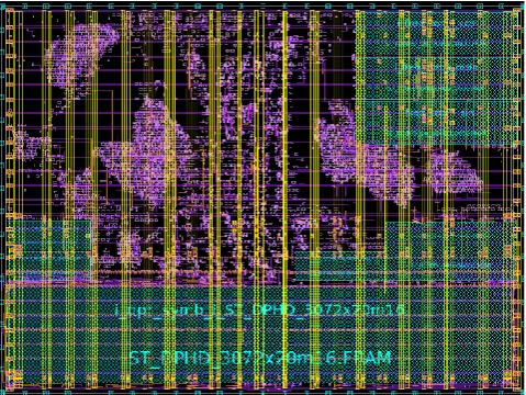
following process, voltage and temperature (PVT) parame-ters: Worst Case (WC, 1.1V, 125◦C), Nominal Case (NOM, 1.2V, 25◦C) and Best Case (BC, 1.3V, −40◦C). Synthe-sis was performed with Synopsys Design Compiler in to-pographical mode, placement and routing (P&R) with Syn-opses IC Compiler. The DPR can operate at maximum 300 MHz clock frequency so we synthesized the core at this frequency. Table 1 shows the results for area and the final physical design is shown in Fig. 6. We calculated the power consumption of the physical design with Syn-opsys PrimeTime-PX. The design consumes 51.0, 41.4 and 35.4 mW at best, nominal and worst case, respectively, at 300 MHz clock frequency.
The synthesis results show that we save a significant area by using a LUT for phase calculation. It occupies only 0.0186 mm2 area while a complete CORDIC implemented on a 65 nm ASIC takes 0.86 mm2area Qi et al. (2010). How-ever the CORDIC can also perform sHow-everal other functions like conversions between polar and rectangular coordinates. 5.5 Flexibility
We analyzed requirements for utilizing the IP core for differ-ent satellite communication standards like RCS, DVB-SH, and GMR-1 3G and to support these standards we pro-vided flexibility in the architecture at: (i) run time – block length and modulation scheme (ii) design time – bitwidths of the input symbols, the decoder LLR, and the intermediate results, and maximum number of iterations.
5.6 Throughput
The architecture has a throughput of 207 Msamples/sec for one iteration. This calculation includes both systematic and parity bits after depuncturing a block. This throughput is suf-ficient to meet various satellite communication standards re-quirements.
6 Conclusions
The code-aided synchronization improves the communica-tion performance of the iterative decoders with a gain of 0.25 to 2.0 dB at FER 10−3depending on block length, code rate, and residual phase and frequency offset. In this paper, we presented, to the best of our knowledge, the first published IP
Fig. 6. Physical design including the DPR.
core for the code-aided synchronization. The core functions in parallel to the decoder so it does not degrade its through-put.
References
Berrou, C., Glavieux, A., and Thitimajshima, P.: Near Shannon Limit Error-Correcting Coding and Decoding: Turbo-Codes, in: Proc. 1993 International Conference on Communications (ICC ’93), 1064–1070, Geneva, Switzerland, 1993.
Herzet, C., Noels, N., Lottici, V., Wymeersch, H., Luise, M., Moeneclaey, M., and Vandendorpe, L.: Code-Aided Turbo Syn-chronization, Proceedings of the IEEE, 95, 1255–1271, 2007. Lottici, V. and Luise, M.: Embedding Carrier Phase Recovery Into
Iterative Decoding of Turbo-Coded Linear Modulations, IEEE Transactions on Communications, 52, 661–669, 2004.
Luise, M. and Reggiannini, R.: Carrier frequency recovery in all-digital modems for burst-mode transmissions, Communications, IEEE Transactions on, 43, 1169–1178, 1995.
Mengali, U. and D’Andrea, A.: Synchronization Techniques for Digital Receivers, Plenum Publishing Corporation, New York, 1997.
Noels, N., Lottici, V., Dejonghe, A., Steendam, H., Moeneclaey, M., Luise, M., and Vandendorpe, L.: A Theoretical Framework for Soft-Information-Based Synchronization in Iterative (Turbo) Receivers, EURASIP J. Wireless Comm. and Networking, 2005, 117–129, 2005.
Qi, Z., Cabe, A., Jones, R., and Stan, M.: CORDIC implemen-tation with parameterizable ASIC/SoC flow, in: IEEE South-eastCon 2010 (SouthSouth-eastCon), Proceedings of the, 13–16, doi:10.1109/SECON.2010.5453930, 2010.
Godtmann, S., Hadaschik, N., Steinert, W., Pollok, A., Ascheid, G., and Meyr, H.: Coarse and Turbo Synchronization: A Case-Study for DVB-RCS, in: NEWCOM-ACoRN Workshop, Vienna, Aus-tria, 2006.