Printed in The Islamic Republic of Iran, 2006 © Shiraz University
ANALYSIS AND CONTROL OF VOLTAGE HARMONICS GENERATED
BY THYRISTOR CONTROLLED SERIES CAPACITORS
*A. KAZEMI
**, S. M. MOUSAVI BADEJANI AND M. A. S. MASOUM
Center of Excellence for Power System Automation and Operation, Dept. of Electrical Engineering, Iran University of Science & Technology, Tehran, I. R. of Iran
Email: [email protected]
Abstract– This paper analyzes the harmonic performance of thyristor controlled series capacitors
(TCSCs) in power systems and proposes an effective method for their control and limitation in the compensated line. This is performed by proper selection of TCSC elements (capacitance and inductance) and by introducing a new method for adjusting its firing angle such that high line loadability as well as low harmonics generation is achieved. Finally, a TCSC is designed, modeled, simulated and analyzed. The main contribution is the consideration of power quality phenomena, as well as loadability in the TCSC control scheme.
Keywords – TCSC, harmonics, firing angle and loadability
1. INTRODUCTION
Thyristor controlled series capacitor (TCSC) provides continuously variable capacitance by controlling the firing angle. TCSCs have many benefits for AC transmission systems such as improved efficiency [1], controlled power flow [2], enhanced transient stability [3], improved power quality [4] and power transfer capability, as well as damping sub-synchronous resonances [5]. To achieve these advantages, proper schemes for controlling TCSC firing angles are required. Several strategies have been proposed and used for controlling TCSC in power system utilities [6].
The main drawbacks of TCSC are the nonlinear effects on system stability, discrete (non-continuous) impedance and harmonics injection. It is known that harmonic currents and the resulting harmonic voltages can be magnified considerably causing all sorts of operational problems, especially if a resonance occurs at one of the harmonic frequencies. For this reason, a recommended limit of 1% for each harmonic voltage is set and used in power systems above 138 kV [7]. In compensated transmission lines using TCSC, harmonic currents and voltages depend on the size and location of the compensator [2]. Therefore, it is important to consider the harmonic performance when designing TCSCs.
In this paper, line loadability in the presence of TCSC is presented. Voltage harmonics of TCSC versus line current as a function of its firing angle are computed and analyzed. MATLAB facilities are used to simulate a sample system with a designed TCSC. Several case studies are used to demonstrate the impact of the firing angle on overall system power quality. Finally, an adaptive control scheme is proposed for TCSC that considers conventional (e.g., loadability) and power quality issues.
2. TCSC BASIC THEORY
The basic configuration of TCSC makes use of a fixed capacitor in parallel with a thyristor controlled reactance (TCR) as shown in Fig. 1.
In order to simulate the performance of TCSC and illustrate its effects on transmission line loadability and power quality, the 345 kV, 382 km line located in the southwest region of the United States is considered [2]. System diagram and line parameters are illustrated in Fig. 2 and Table 1. The main purpose of using
TCSC is to reach the maximum power transfer ( 1
. L Max
P ) of the transmission line (e.g., 100% compensated).
Fig. 2. The 345 kV, 382 km line (located in the southwest region of the United States [2]) used for simulations
The quotient between the resonance frequency of TCSC (ωr =1 LC ) and the network frequency (ω) is
L C
r = X X
=
ω ω
λ (1)
where
X
C and XL are bank capacitance and thyristor branch reactance, respectively. The fundamentalcomponent of TCSC voltage [8] is used to measure the equivalent device impedance )) 2 tan( ) 2 tan( ( ) 1 ( ) 2 ( cos 4 )) sin( ( 1 2 2 1
1 λ λδ δ
λ ωπ δ δ δ ωπ
ω + + − − −
− = ≡ K C K C I V X line (2)
where, K =ωr2 (ωr2 −ω2).
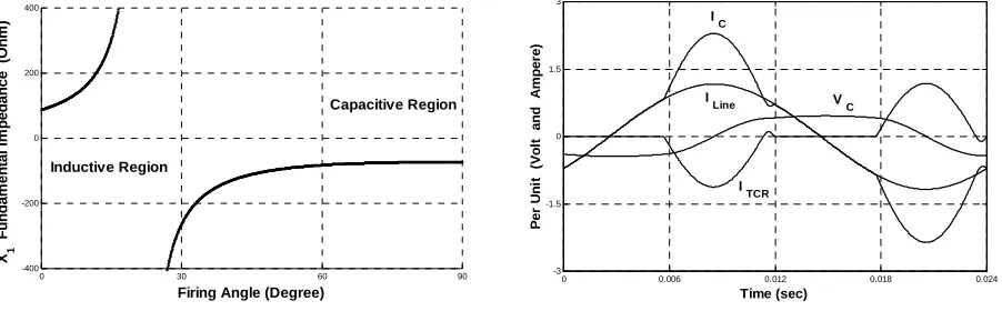
Figure 3 shows the fundamental impedance of TCSC as a function of its firing angleα.
Table 1. Transmission line parameters for the 345 kV, 382 km line (Fig. 2) located in the southwest region of the United States [2]
z (series impedance) .027+j.375[Ωkm]
y (shunt admittance) j4.273[µΩ.km]
C
I (current carrying capacity) 1050 [A]
SIL (surge impedance loading) 400 [MW] .
Max
P (practical line loadability) 460 [MW](≈1.15pu)
1 .
L Max
P (thermal limit) 625 MW](≈1.5pu) 2
.
L Max
P (theoretical limit) 790 [MW] (≈2pu)
G
TCSC L Line2 191 km Line1191 km
MOV C L line I MOV I C I TCR I
Fig.1. Basic circuit of TCSC (C: fixed series capacitor, L: thyristor controlled inductance, MOV: Metal
Generally, a TCSC is controlled by varying the firing angle, measured from the zero crossing of line current or capacitor voltage waveforms. Among published papers, two definitions for the reference
waveform of firing angle are presented [9-10]. The relation between α and δ (TCR conduction angle) for
these cases are
π δ α + =
2 (3)
2 2
π δ
α+ = (4)
Equations (3) and (4) are used when α is adjusted based on the capacitor voltage (e.g., measured from
zero crossing of the capacitor voltage) and the line current (e.g., measured from zero crossing of the line current), respectively.
In Eq. (2), the conduction angle δ is always less than π , therefore this equation becomes infinitely large when the conduction angle is equal to δr (e.g., cos(λδr 2)=0). At this angle, resonance occurs in the TCSC and its fundamental impedance will be unlimited. For δ <δr (α >αr) fundamental impedance of TCSC (X1) will be negative (e.g., the capacitive region in Fig. 3) and for δ >δr (α <αr), X1 will be positive (e.g., the inductive region in Fig. 3).
Figure 4 demonstrates the electrical parameters of a TCSC in the capacitive region. The equivalent capacitor of this region is [5]
L
C
C
(
)
sin(
2)
πω
δ
δ
δ
=
−
−
(5)Equation (5) illustrates the equivalent capacitive reactance of the TCSC due to the firing effect of TCR with conducting angleδ.
3. ANALYSIS OF TCSC HARMONICS
Following the same methodology as used in Eq. (2), for the fundamental coefficient of the TCSC voltage, the ratio of harmonic voltages to line current is
) (
) (
δ δ
Den Num I
V
line
n = (6)
where
0 0.006 0.012 0.018 0.024
-3 -1.5 0 1.5 3
Time (sec)
P
e
r U
n
it
(
V
ol
t
a
n
d
A
m
pe
re
)
I
Line
I
C
I
TCR
V
C
Fig. 4. Electrical parameters of TCSC
0 30 60 90
-400 -200 0 200 400
Inductive Region
Firing Angle (Degree) X1
Fu
nda
m
e
n
ta
l I
m
peda
nc
e
(O
hm
)
Capacitive Region
)] (
) 2 cos( ) 2 sin( ) )(
2 sin( ) 2 cos( ) 1 ( ) 2 cos( ) 2 [cos( 4
)
(δ = ×ωr2 δ δ ωrω 2 − − δ δ 2ω2−ωr2 − δ δ nωr2−ω2
n n
n n
n Num
and
) )(
)( 1 ( )
( nC n2 r2 2 n2 2 r2
Denδ = πω − ω −ω ω −ω
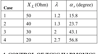
In Eq. (6), the ratio of harmonic voltages to line current depends on the TCSC component values [11]. To demonstrate the impact of TCSC parameters on its harmonic performance, four cases are analyzed. The
main parameters of TCSC are computed for a fixed capacitance of XC =−73Ω (e.g., 50% compensation
of line impedance in TCSC blocking mode), as shown in Table 2. Fig. 5 shows plots of low order harmonic voltages amplitudes versus TCSC firing angle for these four cases.
Table 2. Computed TCSC parameter values for different cases
Case XL(Ohm)
λ
αr(degree)1 50 1.2 15.8
2 40 1.3 23.7
3 30 2 43.1
4 20 2.7 56.8
4. CONTROL OF TCSC HARMONICS
The performance of TCSC is better in the bypass mode [9] for small values of XL. The bypass mode is
utilized as a means to reduce the capacitor stress during fault conditions. In this mode it is better to have a large value for
λ
and smallXL (Table 2). However, from the harmonics point of view, it is better to have a largeXL (Fig. 5).Therefore, in selecting parameter values of TCSC, one must make a compromise between its performance and loadabilty (Table 2) and generated harmonics (Fig. 5).
According to Fig. 5, cases 1 and 2 are better than cases 3 and 4. Also, for improving the performance
of TCSC, it is better to select the smaller value of XL [9] between these two cases. So for the system
under consideration (Fig. 1), selectingXL =40Ω (e.g., case 2 in Table 2) is more appropriate since it
generates fewer harmonics (Fig. 5b) and enjoys a relatively large value of
λ
.Table 3. The sign of the proposed adaptive controller for different firing angle regions
α region controller sign 0-12 [Degree] -1
12-22 [Degree] +1 22-38 [Degree] -1 38-47 [Degree] +1 47-63 [Degree] -1 63-77 [Degree] +1 77-90 [Degree] -1
The maximum compensation of harmonics in this control method is limited by ∆α . This parameter is
achieved by permissible power line changes near the desired value.
Table 4. Maximum value of TCSC Harmonics in case 4 (α=0-90, Degree).
Harmonics order
3 5 7 9 11 13 15 17 19 21
Max (Vn Iline )
1.255 0.216 0.075 0.034 0.018 0.011 0.007 0.005 0.003 0.002
0 30 60 90
-1 -0.5 0 0.5 1
Firing Angle (Degree) n= 3
n= 7 n= 5
0 30 60 90
-1 -0.5 0 0.5 1
Firing Angle (Degree) n= 3 n= 7
n= 5
(a) (b)
0 30 60 90
-1 -0.5 0 0.5 1
Firing Angle (Degree) n= 3
n= 7 n= 5
0 30 60 90
-1 -0.5 0 0.5 1 1.5
Firing Angle (Degree) n= 3
n= 5 n= 7
(c) (d)
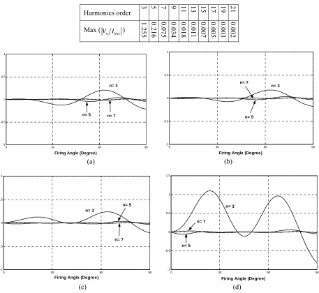
5. SIMULATION RESULTS
Simulink facilities are used to simulate and investigate the harmonic performance of TCSC as shown in Fig. 6. The generator is simulated using the equivalent source-impedance circuit as shown by the "Equivalent Generator" block in Fig. 6a. For simulation of transmission lines (e.g., two 191 km lines of Fig. 1), blocks, "Line 1" and "Line 2" are used. In addition, three measurement blocks are considered for monitoring the electrical parameters of the transmission lines. The main block, called "Series Comp. (TCSC)", simulates the compensation characteristic of TCSC as shown in Fig. 6b. The main part of this figure is the "Switch and Control Block ", which is demonstrated in Fig. 6c.
6. ANALYSIS
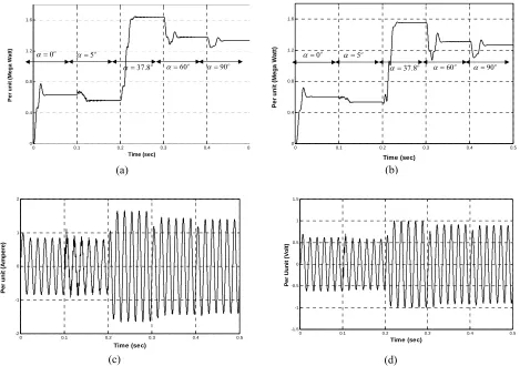
In Fig.7 the electrical parameters of the transmission line are presented for different values of firing angel.
At α =0o and5 , TCSC operates in the inductive region. The capacitive region is obtained at firing o
angles of 37.8o, 60 ando 90 . At o 37.8o, the TCSC compensation level is 100% and the power transmitted
from the line is adjusted for 1.6 per unit (e.g., the thermal limit in Table 2) as shown in Fig. 7a. The difference of Figs. 7a and 7b shows the line power dissipation. In addition, sending current and receiving voltage (per unit) are shown in Figs. 7c and 7d, respectively.
For the firing angles discussed in Fig. 7, the voltage harmonics behavior of TCSC are computed and plotted in Fig. 8. In this figure, the dominated harmonics of TCSC (e.g., the third harmonics) with and
without the proposed adaptive∆α control scheme is shown.
(a)
(b) (c)
Fig. 6. Simulated TCSC system (Fig. 1) and controller: (a) system diagram; (b) details of TCSC block and protection circuit; (c) details of switching and control block
(a) Measurement 1
Measurement 2
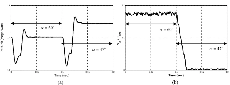
It is interesting to know that for some cases, harmonics controlling does not have any major impact on TCSC main characteristics. This is demonstrated for a selected case in Fig. 9. It is evident that firing angle control for harmonics mitigation has not affected the main functions of TCSC.
Fig. 7. Simulation results: transmission line parameters for different firing angles: (a) sending power; (b) receiving power; (c) sending current; (d) receiving voltage
0 0.1 0.2 0.3 0.4 0
0 0.4 0.8 1.2 1.6 Time (sec) P e r u n it (M e g a W a tt) (a)
0 0.1 0.2 0.3 0.4 0.5
-2 -1 0 1 2 Time (sec) P e r u n it (A m p er e) (c)
0 0.1 0.2 0.3 0.4 0.5
0 0.4 0.8 1.2 1.6 Time (sec) Per u n it (M eg a W a tt) (b)
0 0.1 0.2 0.3 0.4 0.5
-1.5 -1 -0.5 0 0.5 1 1.5 Time (sec) P e r U u n it (V o lt) (d) o 5 = α o 0 = α o 8 . 37 =
α α=60o α=90o
o 5 = α o 0 = α o 8 . 37 =
α α=60o α=90o
0 0.1 0.2 0.3 0.4 0.5
0 0.05 0.1 0.15 0.2 Time (sec) V3 / I lin e
Fig. 8. Simulation results: ratio of third voltage harmonics of TCSC to line current with and without the proposed adaptive ∆
α
controllero 5 = α o 0 = α o 8 . 37 =
α α=60o α=90o
7. CONCLUSION
Harmonic pollutions of TCSCs in compensated transmission lines are investigated. An adaptive firing angle controller capable of limiting TCSC harmonics is proposed. Simulink facilities are used for theoretical analysis and system simulation.
The main conclusions are:
•Harmonic pollutions of TCSC are highly dependent on the firing angle and compensated level (Fig. 5).
•Generated harmonic levels are nonlinear functions of the TCSC component values (Table 2, Fig. 5).
•Decreasing the size of TCSC inductor, rapidly increases the harmonic pollution.
•Harmonic voltages of a TCSC depend on line current (Eq. (6)).
•The proposed adaptive harmonics controller does not have any undesired effects on TCSC
characteristics (Fig. 9).
•Implementation of proposed method is relatively simple (Table 3).
REFERENCES
1. Kimbark, E. W. (1966). Improvements of system stability by switched series capacitors. IEEE Trans. on PAS, 85(2), 180-188.
2. Kingston, R., Holmberg, N., Kotek, J. & Baghzouz, Y. (1994). Series capacitor placement on transmission lines with slightly distorted currents. IEEE Power Eng. Society, Chicago, USA, 221-226.
3. Dolan, P. S., Smith, J. R. & Mittelstand, W. A. (1995). A study of TCSC optimal damping control parameters for different operating conditions. IEEE Tran. on Power System, 10(4), 1972-1978.
4. Tenorio, A. R. M. & Daconti, J. R. (1998). Voltage sag mitigation by means of thyristor controlled series capacitors. IEEE/PEC Athens, Greece Conf., 572-576.
5. Perkins, B. K. & Iravani, M. R. (1997). Dynamic modeling of TCSC with application to SSR analysis. IEEE Tran. on Power System, 12(4), 1619-1626.
6. Escobar, G., Stankovic, A. M., Mattavelli, P. & Ortega, A. (2001). A comparative study of three nonlinear controllers for TCSC. IEEE Power Tec. Conf., Porto, Portugal, 422-423.
7. IEEE Std. 519, (1999) IEEE Recommended Practices and Requirements for Harmonic Control in Electric power systems, IEEE Press.
Fig. 9. Transmitted power and harmonics injection of TCSC with the proposed adaptive controller: (a) transmission line sending power; (b) ratio of
third harmonic voltage of TCSC to line current
0 0.05 0.1 0.15 0.2
1.2 1.4 1.6
Time (sec)
P
e
r
U
n
it (M
e
g
a
W
a
tt
)
(a)
0 0.05 0.1 0.15 0.2
0 0.1 0.2
V3
/
I lin
e
Time (sec)
(b) o
60
=
α
o
47
=
α
o
60
=
α
o
47
=
8. Christl, N., Hedin, R., Sadek, K. & Mckenna, S. M. (1992). Advanced series compensation (ASC) with thyristor controlled impedance. Cigre, Paris, France, 14/37/38-05.
9. Song, Y. H., Johns, A. T., Gazarian, & Warne, D. F. (1999). Flexible AC transmission systems (FACTS)", IEE power and Energy series 30, ISBN 0 85296 7713, british library cataloguing in publication data, 199-222.
10. Leonidaki, E. A., Hatziargyriou, N. D., Papadias, B. C. & Georgantzis, G. J. (1998). Investigation of power system harmonics and SSR phenomena related to thyristor controlled series capacitors. 8 International Conference on Harmonics and Quality of power, Athens, Greece, 0-7803-5105-3/98, 848-852.
![Table 1. Transmission line parameters for the 345 kV, 382 km line (Fig. 2) located in the southwest region of the United States [2]](https://thumb-us.123doks.com/thumbv2/123dok_us/22664.2002465/2.595.194.391.58.199/table-transmission-parameters-located-southwest-region-united-states.webp)