Available online:
https://edupediapublications.org/journals/index.php/IJR/
P a g e | 2048Simulation Analysis of Low Voltage Micro grid under Different Fault
Conditions using Fault Models
P. Pravallika
& M. Madhusudhan Reddy
1M Tech student of Dr KVSRIT, KURNOOL, INDIA.
2Assistant Professor, Department of EEE, KVSRIT, KURNOOL,INDIA.
ABSTRACT
Microgrid, which provides a new and effective way of making full use of distributed energy, still faces numerous technical challenges [1]–[3]. Microgrid protection [4], [5] is one of them. To understand the fault features of microgrid, it is necessary to explore the fault models of IIDGs, which take the dominant position of micro-sources within a microgrid. In essence, IIDGs can be classified into PQ controlled IIDGs (PQ-IIDG) and voltage controlled ones (V/f-IIDG). PQ-IIDG injects a given power into microgrid and acts as a controlled current source. V/f-IIDG is responsible for maintaining the voltage and frequency of microgrid, so it behaves like a controlled voltage source. The key point of developing IIDGs’ fault models is to understand how they respond to abnormal conditions when fault occurs in microgrid, in other words, how their voltage or current references change. In [17], a virtual impedance based method is applied to modify the voltage references of V/f-IIDG, thus to limit the over current caused by load step; however, the cases of unbalanced faults are not taken into consideration.
In this work, develops fault models of IIDGs within a low-voltage microgrid, including active/reactive power (PQ)-controlled IIDGs and voltage-controlled IIDGs. Voltage-controlled IIDG is of great significance on maintaining a stable microgrid. The model of controlled IIDG proposed in this work, keeps its voltage-source nature while accomplishing current limiting. The performance of the proposed IIDG fault models can be implemented in Matlab/Simulink environment.
Keywords— Current limitation, fault model,
inverter-interfaced distributed generator, microgrid.
I. INTRODUCTION
Distributed generation (DG) units, distributed storage (DS) units and integrated distributed generation/storage units constitute the broader family of distributed energy resources (DR). Available and currently
developing technologies for DG and DS units are based on i) combustion engines, micro- and mini-gas-turbines, wind turbines, fuel-cells, solar-thermal systems, photovoltaic systems, low-head hydro units and geothermal systems and ii) battery storage, capacitor storage, low- and high-speed flywheel systems and Superconducting Magnetic Energy Storage (SMES) systems. While only DG units are considered in this thesis, many similarities exist between the operation of DG units and other DR units in terms of system studies. A DG unit may be interfaced to the grid either directly through an AC rotating machine or through a power electronic converter. A unit which utilizes a power electronic conversion system as the interfaced medium provides a higher degree of speed and flexibility to control the output frequency, voltage and real/reactive power of the unit. Deregulation of the electric utility industry, environmental concerns associated with central electric power plants, volatility of electric energy cost, and rapid technological developments of DG systems all support the proliferation of DG units in electric utility systems. Furthermore, the increase in DG penetration depth and the presence of multiple DG units in electrical proximity to one another have brought about the concept of the micro-grid [1], [2]. A micro-micro-grid is formed when an electrical region capable of autonomous operation is islanded from the remainder of the grid; e.g., a distribution substation along with its feeders that service both DG units and local loads. Formation of a micro-grid due to an islanding process can be due to disturbances, such as a fault and its subsequent switching incidents, or due to preplanned switching events. The micro-grid is to remain operational in an autonomous mode after islanding and meet the corresponding load requirements.
Available online:
https://edupediapublications.org/journals/index.php/IJR/
P a g e | 2049[4]. However, to realize the full benefit of high DG penetration depth, the autonomous operation of micro-grids needs to be considered. Clearly, micro-grid operation has a far reaching impact on the existing safety, control, protection and dispatch practices and strategies of electrical energy, yet micro-grid operation has neither been fully understood nor investigated.
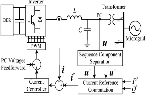
Fig. 1.1 Configuration and control block diagram of PQ-IIDG.
A. Literature Survey
The increase in power demand is stressing the transmission and generation system capabilities, leading to frequent power outages. In USA alone, these frequent power outages due to overloaded grid costs the economy $ 104 to $ 164 billion dollars per year. The central plants are at best 35% efficient due to generation and transmission losses. The greenhouse gas emissions have risen owing to the less efficient power system [1]. This led to increased research aiming to meet the growing energy demand without adding the transmission system capabilities. The use of distributed generation (wind turbines, PV arrays, etc) at the distribution system seems to be a viable solution. But, unplanned application of individual distributed generators, while solving some problems, can cause additional problems [1]. The micro grid concept has the potential to solve major problems arising from large penetration of distributed generation in distribution systems. Micro grids are almost 85% efficient as they have very little transmission losses and use the surplus heat to warm or cool buildings [1]. During power outage or disturbance, micro grids can island themselves and retain power availability, avoiding blackouts and lost productivity.
Sufficient amount of dynamic reactive power capabilities are needed to avoid a fast voltage collapse. In principle, a coordinated effort among the reactive sources could result in better effectiveness of these resources. However, in typical power systems, where the electrical distances between the reactive sources and where these reactive powers are needed are long, a coordinated effort may not be suitable due to the excessive voltage drop resulting from the transfer of reactive power within long distances. That is why, in practice, reactive power compensation is usually coming from local sources. In micro-grids, the electrical distances between the sources of the reactive power and the loads, which need the reactive power compensation, is not much; thus a coordinated compensation of reactive power sources for dynamic voltage stability should be desirable. Several blackouts have been associated with voltage stability problems in a power system [2] [3]. The presence of weak micro grids with insufficient amount of dynamic reactive power capabilities can also cause blackouts in micro grids and consequently the main power system.
II. PROBLEM FORMULATION
Microgrid, which provides a new and effective way of making full use of distributed energy, still faces numerous technical challenges [1]–[3]. Microgrid protection [4], [5] is one of them. A reliable protection system is indispensable to ensure the safe operation of microgrid. Unfortunately, the traditional over current protection is not suitable for microgrid, especially in islanded mode, for its fault characteristics are very different from those of traditional distribution grid. To understand the fault features of microgrid, it is necessary to explore the fault models of IIDGs, which take the dominant position of micro-sources within a microgrid.
Available online:
https://edupediapublications.org/journals/index.php/IJR/
P a g e | 2050functionality for DGs, and some grid codes [7], [8] require that DGs should provide reactive current preferentially. In contrast, Guoet al [9] introduce that supplying active power achieves more effective voltage support in low voltage grid. In [10], Cornelis et al propose that IIDGs inject a pre-defined positive sequence current into grid. References [11]–[15] present various fault control strategies for PQ-IIDGs. And the common feature of these strategies is that IIDGs could feed positive and negative sequence current into grid simultaneously. Zamani et al [16] accomplish the current limiting of V/f-IIDG by compressing its current references without distortion; however, it‘s hard to derive the precise expression of IIDG‘s fault currents. In [17], a virtual impedance based method is applied to modify the voltage references of V/f-IIDG, thus to limit the over current caused by load step; however, the cases of unbalanced faults are not taken into consideration.
Objective of the Thesis
In this thesis, the modeling of a micro grid is presented. In this developed fault models of IIDGs within a low-voltage microgrid, including active/reactive power (PQ)-controlled IIDGs and voltage-controlled IIDGs. Considering that the control strategy of the PQ-controlled IIDG varies, this thesis introduces adjustable parameters into the model to reflect its fault characteristics as comprehensive as possible Voltage-controlled IIDG is of great significance on maintaining a stable microgrid. The model of voltage-controlled IIDG proposed in this thesis keeps its voltage-source nature while accomplishing current limiting. The performance of the proposed IIDG fault models has been tested by Matlab simulations. The introduced control scheme is analyzed and simulated using a MATLAB/Simulink and the results are presented.
III. MICROGRID
Recent developments in the electric utility industry are encouraging the entry of power generation and energy storage at the distribution level. Together, they are identified as distributed generation (DG) units. Several new technologies are being developed and marketed for distributed generation, with capacity ranges from a few kW to 100 MW. The DG includes micro turbines, fuel cells, photovoltaic systems, wind energy systems, diesel engines, and gas turbines [1], [2].
Micro grid (MG) system can be defined as a low voltage (LV) network having loads with small modular
generation systems, power electronic devices and controllers, which can ensure stable operation during faults and various network disturbances. Therefore, MG is one of the alternative in improving the stability and reliability of the overall power system.
The Micro grid (MG) concept assumes a cluster of loads and micro sources operating as a single controllable system that provides both power and heat to its local area. This concept provides a new paradigm for defining the operation of distributed generation [3], [4]. The micro sources of special interest for MGs are small (<100-kW) units with power electronic interfaces. These sources are placed at customers sites. They are low cost, low voltage and have a high reliability with few emissions. Power electronics provide the control and flexibility required by the MG concept. A properly designed power electronics and controllers insure that the MG can meet the needs of its customers as well as the utilities [1] defined characteristics of MGs as;
Not centrally planned (by the utility) Not centrally dispatched.
Normally smaller than 50-100 MW
Usually connected to the distribution system Implementing an MG can be as simple as installing a small electricity generator to provide backup power at an electricity consumer‘s site, or it can be a more complex system that is highly integrated with the electricity grid that consists of electricity generation, energy storage, and power management systems. They comprise a portfolio of technologies, both on supply side and demand-side that can be located at or near the location where the energy is used. MG devices provide opportunities for greater local control of electricity delivery and consumption, they also enable a more efficient use of waste heat in combined heat and power (CHP) applications, which boosts efficiency and lowers emissions. The CHP systems provide electricity, hot water, heat for industrial processes, space heating and cooling, refrigeration, and humidity control to improve indoor air quality and comfort.
Available online:
https://edupediapublications.org/journals/index.php/IJR/
P a g e | 2051time, and bulk power to be transported large distances with limited electrical losses. The distribution network can be designed for unidirectional flows of power and sized to accommodate customer loads only. However, over the last few years a number of influences have combined to lead to the increased interest in MGs schemes [1]. The policy drivers encouraging MGs are:
Reduction in gaseous emissions (mainly CO2) Energy efficiency or rational use of energy Deregulation or competition policy Diversification of energy sources National power requirement
Reference [1] listed other reasons but with additional emphasis on commercial considerations such as:
Availability of modular generating plants Ease of finding sites for smaller generators Short construction times and lower capital costs
of smaller plants
Generating may be sited closer to load, which may reduce transmission costs
Technical impacts of Micro grids on the distribution system
Network voltage changes and regulation
Currently a lot of research is being undertaken into MGs and some model architectures have been proposed in the literature such as [3], [4], [6], [7], [8], [5]. Although the components of a MG are fairly well understood, the system as a whole is not. When several sources are connected to form a MG, the system behavior is unpredictable. This being the case, modeling the system and simulating it in order to develop an appropriate control system, is the heart of micro-grid research. Nowadays several research groups around the world are investigating the feasibility and benefits that the MGs may provide. Some problems are encountered including dealing with unbalanced loads and harmonics associated with the system. This work does not intend to address such problems; rather it is concerned with the modeling of the MG for the investigation of the transient and steady-state response.
Every distribution utility has an obligation to supply its customer‘s electricity at a voltage within a specified limit. This requirement often determines the design and expense of the distribution circuit so that over the years techniques have been developed to make the maximum use of distribution circuits to supply customers within the required voltage [1]. Some distribution utilities
use more sophisticated control of the on load tap changers of the distribution transformer by regulators on the feeder and including the use of the current signal compounded with the voltage measurement at the switched capacitor on feeders [9]. Feeding power from a Distribution Generator (DG) unit can cause negative impacts on the network voltage in case a DG unit is placed just downstream to a load tap-changer transformer [10]. In this case, the regulators will not correctly measure the feeder demands. Rather, they will see lower values since the DG unit reduces the observed load due to the onsite power generation. This will lead to setting the voltage at lower values than that required to maintain adequate levels at the tail ends of the feeder [10]. However, the most favorable locations of DG units near the end user terminals can provide the required voltage support at the feeder nodes.
Most of the MG plants use rotating machines and these will contribute to the network fault levels. Both induction and synchronous generators will increase the fault level of the distribution system although their behavior under sustained fault conditions differs. The fault level contribution can be reduced by introducing impedance between the generator and the network by a transformer or reactor but at the expense of increased losses and wider voltage variations at the generator [1]. In urban areas where the existing fault level approaches the rating of the switchgear, the increase in fault level can be a serious impediment to the development of Distributed Generation.
Available online:
https://edupediapublications.org/journals/index.php/IJR/
P a g e | 2052enough, the changes in the current will cause significant changes in the voltage drop, and thus, the AC output voltage will fluctuate. Conversely, weak ties in the grid integration mode give a chance for transient voltage variations to take place but lower degrees than in the standalone mode [10].
Incorrectly designed or specified MG plants, with power electronic interfaces to the network, may inject harmonic currents, which can lead to an unacceptable network voltage distortion. The type and severity of these harmonics depend on the power converter technology, the interface configuration, and mode of operation [12]. Fortunately, most new inverters are based on Insulated Gate Bipolar Transistor (IGBT), which uses Pulse Width Modulation (PWM) to generate quasi-sine wave [9]. Recent advances in semiconductor technology enable the use of higher frequencies for carrier wave, which result in quite pure waveforms [10].
A number of different aspects of MG protection can be identified [1]:
Protection of the generation equipment from internal faults.
Protection of the faulted distribution network from fault currents supplied by the MGs.
Anti-islanding or loss-of-mains protection. Impact of MGs on existing distribution system
protection.
For Distributed Generators schemes, the objective of which is to generate power from new renewable energy sources, considerations of generator transient stability tend not to be of great significance. If a fault occurs somewhere in the distribution network to depress the network voltage and the Distributed Generator trips, then all that is lost is a short period of generation. The MGs will tend to over speed and trip on their internal protection. The control scheme in the MGs will then wait for the network condition to be restored and restart automatically. In contrast, if a DG is viewed as providing support for the power system, then its transient stability becomes of considerable importance. Both voltage and/or angle stability may be significant depending on the circumstances.
IV. SIMULATION RESULTS
In this section, simulation results are presented for dynamic voltage analysis for various dynamic events under both, grid-connected and islanded microgrid modes of operation and also during the islanding process. The dynamic events include line outage, three-phase short circuit fault, and load switching.
Fig.4.1: Schematic diagram of low voltage micro-gird
In this thesis developed the fault model concepts using Matlab Simulink. The fault models of PQ-IIDG and V/f-IIDG were tested in a 0.4 kV microgrid as shown in Fig.4.1. When CB is open; the microgrid shown in Fig. 4.1 will operate in islanded mode. DG1 is a 10 kVA PQ-IIDG, whose peak current limitation is 40 A. DG2 is a 20 kVA
V/f-IIDG, whose peak current limitation is 80 A. The length of Line1 and Line 2 are both 0.2 km with the impedance per unit length being 0.642 + j0.083Ω/km. The pre-fault active and reactive power references of DG1 are 7 kW and 2 kvar respectively. No matter which kinds of faults occur, it is assumed that the initial post fault active and reactive power references of DG1 are set as 7 kW and 6 kvar according to the FRT requirement. In other words, assume ―P∗ ini = 7 kW‖ and ―Q∗ini = 6 kvar‖ constantly.
Case 1: Single Phase Fault
Available online:
https://edupediapublications.org/journals/index.php/IJR/
P a g e | 2053kvar, which are in accord with the expected values. From Fig. 4.2 top, it can be observed that the maximum phase current of PQ-IIDG is not appeared in the faulty phase, i.e., phase ‗A‘. The reasons are as follows. The three-phase three-leg inverter based PQ-IIDG can‘t regulate the phase-current directly. In fact, PQ-IIDG‘s current references are generated based on sequence components. More importantly, only if PQ-IIDG injects currents as shown in Fig. 4.2 top, can the power characteristics required by case 2 be achieved.
0.06 0.08 0.1 0.12 0.14 0.16 0.18
-60 -40 -20 0 20 40 60
Time (sec)
O
u
tp
u
t
Cu
rren
ts
(A
)
Phase A Phase B Phase C
0.06 0.08 0.1 0.12 0.14 0.16 0.18
-2000 0 2000 4000 6000 8000 10000
Time (sec)
O
u
t
p
u
t
Po
w
ers
(W
/
V
ar)
P+ P- Q+
Q-Fig.4.2: Simulation results of DG1: (top) output currents and (bottom) supplied power of positive and
negative sequence
0 0.02 0.04 0.06 0.08 0.1 0.12 0.14 0.16 0.18 -100
-50 0 50 100
Time (sec)
O
u
tp
u
t
Cu
rren
ts
(A
)
Phase A Phase B Phase C
0.06 0.08 0.1 0.12 0.14 0.16 0.18
-400 -300 -200 -100 0 100 200 300 400
Time (sec)
PC
V
o
lt
ag
es
(V
)
Phase A Phase B Phase C
Fig.4.3: Simulation results of DG2: (top) output currents and (bottom) PC voltages
The simulation results of DG2 are shown in Fig. 4.3. Because the peak current of phase A is limited to 80 A, the post-fault voltage of phase ‗A‘ drops to about 64 V. From Fig. 4.3 top, it can be observed that V/f-IIDG‘s currents of healthy phases are changed. The reason is that the fault response of PQ-IIDG influences the equivalent impedances of V/f-IIDG‘s healthy phases, thus the currents of phase B and C are different with the corresponding pre-fault currents.
Case 2: Two-Phase Fault
Available online:
https://edupediapublications.org/journals/index.php/IJR/
P a g e | 2054which are different with the expected values. The simulation results of DG2 are shown in Fig. 4.5. The post-fault voltages of phase A and phase B drop to about 89 V.
0.06 0.08 0.1 0.12 0.14 0.16 0.18
-60 -40 -20 0 20 40 60
Time (sec)
O
u
tp
u
t
Cu
rren
ts
(A
)
Phase A Phase B Phase C
0 0.02 0.04 0.06 0.08 0.1 0.12 0.14 0.16 0.18
-40 -20 0 20 40
Time (sec)
Po
s
it
iv
e
s
eq
u
en
ce
cu
rren
ts
(A
)
Phase A Phase B Phase C
0.06 0.08 0.1 0.12 0.14 0.16 0.18
-4000 -2000 0 2000 4000 6000 8000 10000 12000
Time (sec)
O
u
tp
u
t
Po
w
ers
(W
/V
ar)
P+ P- Q+
Q-Fig.4.4: Simulation results of DG1: (top) output currents, (middle) positive sequence component of
output currents, and (bottom) supplied power of positive and negative sequence
0.06 0.08 0.1 0.12 0.14 0.16 0.18
-100 -50 0 50 100
Time (sec)
O
u
tp
u
t
cu
rren
t
(A
)
Phase A Phase B Phase C
0.06 0.08 0.1 0.12 0.14 0.16 0.18
-400 -300 -200 -100 0 100 200 300 400
Time (sec)
PC
V
o
lt
ag
es
(V
)
Phase A Phase B Phase C
Fig.4.5: Simulation results of DG2: (top) output currents and (bottom) PC voltages
Case 3: Three-Phase Fault
Available online:
https://edupediapublications.org/journals/index.php/IJR/
P a g e | 20550.06 0.08 0.1 0.12 0.14 0.16 0.18
-60 -40 -20 0 20 40 60
Time (sec)
O
u
t
p
u
t
Cu
rren
t
s
(A
)
Phase A Phase B Phase C
0.060 0.08 0.1 0.12 0.14 0.16 0.18
2000 4000 6000 8000
Time (sec)
O
u
t
p
u
t
Po
w
ers
(W
/
V
ar)
P Q
Fig.4.6: Simulation results of DG1: (top) output currents and (bottom) supplied active and reactive
power
0.06 0.08 0.1 0.12 0.14 0.16 0.18
-100 -50 0 50 100
Time (sec)
O
u
t
p
u
t
Cu
rren
t
s
(A
)
Phase A Phase B Phase C
0.06 0.08 0.1 0.12 0.14 0.16 0.18
-400 -200 0 200 400
Time (sec)
PC
V
o
lt
ag
es
(V
)
Phase A Phase B Phase C
Fig.5.7: Simulation results of DG2: (top) output currents and (bottom) PC voltages
In this Chapter, the Microgrid System in Grid-Connected Mode and Islanding mode is analyzed. The modeling of microgrid system is developed in Matlab Simulink environment and simulation results are discussed and presented
V.
CONCLUSION
In this thesis, proposed the fault models of the three-phase three-leg inverter based PQ-IIDG and the three-phase four-leg inverter based V/f-IIDG. The fault model of PQ-IIDG, which is a group of controlled current sources, can reflect various fault responses of PQ-IIDG under different control strategies by adjusting parameters of the model. The fault model of V/f-IIDG is a group of controlled voltage sources, which can handle different types of faults flexibly while achieving current limiting. V/f-IIDG‘s model preserves the nature of voltage source and this property is very helpful to maintain the stability of microgrid. Simulation results validated the performance of the fault models proposed in this thesis.
The proposed method will also validate through any simulation software packages. The proposed method is also possible with any IEEE test bus system.
.
VI. REFERENCES
[1] J. A. P. Lopes, C. L. Moreira, and A. G. Madureira, ―Defining control strategies for microgrids islanded operation,‖ IEEE Trans. Power Syst., vol. 21, no. 2, pp. 916–924, May 2006.
Available online:
https://edupediapublications.org/journals/index.php/IJR/
P a g e | 2056Trans. Power Electron., vol. 27, no. 11, pp. 4734–4749,
Nov. 2012.
[3] D. Olivares et al., ―Trends in microgrid control,‖ IEEE
Trans. Smart Grid, vol. 5, no. 4, pp. 1905–1919, Jul. 2014.
[4] M. Haj-Ahmed and M. Illindala, ―The influence of inverter-based DGs and their controllers on distribution network protection,‖ IEEE Trans. Ind. Appl., vol. 50, no. 4, pp. 2928–2937, Jul./Aug. 2014.
[5] T. S. Ustun, C. Ozansoy, and A. Ustun, ―Fault current coefficient and time delay assignment for microgrid protection system with central protection unit,‖ IEEE
Trans. Power Syst., vol. 28, no. 2, pp. 598–606, May 2013.
[6] M. H. Coddington, B. D. Kroposki, and T. S. Basso, ―Evaluating future standards and codes with a focus on high penetration photovoltaic (HPPV) system deployment,‖ in Proc. 35th IEEE Photovoltaic Specialists.
Conf., 2010, pp. 544–549.
[7] The Grid Code, Issue 4 Revision 2, No. 2366977, Nat. Grid Elect. Transm. plc, London, U.K., (Mar. 2010). [Online]. Available: http://www2. nationalgrid.com/uk. [8] Wind TurbinesConnected to GridsWithVoltages Below100 kV, Technical Regulations TF 3.2.6, No. 177899, Energinet, Fredericia, Denmark, (May. 2004). [Online]. Available: http://www.energinet.dk/EN.
[9] X. Guo, X. Zhang, B. Wang, W. Wu, and J. Guerrero, ―Asymmetrical grid fault ride-through strategy of three-phase grid-connected inverter considering network impedance impact in low voltage grid,‖ IEEE Trans.
Power Electron., vol. 29, no. 3, pp. 1064–1068, Mar. 2014.
[10] C. A. Plet and T.C.Green, ―Fault response of inverter interfaced distributed generators in grid-connected applications,‖ Elect. Power Syst. Res., vol. 106, pp. 21–28, Jan. 2014.
[11] A. Camacho, M. Castilla, J. Miret, J. Vasquez, and E. Alarcon-Gallo, ―Flexible voltage support control for three-phase distributed generation inverters under grid fault,‖
IEEE Trans. Ind. Electron., vol. 60, no. 4, pp. 1429–1441,
Apr. 2013.
[12] A. Camacho, M. Castilla, J. Miret, A. Borrell, and L. de Vicuna, ―Active and reactive power strategies with peak current limitation for distributed generation inverters during unbalanced grid faults,‖ IEEE Trans. Ind. Electron., vol. 62, no. 3, pp. 1515–1525, Mar. 2015.
[13] F.Wang, J. Duarte, and M. Hendrix, ―Design and analysis of active power control strategies for distributed generation inverters under unbalanced grid faults,‖ IET
Gen., Transm. Distrib., vol. 4, no. 8, pp. 905–916,
Aug.2010.
[14] P. Rodriguez, A. Timbus, R. Teodorescu, M. Liserre, and F. Blaabjerg, ―Flexible active power control of distributed power generation systems during grid faults,‖
IEEE Trans. Ind. Electron., vol. 54, no. 5, pp. 2583–2592,
Oct. 2007.
[15] J. Suul, A. Luna, P. Rodriguez, and T. Undeland, ―Virtual-flux-based voltage-sensor-less power control for unbalanced grid conditions,‖ IEEE Trans. Power
Electron., vol. 27, no. 9, pp. 4071–4087, Sep. 2012.
[16] M. A. Zamani, A. Yazdani, and T. S. Sidhu, ―A control strategy for enhanced operation of inverter-based microgrids under transient disturbances and network faults,‖ IEEE Trans. Power Del., vol. 27, no. 4, pp. 1737– 1747, Oct. 2012.
[17] A. D. Paquette and D. M. Divan, ―Virtual impedance current limiting for inverters in microgrids with synchronous generators,‖ IEEE Trans. Ind. Appl., vol. 51, no. 2, pp. 1630–1638, Mar./Apr. 2015.
[18] A. Sannino, M. H. J. Bollen, and J. Svensson, ―Voltage tolerance testing of three-phase voltage source converters,‖ IEEE Trans. Power Del., vol. 20, no. 2 2, pp. 1633–1639, Apr., 2005.
[19] E. Casagrande, W. L. Woon, H. H. Zeineldin, and D. Svetinovic, ―A differential sequence component protection scheme for microgrids with inverter-based distributed generators,‖ IEEE Trans. Smart Grid, vol. 5, no. 1, pp. 29– 37, Jan. 2014.
[20] J. Liang, T. Green, C. Feng, and G. Weiss, ―Increasing voltage utilization in split-link, four-wire inverters,‖ IEEE Trans. Power Electron., vol. 24, no. 6, pp. 1562–1569, Jun., 2009
[21] R. Teodorescu, F. Blaabjerg, M. Liserre, and P. C. Loh, ―Proportional resonant controllers and filters for grid-connected voltage-source converters,‖ in Proc. Inst. Elect.
Eng., Elect. Power Appl., Sep. 2006, vol. 153, no. 5, pp.
750–762.