[Abbas* 5(8): August, 2018] ISSN 2349-4506
Impact Factor: 3.799
G
lobal
J
ournal of
E
ngineering
S
cience and
R
esearch
M
anagement
EFFECT OF CURRENT AND PULSE ON TIME ON MRR AND EWR FOR
DIFFERENT INNER ELECTRODE SHAPE OF EDM PROCESS
Dr. Maan A. Tawfiq*, Asaad Ali Abbas
*Production Engineering and Metallurgy Department, University of Technology/ Baghdad/ Iraq
DOI: 10.5281/zenodo.1407127 KEYWORDS
:
EDM, MRR, EWR.ABSTRACT
Electrical Discharge Machining (EDM) process is a non-traditional cutting for metals removing which is relied upon the basic fact that negligible tool force is produced during the machining process.
The most significant factors of the cutting parameters are the material removal rate (MRR), electrode ware rate (EWR).The impact of various parameters such as (current and pulse-on time) are studied on the MRR, EWR in the present research. Five hollow geometric shapes (cylindrical solid, square, triangle, polygon and finally circular) were run by using EDM machine which used for cutting HSS with dielectric solution of translate oil by supplied DC current values (4, 10, and 16A). Voltage of (140V) uses to cut 3mm thickness of the steel and use the five copper electrode shapes. The results show that the electrode hollow square shape is the best electrodes used.
INTRODUCTION
Electrical discharge machining (EDM) is one of the most broadly used non-conventional material removal processes. In traditional machining processes, the tool is harder than the work-piece. However, some materials are too hard to be machined by conventional machining methods. Hard materials are used for the aircraft engine, food, dairy; paper industries, dies and moulding industries. The results show that machining hard materials by conventional methods is not only costly, but high surface roughness and short tool life. To overcome these difficulties, a number of newer machining methods have been developed. These methods where known as non-conventional methods where the tool material should not be harder than the workpiece material. These methods are based on electro-chemical, thermal and mechanical metal removal processes. In specific applications, the non-conventional methods become more economical than non-conventional methods [1].
EDM is one of the most commonly used unconventional machining processes. It has a unique feature by using thermal energy to machine electrically conductive materials irrespective of hardness. In addition, non-conductive materials can be machine successfully by using EDM technique. A conductive material can be eroded and vaporized electrically through a process of thermal erosion that generates electrical spark, which is called EDM [2, 3].
The electrode tool and workpiece are connected to a power supply with direct current (DC) and they are immersed in a liquid called dielectric. In some researchers, they used the alternating current (AC) but the (DC) is better, because it has a continuous wave where the EDM process will be more efficiency and safety. The electrode tool must be spaced away from the workpiece by the distance required for sparking, called as the sparking gap, a spark discharges passes through the liquid, removing a small amount of material [4, 5].
[Abbas* 5(8): August, 2018] ISSN 2349-4506
Impact Factor: 3.799
G
lobal
J
ournal of
E
ngineering
S
cience and
R
esearch
M
anagement
The development of new technologies for improving the surface quality of work piece is a significant research area in EDM process. One of the researchers presented a review on the phenomenon of surface modification by EDM and future trends of its applications [7].The purpose of this research is to study the effect of different hollow electrode shapes affect the process parameters (current, pulse-on time) and on material removal rate (MRR) and electrode wear ratio (EWR), cutting of high-speed steel (HSS) workpiece using, copper electrode and gas oil dielectric solution. The second orders develop a model using Taguchi method on the basis of experimental results.
LITERATURE REVIEW
The literature survey has revealed that several researchers attempted to find the widely interested through the EDM specifications such as the electrode shape, current, pulse on time, etc. and in what way these conditions will bring the production up such as material removal rate (MRR), electrodes wear rate (EWR).
N. Pellicer et al. (2009) [8] presents the influence of different tool geometries on basic process performance measures. Varying parameters such as pulsed current, open voltage, pulse time and pulse pause time are permit in H13 steel using different geometries of copper electrodes. In addition, material removal rate, surface roughness and different dimensional and geometrical micro-accuracies have been investigated through statistical methods. The result show that metal removal rate (MRR) and surface roughness (Ra) increase with discharge current. Pulse-off variation affects MRR, but its performance is not direct due to the interactions with other process parameters, Tool geometry (Square and rectangle) electrodes presented better radial and axial wear ratios. Hence, these geometries are expect to be the best option for flexible electrode shape design.
A. Khan et al. (2009) [9] studied the influence of electrode shape on the MRR and electrode wear ratio (EWR) of EDM mild steel. The maximum value of MRR where found in round electrode, square came in second place, then triangular and finally in the diamond shaped electrode. However, the highest EWR was found in the diamond shaped electrode. They conducted the simulation of the process and found the distance between the workpiece, electrode (gap) and discharge location that depends on the distribution of focus of debris reported to yield a widely true representation of the EDM phenomenon.
B. Reddy et al. (2010) [10] carried out a study on the influence of Ip, V and Ton over MRR, EWR, SR and HRB
on the EDM of AISI 304 SS. Mixed factorial design of experiments and multiple regression analysis techniques were used to acquire the desired results. All the design factors influence the confidence level of 95% and arranged in descending order of importance, Ton, Ip and V. To obtain the high value of MRR, Ip and Ton should be fixed as
high as possible. The influential design factors in case of EWR in the descending order of importance were Ip and
Ton. The influential factor in case of Ra and HRB was only Ip.
M. Rahman et al. (2011) [11] investigated the machining characteristics of austenitic stainless steel AISI 304 SS through EDM. The EDM process was evaluated by MRR, EWR and SR of the workpiece produced. The experimental work was conducted utilizing die Sinking EDM using Cu electrode. From the experimental results, no tool wear condition been noted for cupper(Cu) electrode at long pulse-on time(Ton ) with reverse polarity. The
optimal Ton has been changed with high ampere.
T. Rajmoham et al. (2012) [12] showed experimentally the effect of pulse-on time (Ton), pulse-off time (Toff),gap
voltage (V) and peak current (Ip) on MRR when machining AISI 304 SS. The experiments were performed
according to Taguchi approach using L9 orthogonal array. S/N and ANOVA were used to analyze and also to
identify the optimum cutting parameters. The results from this study are beneficial to pick out appropriate EDM parameters to machine stainless steel 304. The Ip and Toff were the most significant machining parameters.
[Abbas* 5(8): August, 2018] ISSN 2349-4506
Impact Factor: 3.799
G
lobal
J
ournal of
E
ngineering
S
cience and
R
esearch
M
anagement
and surface roughness (SR) has been discussed. Examination shows substantial interaction effect of pulse current and duty factor on MRR a varied range from 14.4 to 22.6 mm3/ min, while pulse current remains the mostcontributing factor with approximate changes in the MRR and SR of 48 and 37%, respectively.
S. Jaspreer et al. (2013)[14]tested the effect of(EDM) parameters such as (Ton), (Toff), and current (I) on (MRR)
in 202 stainless steel. The results were analyzed using analysis of variance and response graphs. From this study, it has found that different combinations of EDM process parameters are required to achieve higher MRR and greater surface finish. Signal to noise ratio (S/N) and analysis of variance (ANOVA) was used to analyze the effect of the parameters on MRR and to identify the optimum cutting parameters. The contribution of each cutting parameter towards the MRR been also identified.
S. Singh et al. (2014) [15] investigated the influence of Ip, Ton and Toff on SR in an EDM operation by using the
Taguchi method to get an excellent surface finish. An orthogonal array of L9, (S/N) ratio, and (ANOVA) had used
for the study of the SR in the machining of Ti-6Al-4V alloy. From ANOVA and Response (S/N) ratio, results show that the Ip has a major influence on the SR then Ton whereas Toff is a less influential factor. The interaction
of the factors (low level of Ton, Ip and high level of Toff) gave optimal value of SR. The predicted typical range of
Ra was 2.14 < Ra > 3.36.
K. Kiran et al. (2014) [16] presented a study to find out the surface integrity of Al and die steel when machining it by Cu electrode in EDM process. Surface integrity had characterized by roughness parameters (Ra, Rz, Rzmax
and Rsm) of work materials and micro hardness values at different currents. The results reveal that the SR parameters of both Al and die steel samples are influenced by Ip. Increasing Ip accompanied by an increase in the
SR parameters indicates that a low Ip produces good surface finish quality. There was a gradual increase in Ra,
Rz and Rzmax. Parameters and sharp increase in Rsm parameter as the Ip was increased. The hardness of both Al
and Die steel samples has increased after machining.
M. Tawfiq and S. Najem (2014) [17] optimized the EWR on the machining of AISI 304 SS. The experiments are carrying out on a die sinking EDM machine using full factorial design (24). The factors considered were
electrode shape (E. Sh.), Ip, Ton and Toff. Response graph, response table, interaction graphs normal, probability
plot and ANOVA technique have been put to obtain less EWR. The results indicate that electrode shape is the most dominating parameter followed by Toff on EWR. In addition, the determined optimal conditions really reduce
the EWR on the machining of AISI 304 SS within the ranges of the parameters studied.
Sanjay et al. (2014) [18] analyzed the effect of machining parameters such as pulse on time (Ton), pulse off time
(Toff) and discharge current (Ip) on the (MRR), (EWR) and surface roughness (SR) of AISI D2 tool steel. For the
experimentation, they used grey relational analysis and entropy measurement method based on response surface method. The experiments signify that the parameters of pulse on time, pulse off time and discharge current, have a direct impact on (MRR), and with their increase, MRR increases as well. With the increase in pulse off time tool, (EWR) decreases. The analysis of results of surface roughness shows that pulse on time and off time have the highest impact on the surface roughness of AISI D2 tool steel.
S. Dhanabalan et al. (2015) [19] studied the influence of IP, TON and TOFF (every parameter has three levels) on
the Ra. The experiments have carried out according to Taguchi approach. An evaluation has done on Ti alloy using Cu, brass and Al electrodes during the EDM process. Generally, IP has a significant effect on Ra as well as
the alloy machined by Al electrode possesses minimum Ra.
[Abbas* 5(8): August, 2018] ISSN 2349-4506
Impact Factor: 3.799
G
lobal
J
ournal of
E
ngineering
S
cience and
R
esearch
M
anagement
78.40%, decrease in each of EWR up to 76.60%, SR 42.40%, WLT 31.50% and HAZ 8.50% when using tube electrode compared with solid one.S. Yadav&Manoj. K. Gaur (2016) [21] shows that Taguchi method of L9 orthogonal array was used to optimize input parameters based upon input parameters pulse on time, pulse-off time, discharge current, voltage and how effect on MRR, EWR. Using ANOVA method is to determine the variance analysis of the factors at each level. The investigation result indication the optimum performance of the current, pulse on time and voltage can be seen at 12A, 7μ, 55V respectively for MRR. Also for EWR, the optimum performance can be pattern for the current, pulse on time and voltage are 12A, 7μ, 55V respectively. Therefore, these are the above analysis based on the S/N ratios for MRR as well as TWR. Thus it can be say that the higher the S/N ratio, the better the result at the optimal machining level.
EXPERIMENTALWORK
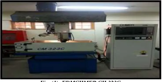
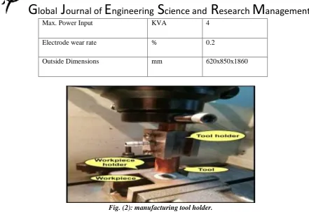
In this research, we used the programmed Electric Discharge Machine (CNC EDM) type CHMER CH (323C+50N), as shown in Figure (1) with operational specifications as shown in Table (1). The machine contains of several mechanical and electrical parts to control the movement of axes, especially the work axis z, which is perpendicular to the axis of the workpiece and controlled by the program. For holding the electrode, a special holder has been manufactured, which contains a central hole intended to make the condensation fluid pass through it and shed it on the operating area, as shown in Figure (2).
Fig. (1): EDMCHMER CH 323C.
Table (1): Technical Specifications of CHMER CH 323C.
Machine body Unit CM 323C
Table Size (WxD) mm 500x350
Work Tank Size(WxDxH) mm 820x500x300
Outside Dimensions mm 1200x1350x2250
Max. Electrode Weight kg 60
Max. Workpiece Weight kg 500
Power Supply Unit 50N
[Abbas* 5(8): August, 2018] ISSN 2349-4506
Impact Factor: 3.799
G
lobal
J
ournal of
E
ngineering
S
cience and
R
esearch
M
anagement
Max. Power Input KVA 4Electrode wear rate % 0.2
Outside Dimensions mm 620x850x1860
Fig. (2): manufacturing tool holder.
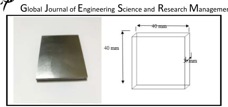
The workpiece material was chosen from high-speed steel (HSS) due to its high strength, high corrosion and shock resistance, with a hardness of HRC 62 (Kg/mm2). The HSS workpiece dimensions is (40 x 40) mm of a
cross-section and 200 mm length. Table (2) shows the chemical composition of the samples. The samples were cut by (40 x 40) mm in a square and 3 mm thick using the wire EDM and as shown in Figure (3).
Table (2): Chemical Composition of HSS Workpiece.
A sample of high speed steel was inspected at the Ministry of Planning/Central Organization for Standardization and Quality Control. The results of this chemical analysis are consistent with the specifications associated with the HSS used in the tests. This is represented by (HS 10-4-3-10) and according to ISO 2002.
Material C% Si% Mn% P% Co% Cr% Mo%
Result 1.34 0.372 0.279 0.0355 9.13 4.43 3.85
Ni% V% AL% Cu% S% Ti% Fe%
Result 0.202 3.04 0.0084 0.209 0.0125 <0.0005 Bala
[Abbas* 5(8): August, 2018] ISSN 2349-4506
Impact Factor: 3.799
G
lobal
J
ournal of
E
ngineering
S
cience and
R
esearch
M
anagement
Fig. (3): the dimensions of workpieces before machining.
The pure copper metal electrode, which has high conductivity specifications is selected to the operation as a positive pole with a diameter of (25, 01) mm and a length of (50) mm.
Table (3) also shows the chemical composition of the copper electrode metal, where the chemical structure has been examined in the Central Organization for Standardization and Quality Control, which conforms to the standard (EN CW004A).
Table (3): Chemical Composition of Copper Tool Electrode.
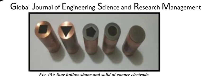
Four hollow electrode shapes are selected in addition to the solid ones, in order to show their effect on the outputs parameters been mentioned. According to mathematical calculation based on equal cross-section for each electrode shape, the area was selected as (157.524 mm2) as shown in Figure (4).
Wire EDM was used for electrode set-up and achieved four hollow geometric shapes (square, triangle, polygon and finally circular) in addition to the basic shape, which is a cylindrical solid and represents the fifth shape as shown in the Figure (5). Which have constant area for all hollow shapes and is estimated at (157,524mm2). In order to manufacture the hollow shape which have been selected, a software called (cimco edit)
used to generate the required G-code program and transmuted to the wire-ED machine which is used to control the axis.
Fig. (4): sketch of five hollow shape of copper electrode.
[Abbas* 5(8): August, 2018] ISSN 2349-4506
Impact Factor: 3.799
G
lobal
J
ournal of
E
ngineering
S
cience and
R
esearch
M
anagement
Fig. (5): four hollow shape and solid of copper electrode.
The experimental design is very important to determine the number of experiments needed. Using Taguchi Method, It involves three parameters and two levels (32); hence, the Taguchi Orthogonal Array Design of
experiments is nine (9). The levels of the two machining parameters were pulse on time and current, as shown in Table (4).
Table (4): The machining parameters.
No
Machining
parameters Symbol Unit
Levels
Level 1 Level 2 Level 3
1 Current I
p A 4 10 16
2 Pulse on time Ton µs 50 100 150
In addition, this experiment design is a design for each of the selected shapes, the remaining parameters were selected and are not subject to change. After several tests were made before the final parameters were set. The unchanged machine parameters shown in Table (5).
Table (5): the unchanged machine parameters. Time-off (TOFF) 25 (µs) Constant
H.V 140 V , 1.2 A =
Gap code 9 =
SVO 75% =
W.T (µs) 0.5 =
J.T (mm) 0.5 =
[Abbas* 5(8): August, 2018] ISSN 2349-4506
Impact Factor: 3.799
G
lobal
J
ournal of
E
ngineering
S
cience and
R
esearch
M
anagement
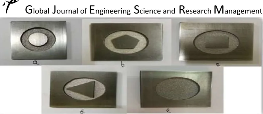
Fig. (6): five hollow shape of HSS workpiece: a- circular shape produced by hollow electrode, b- polygon shape produced by hollow electrode, c- Square shape produced by hollow electrode, d- triangle shape
produced by hollow electrode and e- circular shape produced by hollow tube electrode.
For the purpose of measuring output response, there are several tools used to define and find the purpose of this objective.
The rate of removal of the metal or (MRR) is measured by the weighting of each workpieces before the machining, and then operate the workpiece on the electric sparking machine or (EDM), after that the part is cleaned, dielectric liquid removed, the dirt is quitted and dried, and then the workpiece is weighed again. Sensitive weights device (Denver Instrument) is used which have the accuracy of (± 0.001) gm, and the mathematical formula for MRR (mm3/min) were used to calculate as showing in the relation (1) [22].
MRR = W𝑖𝑤− W𝑓𝑤
𝜌𝑤𝑡
… … (mm
3
min) … … … . . … . . ( 1 )
Where:
W𝑖𝑤 =primary weight of workpiece (gm).
W𝑓𝑤= final weight of workpiece (gm).
ρw= density of workpiece (gm/mm3).
t =period time of the machining process (min.).
The same procedure was done to find the marital removal rate (MRR), but here is done on the electrode wear ratio. The expression for EWR (mm3/min.) is stated fitting to relation (2) [23].
EWR =W𝑖𝑒− W𝑓𝑒
ρet
… … (𝑚𝑚
3
min) … … … . … … … … . … . . ( 2 )
Where:
W𝑖𝑒=primary weight of electrode (gm).
W𝑓𝑒=finalweight of electrode (gm).
ρe=density of electrode (gm/mm3).
t = period time of the machining process (min.).
RESULTS AND DISSECTIONS
[Abbas* 5(8): August, 2018] ISSN 2349-4506
Impact Factor: 3.799
G
lobal
J
ournal of
E
ngineering
S
cience and
R
esearch
M
anagement
Influence of current on MRR for different hollow shapes
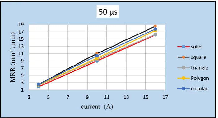
Figure (7) shows the relationship between the current and the material removal rate at the pulse-on time of (50µs) for the models of four hollow electrodes shapes including solid electrode. The results have shown that there is a clear superiority of the square hollow electrode on its peers in the shapes mentioned above. For example, when the current value is (16A), the rate of removal of the metal was (18.5718 mm3/min), while the results show that
the triangle shape gives the lowest value in that moment. This is due to the fact that the hollow square shape plays a crucial role in giving a high rate of removal of the metal compared to other shapes, as the rate of removal of the metal increases with increasing current.
A high current generates a high-intensity spark and as has been inferred in the results, thus increasing the thermal flux of the internal cavity. As a result, the heat of the spark area increases sharply, which leads to a frequent melting of the contact area of the workpiece, this difference is estimated by a percentage of (12.971 %).
Fig. (7): The influence of current on material removal rate (MRR) within 50 µs for five shapes.
It is also noticed that at the current of (10A), the hollow square shape is also superior to the rest of the shapes, where the rate of removal of the metal is (11.01023 mm3/min), while it was found that the lowest rate of removal
of the metal is in the solid electrode. This is the same as mentioned above when the current is (16A) and the difference is expressed by a percentage of (18.49%). As for the lowest current used, it was observed that there is no effect on the rate of removal of all the electrodes used. The reason for this is mostly due to the thermal flux of the internal cavity which is equal in all shapes because the process of cleaning the slag using the insulating liquid oil of the transformers is equal and fast, the amount of heat generated is low and its effect is equal in all shapes.
Figure (8) shows the relation between current and MRR at a TON of (100µs), where increasing the current increases
the MRR. Also as observed by the results at the current of (4A) there is no effect on the material removal rate where the values were close and due to the lack of thermal activity and electric spark and as mentioned earlier at pulse-on time of (50 µs). At the current of (10A), it is noticed that the hollow square shape has the precedence over the rest of the shapes at a value of (14.2459 mm3/min) and the lowest value was observed in the solid electrode
where the difference is represented by the percentage of (25.515%). The reason for this is the same as in the previous paragraph of Figure (7). For the current of (16A), also the hollow square shape has the advantage over the rest of the shapes and follows the same as in the current of 10A. The change is that the lowest value for the Material Removal Rate is for the polygon shape and the highest value for the hollow square shape is (23.20916 mm3/min). Also, the percentage difference is (12.441%).
1 3 5 7 9 11 13 15 17 19
3 5 7 9 11 13 15 17
MR R ( m m 3\ m in )
current (A)
[Abbas* 5(8): August, 2018] ISSN 2349-4506
Impact Factor: 3.799
G
lobal
J
ournal of
E
ngineering
S
cience and
R
esearch
M
anagement
Fig. (8): The influence of current on Material Removal Rate (MRR) at 100 µs for five shapes.
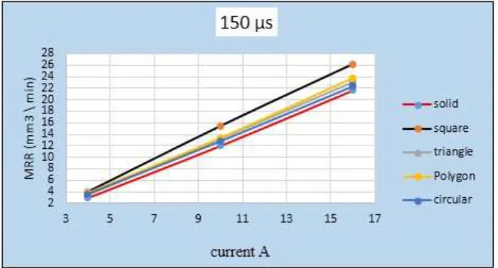
As for figure (9), what mentioned above is applied here, but the difference is in pulse-on time, which is (150µs). Hence it is obvious that the increase of current will increase the MRR significantly.
Fig. (9): The influence of current on material removal rate (MRR) within 150 µs for five shapes.
Influence of current on EWR for different hollow shapes
[Abbas* 5(8): August, 2018] ISSN 2349-4506
Impact Factor: 3.799
G
lobal
J
ournal of
E
ngineering
S
cience and
R
esearch
M
anagement
Fig. (10): The influence of current on electrode wear ratio (EWR) at 50 µs for five shapes
By increasing the current up to (10A), it has been observed that the difference has increased significantly between hollow shapes and the solid electrode at a percentage of 92.976 % relative to the hollow square shape, compared with other shapes, the corresponding percentages are as follows: (86.235%, 85.724%, and 89.60%) for triangle, polygon, and circular shapes, respectively. As for the current of (16A), the difference is still significantly large, but with different percentages as following (87.20%, 76.35%, 82.27% and 55.130%) for the square, triangle, polygon and finally circular shapes, respectively. Meaning that the spark zone is large in the contact area and that leads to an increase in the rate of thermal stresses, causing the generation of layers of cracks due to the fact that the dielectric liquid is not shed efficiently between the electrode and the workpiece during operation, where the flow of dielectric fluid is from outside passing through the electrode face. The spread and width of cracks are highly affected by current. In low-value currents, the width and length of the cracks are relatively low compared to the high currents.
At a pulse-on time of (100 µs), it is also observed in Figure (11) that the hollow electrodes are preferred on the solid electrode. For example, at the current of (4A) it is noticed that there is a huge difference between the electrodes with a rate up to 91% and the hollow square shape is of the least electrode wear ratio by 0.04295.
Fig. (11): The influence of current on electrode wear ratio (EWR) at 100 µs for five shapes
0 0.2 0.4 0.6 0.8 1 1.2 1.4
3 8 13
E WR ( % ) current (A)
50 µs
solid square triangle Polygon circular 0 0.2 0.4 0.6 0.8 1 1.2 1.43 5 7 9 11 13 15 17
[Abbas* 5(8): August, 2018] ISSN 2349-4506
Impact Factor: 3.799
G
lobal
J
ournal of
E
ngineering
S
cience and
R
esearch
M
anagement
As a rising in current value of (10A), it has been noticed that there is a great difference between the lowest readings of the electrode wear ratio for the hollow square shape up to (92.5%) with the solid electrode. For the (16A) current, it is also noticed that the square shape has the lowest wear ratio of (79.61%) compared to the solid shape, followed by the triangle (69.72%), the polygon (54.2%) and finally the circular shape which is less than the solid in about (41.76%). It is observed that (Figure 12) behaves in the same manner as in the previous figures (10) and (11) where the relationship is exponential, the only difference here is the use of pulse-on time (150µs).Fig. (12): The influence of current on electrode wear ratio (EWR) at 150 µs for five shapes
In the current of (4A), it was observed that there is no difference in the electrode wear ratio of all hollow shapes, only there is a difference between the solid electrode and the hollow shapes where the rates are as follows: (89.79%, 87,40%, 84.78% and 82.1%) for the square, triangle, polygon, and circular shapes, respectively.
When the current was increased to 10A, the differences between the hollow shapes and the solid electrode were recorded as follows: (92.16%, 84.87%, 84.31% and 73.93%) for the square, triangle, polygon and finally circular shapes, respectively. At the current of 16A, it was found that there was a difference between the hollow geometric shapes on the one hand and the electrode on the other. Through the results, the differences are as follows :( 60.33%, 53.62%, 25.64 and 18.65%) for the square, triangle, polygon and finally the circular shapes, respectively.
Through the previous observations mentioned above, the hollow square shape was found to be the best and most suitable in terms of the electrode wear, as it has the lowest wear percentage.
CONCLUSIONS
This search show that the effectiveness of several EDM parameters (current and pulse on time) on material removal rate and electrode wear ratio for application of different copper electrodes:
1. It was found that the highest value of material removal rate for a hollow square shape was 26.20910 mm3/min
compared with the solid electrode, which is 21.65502 mm3/ min.
2. The hollow square shape has a superior lower percentage of EWR compared with the solid electrode, which reaches 92.976% at Ton(50) and (10 A).
3. Through the extracted results, the hollow square shape has the best results over the rest of the hollow shapes and also when compared with the solid electrode.
[Abbas* 5(8): August, 2018] ISSN 2349-4506
Impact Factor: 3.799
G
lobal
J
ournal of
E
ngineering
S
cience and
R
esearch
M
anagement
REFERENCES
1. T. Modi, S. Sanawada and J. Patel, A review paper on optimization of process parameter of EDM for air hardening tool steel, International Journal of Engineering Research and Applications, Vol. 5, Issue 1, pp. 32-37, 2015.
2. K.H. Ho and S.T. Newman, "State of the art electrical discharge machining (EDM)", International Journal of Machine Tools and Manufacture, Vol. 43, pp. 1287-1300, 2003.
3. Shukry Hammed Aghdeab, "Experimental and numerical investigation of cutting non-conducting materials by EDM/ESM technique", thesis Submitted to department of production engineering and metallurgy, university of Technology, 2008.
4. Hassan A. G. El-Hofy "Advanced Machining Processes (Nontraditional and Hybrid Machining Processes) “, McGraw-Hill2005. PP.120.
5. John. E. F., "Electrical discharge machining", Rockwell International, ASM Metals Handbook, Vol. 16 Machining, pp. 557-564, 1997.
6. Hoang Vinh Sinh "A method to reduce the relative wear in EDM die sinking processes by reversed pulse", Department of Industrial Automation, Hanoi University of Technology - VietNam, 2004 7. Elman C. Jameson, "Book: Electrical Discharge Machining", Society of Manufacturing Engineers,
pp.1-3, 2001.
8. N. Pellicer, J.Ciurana and J. Delgado, Tool electrode geometry and process parameters influence on different feature geometry and surface quality in electrical discharge machining of AISI H13 steel, Springer Science+ Media,Vol.22, PP.575-584, 2009
9. A. Khan, M. Ali and M. Haque, A study of electrode shape configuration on the performance of die sinking EDM, International Journal of Mechanical and Materials Engineering (IJMME), Vol. 4, No. 1, pp. 19 -23, 2009.
10. Reddy, P. Rao, J. Kumar and K. Reddy, Parametric study of electric discharge machining of AISI 304 stainless steel, International Journal of Engineering Science and Technology, Vol. 2, No.8, pp. 3535-3550,2010.
11. M. Rahman, M. Khan, K. Kadirgama, M. Noor and R. Bakar, Experimental investigation into electrical discharge machining of stainless steel 304, Journal of Applied Sciences, Vol. 11, No. 1, pp. 549-554, 2011.
12. T. Rajmohan, R. Prabhu, G. Rao and K. Palanikumar, Optimization of machining parameters in electrical discharge machining (EDM) of 304 stainless steel, Procedia Engineering, Vol. 38, No. 1, pp. 1030-1036, 2012.
13. S. Rajesha, A.K. Sharma, and Pradeep Kumar, On Electro Discharge Machining of Inconel 718 with Hollow Tool, Journal of Material Engineering and Performance, Vol. 12(6) , PP.882-891, 2012. 14. S. Jaspreer, S. Mukhtiar and S. Harpreet, Optimization of machining parameters in electrical discharge
machining for 202 stainless steel, IJMER, Vol. 3, Issue.4, pp.2166-2169, 2013.
15. S. Singh, N. Kumar and A. Kuma, Experimental investigations of EDM to optimize surface roughness of titanium alloy (Ti-6AL-4V) through Taguchi’s technique of design of experiments, International Journal of Current Engineering and Technology, Vol.4, No.1, pp. 84-87, 2014.
16. K. Kiran, G. Reddy, A. Prasad and R. Rajendra, Study of surface integrity characteristics on Al and die steel components using copper tool in sink EDM process, International Journal of Current Engineering and Technology, Special Issue-2, pp. 236-241, 2014.
17. M. Tawfiq, S. Najem, Optimization of electrode wear rate on electrical discharge machining AISI 304 SS with multi hole electrode, International Journal of Mechanical Engineering and Technology, Vol. 5, Issue 7, pp. 113-124, 2014.
18. Sanjay Kumar Majhi, T.K.Mishra, M.K.Pradhan and Hargovind Soni, " Effect of Machining Parameters of AISI D2 Tool Steel on Electro Discharge Machining", International Journal of Current Engineering and Technology, Vol-4, 2014.
[Abbas* 5(8): August, 2018] ISSN 2349-4506
Impact Factor: 3.799
G
lobal
J
ournal of
E
ngineering
S
cience and
R
esearch
M
anagement
20. Eshraq. A. Dawod, Performance Comparison between Solid and Hollow Electrodes in EDM Drilling, Athesis Submitted to the Department of Production Engineering and Metallurgy/University of Technology,2016
21. S. Yadav and Manoj. K. Gaur, Parametric Optimization of MRR & TWR on Electro Discharge Machining by using Taguchi,s Method and Anova, IJEECS, Vol. 5, Issue.5, 2016.
22. Mikeel P. Grover, "Fundamental of Modern Manufacturing", John Wiley & Sons, Inc, chapter. 27, pp. 691, 1999.