Volume 2, Issue 5, May 2013
Page 222
A
BSTRACTThe FEA analysis of Tie rod is carried out to check its natural frequency, maximum stress analysis and deformation. The most percentage weight of vehicle is taken by suspension system; however tie rod may get fail due to fluctuating forces during steering and bumping of vehicle .The forces from the steering is also considered during the static condition of car. Vibration and fatigue of
Tie rod has been continuously a concern which may lead to structural failure if the resulting vibration and stresses are severe and excessive. It is a significant study which requires in-depth investigation to understand the structural characteristics and it dynamic behavior. This paper presents and focuses on some Finite Element (FE) analysis of a typical tie rod of a car will be carried out and natural frequency will be determined.
Keywords: FEA; Modal FEA; Natural frequency; Forces coming on tie rod;
1.
I
NTRODUCTIONTie rod of Steering system connects center link to the steering knuckle in conventional suspension system and rack to the steering knuckle in McPherson suspension system. Tie rod generally gets force from rack and transfer it to the steering knuckle to turn the wheels. Tie rod is a circular rod with threaded part, Outer end and inner end. Tie rod is mostly made up of alloy steel.
Fig.No.1 McPherson Suspension system
Fig.No.2 Tie Rod End
FEA of Tie Rod of Steering System of Car
Manik A. Patil1, Prof. D.S.Chavan2, Prof.M.V.Kavade3 Umesh S. Ghorpade4
1,2,3&4
Mechanical Engineering Dept. Rajarambapu Institute of Technology, Sakharale.
Volume 2, Issue 5, May 2013
Page 223
Fig.No.3 Tie Rod
Failure of tie rod may cause instability of vehicle and can cause an accident. So it’s important to check the strength of tie rod. The load coming on tie rod is mostly compressive. The efforts required where car is moving are comparatively less with stationary car. The working strength of the tie rod is that of the product of the allowable working stress and the minimum cross-sectional area.
If the threads are cut into a cylindrical rod, that minimum area can be found at the root of the thread. Rods are often made thicker at the ends and this then means that the tie rod does not become weaker when the threads are cut into it. Tie rods are connected at the ends in various ways. But it is desirable that the strength of the connection should be at least an equal strength to that of the rod. The ends can be threaded and then passed through drilled holes or shackles (this is a U-shaped piece of metal that is secured with a pin or bolt across the opening), and then retained by nuts that are screwed on the ends. If the ends are threaded right hand and left hand, the length between the points of loading may be altered. A turnbuckle is a device that is used for adjusting the tension in tie rods. Another way of making any end connections is to forge an eye or hook on the rod. It is advisable that your vehicle's steering and suspension systems are checked regularly, at least once a year along with a complete wheel alignment. A worn tie rod can cause wandering, erratic steering and also major tire wear. If a tie rod is necessary then a wheel alignment will also be required because tie rod replacement will disturb the alignment setting. As the ratio of its length to the radius of gyration of its cross section is normally quite large, it would likely buckle under the action of compressive forces. The tie rod transmits force from the steering center link or the rack gear to the steering knuckle. This will cause the wheel to turn. The outer tie rod end connects with an adjusting sleeve, which allows the length of the tie rod to be adjustable. This adjustment is used to set a vehicle's alignment angle. The steering and suspension system of car should be checked periodically because worn tie rod can create wandering of steering and excessive tire wear. Failure of tie rod may occur due to improper material selection, poor design, fatigue load and wear of tie rod. Also the indications given by the tie rod before failure is very less so it can be risky.
2.
L
ITERATURER
EVIEWSuraj Joshi et al [1] concluded from their work that in order to minimize the probability of shear and bending failure occurring in the engaged thread teeth on a steel tie rod in service, the number of engaged thread turns should be kept as low as possible. When the number of engaged turns is lower than eight, failure occurs at the engaged threaded connection in the form of shearing and then pulling out of the thread teeth in both the triangle and trapezoidal type thread connections. When the number of engaged turns is exactly eight, failure occurs at the middle part of unengaged thread (near the 16th turn) in the form of necking and then breaking of the cross-section of the tooth root on unengaged thread.
A.H. Falah et al [2] conducted study on a failed tie rod end of a SUV. Spectrum analysis and hardness measurement revealed that the failed part was AISI 8620 steel. The composition and hardness did not conform to the specified
standard. Fractographic features indicated that fatigue was the main cause of failure of the tie rod end. On the fracture surface of the threaded part of the rod, the crack initiation region and beach marks could be clearly identified. Failure
analysis results indicate that the primary cause of failure of the tie rod was likely material deficiency. Formation of the
Volume 2, Issue 5, May 2013
Page 224
George Campbell, Wen Ting [3] tested on a large scale finite element model of a tie rod in NASTRAN Version 68.The static buckling load of a tie rod is analyzed. The results of the finite element model are compared with experimental results. The analysis is performed in three steps. First, linear buckling is analyzed with SOL 105. Second, a nonlinear static analysis with arc length method is performed in SOL 106 to determine the instability behavior of the structure. In the last step, a nonlinear buckling analysis is done with restart into SOL 106 to determine the nonlinear buckling load. The tie rod has a strongly nonlinear behavior which is due to material yield and geometric nonlinear effects.
Sergio Lagomarsino, Chiara Calderini [4] studied the tensile axial force of metallic tie-rods in masonry arches and vaults. The identification procedure uses the first three modal frequencies of the tie-rod, measured by means of a dynamic test. The reference structural system consists of a beam with uniform section, subjected to an axial tensile force and spring-hinged at both ends. Besides the axial tensile force, the unknown variables are the bending stiffness of the section and the stiffness of the rotational springs. Since the characteristic equation of this structural system does not allow analytical solutions, the paper proposes an approximate numerical solution, based on a minimization procedure of a suitable error function. The robustness of the method is tested by identifying a number of ideal tie-rods, modeled by means of a FEM code.
Michael Adam Kaiser [5] has made specific advancements in the technique to better align the stress and strain pulses using changes in slope instead of absolute time. He also worked on optimization technique for determining specimen diameter based on the impedance mismatch occurring at the interface of two materials. He worked on the technique for determining dispersive properties of longitudinal bars using existing Hopkinson bar apparatus.
3.
P
ROPOSEDM
ETHODOLOGYAt first the theoretical study of Tie-rod is done. The overall purpose of Tie-rod is to transmit the motion from steering arm to steering knuckle and sustain the forces and vibrations caused by bumps from tires due to uneven road surfaces. The key areas for modification are identified. The main task in this study is to find the deformation and stresses induced in the Tie-rod and optimizing it for various material combinations. The 3-Dimensional model is prepared for Tie-rod. Different types of materials are assigned and analysis is carried out using finite element analysis software named Ansys Inc. The results are compared with practical results.
4.
A
NALYSIS OFT
IE-
RODFinite element analysis (FEA) is one of the most popular engineering analysis methods for Non linear problems. FEA requires a finite element mesh as a geometric input. This mesh can be generated directly from a solid model for the detailed part model designed in a three-dimensional (3D) CAD system. Since the detailed solid model (see Fig.4) is too complex to analyse efficiently, some simplification with an appropriate idealization process including changing material and reducing mesh size in the FE model is needed to reduce the excessive computation time. The Tie rod are made of up Alloy Steel. For thin bodies, a different type of meshing approach is required. For Tie rod part, we extracted and meshed the mid-surface using Hex Dominant Quadrilateral and Triangular elements. Fig. 6 shows the FEM model of the existing design. The existing design has circular rod, threaded part, outer and inner end. Threaded part is fixed and remaining part has compressive force of 4017.195 & 890.65 N. This force is produced from bumping force and steering force respectively. There is also self weight (g). The material used for FE Analysis is Non Linear. The FEM Model having 6 freedoms: translations in the nodal x, y, and z directions and rotations about the nodal x, y, and z axes.
FEA Procedure is as follows;
1)First up all 3D model of Tie rod is prepared by using CATIA VR 5 software.
Volume 2, Issue 5, May 2013
Page 225
2)This model is then imported to ANSYS software for further analysis.
Fig.No.5 3D model of Tie rod of steering system in Ansys Software. 3)Meshing of Tie Rod
Fig.No.6 Mesh model of Tie rod of steering system in Ansys Software.
4)Different boundary conditions like Fixed support and forces are applied on the tie rod.
Fig.No.7 Boundary conditions applied on the model of Tie rod of steering system in Ansys Software.
5)After meshing & boundary condition applied, ANSYS solves this problem and determines different values of Deformation and stresses.
Volume 2, Issue 5, May 2013
Page 226
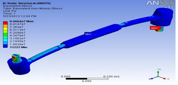
Fig.No.9 Equivalent (von misses) stresses of Tie rod of steering system in Ansys Software.
6) After Completion of static analysis, we do the modal analysis and get value of natural frequency.
Fig.No.10 Natural Frequency of Tie rod of steering system in Ansys Software.
5.
RESULT
Result for static Analysis;
Table 1: Result Table for Static Analysis
Sr.no Deformation (M)
Equivalent (Von-misses) Stresses
(pa) 1 0.00013302 9.4664 * 10^7 Result for Modal Analysis;
Table 2: Result Table for Modal Analysis
Sr.no Mode Natural Frequency (Hz)
1 1 291.30
2 2 303.12
3 3 666.24
4 4 847.55
5 5 885.31
Volume 2, Issue 5, May 2013
Page 227
Fig.No.11 Graph of Modes vs Natural Frequency.
6.
CONCLUSION
The conducted research has begun with creation of 3D-CAD solid approximate model in the form of a multi-body system, after that solid mesh was generated where all meshed elements assumed to be perfectly rigid, and in final stage of testing finite element analysis was performed using Ansys software package. From the presented results we can conclude that the distribution of deformation and stress do not exceed the yield strength value and that there are neither damages nor failure of Tie rod. The correctness and accuracy of computed results is still dependent on the selection related to various modeling parameters. Some of the most important aspect such as boundary conditions or correct mesh and type of elements are performing a decisive role in achieving of correct results. Tie rod analysis by using ANSYS software shows that the deformation is 0.13302 mm and the equivalent stress is 94.66 Mpa which is less than tensile and compressive yield strength i.e 250 mpa. The Tie rod undergoes continuous vibrations when vehicle is running. Hence Natural Frequency is calculated in Ansys software and its value is 201.30Hz. From the above results the tie rod taken for analysis is safe.
References
[1.] A.H. Falah *, M.A. Alfares, A.H. Elkholy, “Failure investigation of a tie rod end of an automobile steering system”, Mechanical Engineering Department, Kuwait University, P.O. Box 5969, Safat 13060, Kuwait 19 November 2006.
[2.] Wei Duan a, Suraj Joshi, “Failure analysis of threaded connections in large-scale steel tie rods”, Department of Mechanical and Industrial Engineering, Concordia University, Sir George Williams Campus, 1515 St. Catherine Street West.
[3.] Sergio Lagomarsino ,ChiaraCalderini, “The dynamical identification of the tensile force in ancient tie-rods”, Department of Structural and Geotechnical Engineering, University of Genoa, Via Montallegro 1, 16145 Genova, Italy,17 January 2005.
[4.] George Campbell and Wen Ting, “Buckling and geometric nonlinear analysis of a tie rod in NASTRAN VERSION68”, Light Truck Divison, Ford Motor Company.
[5.] Michael Adam Kaiser, “Advancements in the Split Hopkinson Bar”, Test Faculty of the Virginia Polytechnic Institute, Blacksburg, Virginia May 1, 1998.