Sharif University of Technology
Scientia IranicaTransactions A: Civil Engineering www.scientiairanica.com
On the vibration of a thin rectangular plate carrying a
moving oscillator
M. Ebrahimzadeh Hassanabadi, J. Vaseghi Amiri
and M.R. Davoodi
Department of Civil Engineering, Babol University of Technology, Babol, P.O. Box 71167-47148, Iran. Received 16 January 2013; received in revised form 29 June 2013; accepted 20 August 2013
KEYWORDS Rectangular plate; Moving oscillator; Moving mass; Contact force; Benchmark solution.
Abstract.A great number of studies on the vibration of plates subjected to moving loads are available, which are gained by moving force and moving mass modeling frameworks. As a result, evaluating the reliability of the approximate simulation of a moving oscillator problem through moving force/mass would be of interest to engineering applications. Therefore, in this article, transverse vibration of a thin rectangular plate under a traveling mass-spring-damper system is revealed using the eigenfunction expansion method. Both moving force and moving mass modeling approaches are compared with the moving oscillator and various plate xity cases, and load trajectories are involved to present benchmark solutions. The spring stiness range, in which the plate response agrees closely with the corresponding moving force/mass analysis, is recommended. The results elucidate that the moving mass can be considerably unrealistic in predicting the contact force of an undamped oscillator. Moreover, errors in the orbiting force/mass simplication of the orbiting oscillator in predicting the resonant conditions of the plate vibration are not negligible.
c
2014 Sharif University of Technology. All rights reserved.
1. Introduction
The dynamic behavior of structures due to moving loads have been evaluated in several branches of engineering and technology, and the transportation industry is one of the most well-known instances. The magnitude of traveling train and vehicle dynamic loads are coupled with railway, highway and bridge deformation, because of the inertial interaction of the load and the substructure. The inuences of aircraft on airport pavements or on the decks of carrier ships are other examples of moving loads. Moving load consideration is also of importance for a mechanical engineer scrutinizing high speed precision machinery,
*. Corresponding author. Tel.: +98 111 3232071-4; Fax: +98 111 3234201
E-mail addresses: ebrahimzadeh [email protected] (M. Ebrahimzadeh Hassanabadi); [email protected] (J. Vaseghi Amiri); [email protected] (M.R. Davoodi)
computer disk memory and wood saws. Based on the situation, in practice, several types of continuum model excited by the traveling loads can be simulated. These include cables [1,2], beams [3-6], plates and half-space [7], where voluminous literature is currently available devoted to the dynamics of beams acted upon by moving loads (see [8,9]).
Moving force simulation is very customary in approximating the dynamics of structures inuenced by traveling inertial loads with exible suspension systems. A moving force refers to a traveling constant force aecting a continuum, disregarding the inertia of the agent applying the load. In moving mass modeling, the inertia interaction of the load and supporting structure comes into play. Using the moving oscillator formulation yields more realistic results by accounting for the eects of the suspension system. This paper focuses on the 2-D distributed systems undergoing traveling loads, and related published work includes the following.
Cifuentes and Lalapet [10] determined the dy-namic response of a rectangular thin plate undergo-ing an orbitundergo-ing load usundergo-ing the FEM (nite element method), employing an adaptive mesh. Esen [11] developed a new nite element for vibration of rectan-gular plates traversed by a moving mass. Shadnam et al. [12] coped with the vibration of a simply supported rectangular plate due to a moving mass, utilizing the eigenfunction expansion method. The eect of moving mass convective acceleration terms, as well as the weight and velocity of the moving lumped body, has been inspected by Nikkhoo and Rofooei [13] in a comprehensive parametric study. A classical closed looped control algorithm has been proposed by Rofooei and Nikkhoo [14] to suppress the vibration of a simply supported rectangular plate under a moving mass, adopting a number of bounded active piezoelectric patches. They investigated the rectilinear and circular trajectories of the moving load in detail. Wu [15] handled the dynamics of a rectangular plate under a series of orbiting forces using FEM to investigate the eect of rotating speed, radius of the circular path and the number of loads. Wu [16] also developed a technique based on scale beam and scaling law, dealing with the vibration of a rectangular plate subjected to moving line loads (via a moving force approach). In another work, he analyzed the vibration of an inclined at plate under a moving mass by FEM [17]. Sound radiation from the vibration of orthotropic plates under moving loads has been explored by Au and Wang [18], and the eect of light and heavy moving loads have been discussed. A technique based on FEM with adaptive mesh, as well as the perturbation method, is proposed by de Faria and Oguamanam [19], tackling the dynamics of Mindlin plates under traversing loads. Gbadeyan and Oni [20] devoted a study to the dynamic behavior of beams and plates by modied generalized nite integral transforms and the modied Struble method. Takabatake [21] evaluated the vibration of a rectangular plate with stepped thickness acted upon by a moving load. Dynamic response of an initially stressed rectangular plate under a moving mass has been dealt with by Eftekhari and Jafari [22] via the Ritz, Dierential Quadrature and Integral Quadra-ture methods. Vaseghi Amiri et al. [23] studied the transverse vibration of a rectangular shear deformable plate under moving force and moving mass. They compared the FSDT (rst order shear deformation plate theory) with the CPT (classical plate theory) widely. By employing the series expansion of mode functions and applying Banach's xed point theorem, Shadnam et al. [24] represented nonlinear thin plate vibration caused by a moving mass. A semi-analytical solution, as well as an adaptive nite element method, was introduced by Ghafoori et al. [25] to compute the dynamic response of a simply supported rectangular
plate to a moving sprung mass. Mohebpour et al. [26] presented a numerical study of the vibration of a shear deformable laminated composite plate loaded by a moving oscillator.
Moving force/mass results are usually accepted to be equivalent to a moving oscillator having a soft/rigid spring. However, so far, no clear measure seems to be given to categorize the softness/rigidness of the suspension system for a specic problem. Moreover, the resonance of a plate vibration due to an orbiting oscillator has also not been accounted for yet. Thus, in this article, it is proposed to give an initial estimate for a soft or sti spring. The plate resonant state, due to an orbiting oscillator, is also discussed. The moving oscillator trajectory and the xity condition of the plate are not conned to a specic case in the given numerical examples. Moreover, the contact force between the moving oscillator and the plate is compared with that revealed by the moving mass. The presented solution in this paper is considerably time-saving in comparison with the modal analysis of the moving mass. It also provided more realistic results, which makes the introduced technique more qualied to perform parametric studies. The methodology can also be used in future studies as a fast and robust model for detecting possible damage to the structure via Bayesian lters, e.g. the extended Kalman lter, the sigma-point Kalman lter, the particle lter and the extended Kalman-particle lter [27-29].
2. Problem denition and formulations
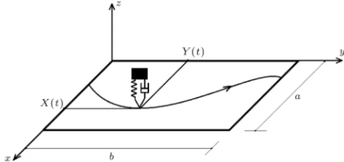
A thin rectangular plate acted upon by a moving mass-spring-damper system traveling along an ar-bitrary trajectory is considered (Figure 1). The trajectory of the moving oscillator is given by the parametric coordinates; (X(t); Y (t)):M; c and k, are the mass, damping and stiness of the oscillator, respectively. v(t) is the distance between the mass and the plate mid-plane and W (X(t); Y (t); t) rep-resents the plate deformation beneath the oscillator (Figure 2).
The constitutive equation of the plate forced
Figure 1. Moving oscillator traversing the plate with (X(t); Y (t)) trajectory.
Figure 2. The position of the mass with respect to the plate mid-plane.
vibration can be written as: 8 > > > < > > > :
Dr4W (x; y; t) + h@2W (x; y; t)
@t2
= P (x X(t))(y Y (t)); D = Eh2
12(1 v3); (1)
in which, E; D; ; h; t and are Young's modulus, plate exural rigidity, mass per unit of volume, thickness of plate, time, and Dirac delta function, correspondingly. The moving oscillator exerts the transverse dynamic force, P , on the plate surface. Regarding the function of the damper and the spring, as well as the inertia of the mass, P should satisfy the dynamic equilibrium. Thus, one can write the equilibrium constraints for the moving mass-spring-damper system as:
( M d2
dt2(v(t) + W (X; Y; t)) + P + Mg = 0;
P = cd
dtv(t) + k(v(t) v0);
(2) where v0 and g are the initial length of the spring and
gravitational acceleration, respectively. The equation of plate free vibration is: Dr4w
i(x; y) = h!2iwi(x; y); (3)
where wi and !i are mode shape and frequency of
plate free vibration, respectively. Since the dierential operator of Eq. (3) is self-adjoint, the eigenfunction expansion of W (x; y; t) can be employed:
W (x; y; t) =
1
X
i=1
ai(t)wi(x; y): (4)
Finding the unknown time dependent coecients, ai(t), leads to the determination of the plate dynamic
response. For normalized mode shapes, one can write: Z
Aplate
Z
hwi(x; y)wj(x; y)dA = ij=
(
0; i 6= j 1; i = j:(5) Let us dene the inner product of:
hwi(x; y); wj(x; y)i =
Z
Aplate
Z
wi(x; y)wj(x; y)dA:
(6) Introducing Eq. (4) into Eqs. (1) and (2), yields:
1
X
i=1
ai(t)Dr4wi(x; y) + hwi(x; y)d 2
dt2ai(t)
= P (x X(t))(y Y (t)); (7-1) M
d2
dt2v(t) + 1
X
i=1
d2
dt2(ai(t)wi(X; Y ))
+ P + Mg = 0: (7-2) By applying an inner product of wj(x; y) on both
sides of Eq. (7-1) and performing some simplications regarding Eq. (3), one can eliminate the space in Eq. (7-1), arriving at:
!2
jaj(t) + d 2
dt2aj(t)
= P wj(X; Y ): (8)
The second order derivative of ai(t)wi(W; Y ), with
respect to time, in Eq. (7-2), can be expanded as: d2
dt2(ai(t)wi(X; Y )) = wi(X; Y )
d2
dt2ai(t)
+ 2
@wi(x; y)
@x
dX dt +
@wi(x; y)
@y dY dt x=X y=Y d dtai(t) +
@2wi(x; y)
@x2 dX dt 2 +
@2wi(x; y)
@y2 dY dt 2 + 2
@2w i(x; y)
@x@y dX dt dY dt +
@wi(x; y)
@x
d2X
dt2
+
@wi(x; y)
@y
d2Y
@t2
x=X y=Y
ai(t):
(9) The solution can be approximated by selecting a nite number of involved mode shapes of free vibration, n, which can be taken large enough, based on the demand for precision.
The matrix version of Eqs. (7-2) and (8) is: M(t)dtd22a(t) + C(t)dtda(t) + K(t)a(t) = F(t); (10)
in which: a(t) = a1 a2
(n+1)1; (11)
M(t) =
M11 M12
M21 M22
(n+1)(n+1); (12)
C(t) =
C11 C12
C21 C22
(n+1)(n+1)
; (13)
K(t) =
K11 K12
K21 K22
(n+1)(n+1); (14)
F(t) =
F1
F2
(n+1)1; (15)
where the sub-matrixes in Eqs. (11)-(15) are: 8
> < > :
a1= [ai(t)]n1
a2= [v(t)]11
v(t) = v(t) v0
(16) 8 > > > < > > > :
M11= [ij]nn
M12= [0]n1
M21= [Mwj(X; Y )]1n
M22= [M]11
(17) 8 > > > > > > > > > > < > > > > > > > > > > :
C11= [0]nn
C12= [ cwi(X; Y )]n1
C21=
2M
@wj(x; y)
@x dX dt +
@wj(x; y)
@y dY dt x=X y=Y 1n
C22= [c]11
(18) 8 > > > > > > > > > > > > > > > > > > > > > > > > < > > > > > > > > > > > > > > > > > > > > > > > > :
K11= [!2iij]nn
K12= [ kwi(X; Y )]n1
K21=
" M
@2wj(x; y)
@x2 dX dt 2 +
@2w j(x; y)
@x2 dY dt 2 + 2
@2w j(x; y)
@x@y dX dt dX dt +
@wj(x; y)
@x
d2X
dt2
+
@wj(x; y)
@y
d2Y
dt2 x=X y=Y # 1n
K22= [k]11
(19)
(
F1= [0]n1
F2= [ Mg]11 (20)
The second order ODEs in Eq. (10) can be replaced by: d
dtQ(t) = A(t)Q(t) + G(t);
Q(t0) = Q0; (21)
where: A(t)=
O(n+1)(n+1) I(n+1)(n+1)
M 1K M 1C
2(n+1)2(n+1);(22)
Q(t) = a(t) d dta(t) 2(n+1)1 ; (23) G(t) = On1
M 1F
2(n+1)1
: (24)
There are several methods to cope with Eq. (21). In this paper, the solution is achieved by the matrixexpo-nential [30].
3. Numerical examples
Six distinct congurations are analyzed in Sections 3.1 and 3.2 according to Figure 3, which are referred to as C-a, C-b, C-c, C-d, C-e and C-f (The trajectories are given in Table 1 and the related eigenfunctions are given in Appendix A.), having set the values below for the parameters:
v = 0:30; g = 9:81 m/s2; = 2400 kg/m2; a = b = 10 m; h = 0:3 m; E = 20 GPa:
In Section 3.3, the validity of the results is evaluated by nite element method. Additionally, an existing railway bridge is assessed in Section 3.4.
T1 = 2=!1 and u0 = a=T1 are introduced to
present normalized time and velocity, in which !1
de-notes the rst natural frequency of the plate. Moreover, Wc is the deformation of the plate center point and
Wsstands for the plate center point static deformation
when the oscillator is located at the center of the plate. (The static deformation caused by P applied at (x0; y0) can be computed by the fast converging
series, W (x; y) = PPni=1[wi(x; y)wi(x0; y0)=!2i]). The
parameters, Mp; and !, are dened as:
Mp = hab; = c=2m!; ! =
p k=M:
By default, at t = 0 the plate and the oscillator are at rest, i.e @W
@t = 0;dvdt = 0 and the initial deformation
of the plate, W (x; y; 0), corresponds to that statically caused due to the oscillator's weight at its initial position, and the initial sag of the spring is assumed to be Mg
Table 1. Parametric coordinates of trajectories in Figure 3.
Conguration X(t) Y (t)
C-a ut 0.5 b
C-b 0.25 a cos(t) + :5a 0.25 b sin(t) + :5b
C-c ut 0.4 b sin1:5X(t)
a
+ 0:5b
C-d 0:5a ut
C-e a ut bX(t)
a
C-f 0.3a cos 2
b Y (t)
+ 0:5a ut
Figure 3. Plate boundary conditions and moving oscillator trajectories: (a) C-a; (b) C-b; (c) C-c; (d) C-d; (e) C-e; and (f) C-f.
The moving mass and moving force results are provided by the eigenfunction expansion method [13], where the employed methods of the state-space solution for a moving force/mass and moving oscillator are the same.
3.1. Modal contribution and computational time cost
The contribution of the rst 5, 25 and 50 natural mode shapes are depicted in Figure 4. The results support that employing 25 modes yields adequate precision within the scale of the diagrams. The presented method results in less time varying coecients in the
Figure 4. Contour plot of W (x; y; t)=Wc when
X(t) = 0:6a (C-a). M = 0:1Mp; ! = 0:5!1; = 0:2 and
u = 1:0u0.
state-space equations, in comparison with the modal analysis of the moving mass, as formulated in [13,23]. Consequently, the computational eort of the current technique requires less CPU usage and runs noticeably faster (see Figure 5). Thus, the proposed technique can be regarded as a suitable choice for parametric studies. 3.2. Comparing moving oscillator, moving
force and moving mass
In Figure 6, the plate center point deformation versus the eigenfrequency of the oscillator is depicted consider-ing an undamped travelconsider-ing oscillator. As evident in the diagram, the time history of the plate deformation does not exhibit an appreciable sensitivity to the variation of spring stiness for ! values greater than 10!1 and
less than 0:1!1. In Figure 7, the dynamic response of
the plate, regarding ! = 0:05!1; 1:0!1, and 20!1 ! is
compared to the moving mass and moving force related analyses. It can be concluded that for ! 0:05!1 and
20!1 !, moving force and moving mass modeling
frameworks yield a plate response very close to that re-vealed by the moving oscillator, correspondingly. Thus,
Figure 5. Comparison of state-space computational time cost of current method and moving mass modal analysis (C-a).
Figure 6. Time history of plate center point response versus oscillator eigenfrequency (C-a).
M = 1:0Mp; = 0:0 and u = 1:0u0.
Figure 7. Time history of plate center point response versus oscillator eigenfrequency (C-a).
M = 1:0Mp; = 0:0 and u = 1:0u0.
the suspension systems with ! 0:05!1 and 20!1
! can be categorized as soft and sti, respectively, considering M MP.
Assessment of the contact force is necessary in the design and durability evaluation of bridges and highway pavements. In most research into the vibra-tion of plates under the acvibra-tion of moving loads, plate deformation has been taken as a dynamic response representation, and the contact force of the moving body and the supporting media has been ignored.
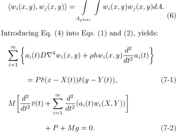
In Figure 8, the contact force of an oscillator with sti suspension is evaluated for the general case of a non-zero initial condition. To this end, the plate is analyzed under the action of 4 moving loads with the same characteristics and velocities. The distance between the loads is and the initial condition of the
Figure 8. Time history of contact force (C-a). M = 0:5Mp; = 0:05; u = 0:4u0; ! = 20!1: (a) 1st load;
plate (Q(0)) at the moment of the next load entrance is regarded the same as when the last load leaves the plate surface (Q(a=u0)). For the undamped oscillator, a
high frequency component is realizable, which oscillates in the vicinity of the moving mass contact force. This high frequency component can signicantly grow when the excitation continues by the next entering load. Therefore, the deciency of the moving mass in modeling an undamped suspension contact force becomes clear. However, the moving mass output for contact force corresponds closely to the traveling oscillator analysis for a damped oscillator with a large enough damping coecient.
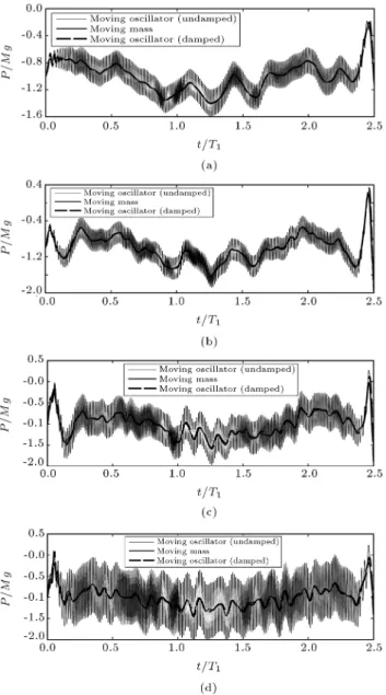
3.2.1. The orbiting load and resonance occurrence Investigating the plate dynamic performance under an orbiting load is of interest when dealing with high speed precision machining processes (see [10,12-14,23,25]). Some researchers have inspected the resonant stats of plate vibration due to the orbiting mass and force, such as those presented in [5,6] and [15]. In Figure 9, the plate resonance is sought for dierent eigenfrequencies of the orbiting oscillator. The results indicate that for 0:2!1 ! 1:0!1, the variation of the
oscil-lator eigenfrequency can considerably alter the plate dynamic performance. Therefore, in this case, the deciency of moving force/mass modeling becomes obvious. Another point worth mentioning is that for an orbiting oscillator, resonance does not take place between the resonant orbiting frequencies computed by the orbiting force and orbiting mass.
3.2.2. Miscellaneous benchmark solutions
Dierent plate boundary conditions (SFSF, SCSF, SSSF and SCSS) and moving oscillator trajectories are
Figure 9. Maximum plate center point deformation in an exciting duration of 50T1 (C-b). M = 0:4Mpand = 0:0.
Figure 10. Plate deformation beneath the moving load (C-c). M = 0:4Mp; = 0:01 and u = 0:8u0.
Figure 11. Plate deformation beneath the moving load (C-d). M = 0:5Mp; = 0:15 and u = 0:5u0.
involved in Figures 10-13. As evident, the sensitivity of the plate response to the variation of spring stiness for 0:2!1 ! 2!1, cannot be ignored. Hence, in general,
the approximate modeling of the moving oscillator when 0:2!1 ! 0:1!1, may yield unrealistic
outputs.
3.3. Verication
A plate with v = 0:25; = 2500 kg/m3, a = 100
m, b = 10 m, E = 31 GPa and h = 0:3 m is considered. The plate is simply supported at edges parallel to the y axis and free along edges parallel to the x axis. A moving load is traveling on the plate
Figure 12. Plate deformation beneath the moving load (C-e). M = 0:6Mp; = 1:2 and u = 0:2u0.
Figure 13. Plate deformation beneath the moving load (C-f). M = 0:5Mp; = 0:6 and u = 0:4u0.
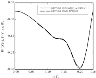
lengthwise along a position vector of (ut; 0:5b). The dynamic response of the plate, due to the traveling oscillator, is compared with that obtained by de Fari and Oguamanam [19] by utilizing the FEM and moving mass approach in Figure 14. The very close agreement of outputs conrms that a moving mass simulation corresponds to a traveling oscillator, having 20!1
!.
3.4. Simulation of an existing bridge
In this section, the vibration of the vinival concrete railway bridge is simulated by making recourse to the presented semi-analytical approach. Vinival is a single
Figure 14. Plate deection under the traveling load. M = 0:01359Mp; = 0 and u = 4:1734u0.
Figure 15. Plate deection under the train wheel. u = u0.
Table 2. Parameters of Vinival Bridge.
a (m) 9.7
b (m) 4.34
D (N.m) 9.4779 108
h (kg/m2) 1483
span and simply supported bridge constructed as part of the Spanish railway network [31]. The mechanical properties of the bridge are given in Table 2. An Italian ETR500Y high speed train is traversing the bridge with the same trajectory described in Section 3.3. The mass, stiness and damping of the train SDF equivalent model are set as M = 27988 kg, k = 618368 kN/m and c = 15250 kNs/m, respectively. As shown in Figure 15, underestimation of plate response by moving force is noticeable, while the moving mass simulation shows excellent agreement with that of the moving oscillator in this specic case.
4. Conclusions
Transverse vibration of a thin rectangular plate excited by a moving oscillator has been tackled using a semi analytical method. The introduced method runs no-ticeably faster with respect to the modal analysis of the moving mass. SSSS, SFSF, SSSF, SCSF and SCSS boundary conditions are involved, as well as a variety of trajectories, to present benchmark solutions. The precision of the moving force and mass simulations are assessed with the moving oscillator exact formulation. For an undamped moving oscillator with !1 0:05!1
and 20!1 !, and , the moving force and moving mass
simulations can predict the plate response very close to the real results, respectively. Furthermore, simplifying an orbiting oscillator by moving force/mass to achieve resonant frequencies can cause considerable errors. References
1. Wang, L. and Rega, G. \Modelling and transient planar dynamics of suspended cables with moving mass", International Journal of Solids and Structures, 47(20), pp. 2733-2744 (2010).
2. So, A. \Nonlinear in-plane vibrations of inclined cables carrying moving oscillators", Journal of Sound and Vibration, 332(7), pp. 1712-1724 (2013).
3. Eftekhar Azam, S., Mod, M. and Afghani Khoraskani, R. \Dynamic response of Timoshenko beam under moving mass", Scientia Iranica, Transactions A: Civil Engineering, 20(1), pp. 50-56 (2013).
4. Ebrahimzadeh Hassanabadi, M., Nikkhoo, A., Vaseghi Amiri, J. and Mehri, B. \A new orthonor-mal polynomial series expansion method in vi-bration analysis of thin beams with non-uniform thickness", Applied Mathematical Modelling (2013) <http://dx.doi.org/10.1016/j.apm. 2013.03.069>. 5. Dehestani, M., Mod, M. and Vafai, A. \Investigation
of critical inuential speed for moving mass problems on beams", Applied Mathematical Modelling, 33(10), pp. 3885-3895 (2009).
6. Nikkhoo, A., Rofooei, F.R. and Shadnam, M.R. \Dy-namic behavior and modal control of beams under moving mass", Journal of Sound and Vibration, 306(3-5), pp. 712-724 (2007).
7. Dehestani, M., Vafai, A. and Mod, M. \Steady-state stresses in a half-space due to moving wheel-type loads with nite contact patch", Scientia Iranica, Transactions A: Civil Engineering, 17(5), pp. 387-395 (2010).
8. Fryba, L. Vibration of Solids and Structures under Moving Loads, Thomas Telford, London (1999). 9. Ouyang, H. \Moving load dynamic problems: A
tutorial (with a brief overview)", Mechanical Systems and Signal Processing, 25(6), pp. 2039-2060 (2011).
10. Cifuentes, A. and Lalapet, S. \A general method to determine the dynamic response of a plate to a moving mass", Computers & Structures, 42(1), pp. 31-36 (1992).
11. Esen, _I. \A new nite element for transverse vibration of rectangular thin plates under a moving mass", Finite Elements in Analysis and Design, 66, pp. 26-35 (2013). 12. Shadnam, M.R., Mod, M. and Akin, J.E. \On the dynamic response of rectangular plate, with moving mass", Thin-Walled Structures, 39(9), pp. 797-806 (2001).
13. Nikkhoo, A. and Rofooei, F.R. \Parametric study of the dynamic response of thin rectangular plates traversed by a moving mass", Acta Mechanica, 223(1), pp. 15-27 (2012).
14. Rofooei, F.R. and Nikkhoo, A. \Application of ac-tive piezoelectric patches in controlling the dynamic response of a thin rectangular plate under a moving mass", International Journal of Solids and Structures, 46(11-12), pp. 2429-2443 (2009).
15. Wu, J.J. \Vibration of a rectangular plate undergoing forces moving along a circular path", Finite Elements in Analysis and Design, 40(1), pp. 41-60 (2003). 16. Wu, J.J. \Dynamic analysis of a rectangular plate
under a moving line load using scale beams and scaling laws", Computers and Structures, 83(19-20), pp. 1646-1658 (2005).
17. Wu, J.J. \Vibration analyses of an inclined at plate subjected to moving loads", Journal of Sound and Vibration, 299(1-2), pp. 373-387 (2007).
18. Au, F.T.K. and Wang, M.F. \Sound radiation from forced vibration of rectangular orthotropic plates un-der moving loads", Journal of Sound and Vibration, 281(3-5), pp. 1057-1075 (2005).
19. de Faria, A.R. and Oguamanam, D.C.D. \Finite ele-ment analysis of the dynamic response of plates under traversing loads using adaptive meshes", Thin-Walled Structures, 42(10), pp. 1481-1493 (2004).
20. Gbadeyan, J.A. and Oni, S.T. \Dynamic behaviour of beams and rectangular plates under moving loads", Journal of Sound and Vibration, 182(5), pp. 677-695 (1995).
21. Takabatake, H. \Dynamic analysis of rectangular plates with stepped thickness subjected to moving loads including additional mass", Journal of Sound and Vibration, 213(5), pp. 829-842 (1998).
22. Eftekhari, S.A. and Jafari, A.A. \Vibration of an initially stressed rectangular plate due to an acceler-ated traveling mass", Scientia Iranica, Transactions A: Civil Engineering, 19(5), pp. 1195-1213 (2012). 23. Vaseghi Amiri, J., Nikkhoo, A., Davoodi, M.R. and
Ebrahimzadeh Hassanabadi, M. \Vibration analysis of a Mindlin elastic plate under a moving mass
excita-tion by eigenfuncexcita-tion expansion method", Thin-Walled Structures, 62, pp. 53-64 (2013).
24. Shadnam, M.R., Rofooei, F.R., Mod, M. and B. Mehri, \Periodicity in the response of nonlinear plate, under moving mass", Thin-Walled Structures, 40(3), pp. 283-295 (2002).
25. Ghafoori, E., Kargarnovin, M.H. and Ghahremani, A.R. \Dynamic responses of a rectangular plate un-der motion of an oscillator using a semi-analytical method", Journal of Vibration and Control, 17(9), pp. 1310-1324 (2011).
26. Mohebpour, S.R., Malekzadeh, P. and Ahmadzadeh, A.A. \Dynamic analysis of laminated composite plates subjected to a moving oscillator by FEM", Composite Structures, 93(6), pp. 1574-1583 (2011).
27. Eftekhar Azam, S., Bagherinia, M. and Mari-ani, S. \Stochastic system identication via particle and sigma-point Kalman ltering", Scientia Iranica, Transactions A: Civil Engineering, 19(4), pp. 982-991 (2012).
28. Eftekhar Azam, S. and Mariani, S. \Dual estimation of partially observed nonlinear structural systems: A particle lter approach", Mechanics Research Commu-nications, 46, pp. 54-61 (2012).
29. Eftekhar Azam, S., Ghisi, A. and Mariani, S. \Par-allelized sigma-point Kalman ltering for structural dynamics", Computers and Structures, 92-93, pp. 193-205 (2012).
30. Brogan, W.L. Modern Control Theory, Prentice-Hall, New Jersey (1991).
31. Moliner, E., Museros, P. and Martnez-Rodrigo, M.D. \Retrot of existing railway bridges of short to medium spans for high-speed trac using viscoelastic dampers", Engineering Structures, 40, pp. 519-528 (2012).
32. Leissa, A.W. \The free vibration of rectangular plates", Journal of Sound and Vibration, 31(3), pp. 257-293 (1973).
Appendix A
Eigensolutions of a rectangular plate free vibration related to the boundary conditions in Figure 3 are given, herein, to ease reproduction of the presented solution. One can also nd an in depth survey on the roots of eigenequations, a description of shape functions and more corresponding research work in [32]. Constraints for the classical boundary conditions of an edge parallel to the x axis (y = 0 and y = b) are given in the following:
S (Simply supported edge):
w = @@y2w2 + v@@x2w2 = 0: (A.1)
C (Clamped edge):
w = @w@y = 0: (A.2)
F (Free edge) @2w
@y2 + v
@2w
@x2 =
@3w
@y3 + (2 v)
@3w
@y@x2 = 0: (A.3)
The general format of plate eigenfunctions, with regard to the equation of free vibration, Eq. (3), can be stated according to the Voigt solution [32]:
8 > > > < > > > :
w(x; y)=(A sinp2 2y+B cosp2 2y
+ C sin hp2 2y
+ D cos hp2 2y) sin x;
if 2> 2: (A.4-1)
8 > > > < > > > :
w(x; y)=(A sinhp2 2y+B coshp2 2y
+ C sin hp2 2y
+ D cos hp2 2y) sin x;
if 2< 2; (A.4-2)
where k4 = !2=D, and = m=; m = 1; 2:::; and
A, B, C and D are integration constants. The shape functions in Eqs. (A.4) satisfy the simply supported xity constraints at edges parallel to the y axis, i.e w = @2w
@x2 + v@ 2w
@y2 = 0 at x = 0 and x = b.
Introducing Eqs. (A.4-1) and (A.4-2) into the four remaining boundary conditions of edges parallel to the x axis, and assuming a nontrivial solution, results in the determination of eigenequations:
SFSF (corresponding to (C-c) in Figure 4): 8
> > < > > :
212[2 m44(1 v)2]2(cos 1cos h2 1)
+ f2
1[ + m22(1 v)]4 22[
m22(1 v)]4g sin
1sin h2=0;
if 2> 2: (A.5-1)
8 > > < > > :
212[2 m44(1 v)2]2(cos 1cos h2 1)
+ f2
1[ + m22(1 v)]4 22[
m22(1 v)]4g sinh
1sin h2=0;
if 2< 2: (A.5-2)
SSSF (corresponding to (C-d) in Figure 4): 8
< :
1[ + m22(1 v)]2tan h2 2[
m22(1 v)]2tan 1= 0;
if 2> 2: (A.6-1)
8 < :
1[ + m22(1 v)]2tan h2 2[
m22(1 v)]2tan h 1= 0;
SCSF (corresponding to (C-e) in Figure 4): 8
> > > > > > < > > > > > > :
12[2 m44(1 v)2] + 12[2
+ m44(1 v)2]] cos
1cos h2
+ m22 (b
a)2[2(1 2v) m44(1 v)2] sin
1sinh 2= 0;
if 2> 2:
(A.7-1) 8
> > > > > > < > > > > > > :
12[2 m44(1 v)2]12[2
+ m44(1 v)2] cos h
1cos h2
+ m22 (b
a)2[2(1 2v) m44(1 v)2] sin h
1sinh 2= 0;
if 2< 2:
(A.7-2) SCSS (corresponding to (C-d) in Figure 4):
(
1tan h2 2tan h1= 0;
if 2> 2: (A.8-1)
(
1tan h2 2tan h1= 0;
if 2< 2: (A.8-2)
where, in the above equations: 8
> > > > > > < > > > > > > :
= !a2p=D;
1=abp m22;
2=abp m22;
1= bapm22 ;
2= bapm22 :
For the SSSS plate xity case (corresponding to (C-a) and (C-b) in Figure 4), the eigenfunction and
the eigenfrequency equations get the simple forms of w(x; y) = sin
mx a
sin
ny b
and ! =
m2
a2 +
n2
b2
2qD
h, respectively, in which m; n = 1; 2; .
Biographies
Mohsen Ebrahimzadeh Hassanabadi received his BS degree from the University of Tehran, Iran, and his MS degree from the Department of Structural Engineering at Babol University of Technology, Iran. His research interests include elasticity, dynamics of structures, structural system identication, structural health monitoring and vibration of plates and shells. Javad Vaseghi Amiri obtained a BS degree in Civil Engineering from Sharif University of Technology, Tehran, Iran, in 1988, and MS and PhD degrees in Civil Engineering from Tarbiat Modarres University, Iran, in 1991 and 1996, respectively. He is currently Associate Professor in the Civil Engineering Department of Babol University of Technology, Iran. His research interests include earthquake engineering, retrot of building and fracture mechanic.
Mohammad Reza Davoodi obtained a BS degree in Civil Engineering from Ferdosi University of Tech-nology, Iran, in 1988, MS degree in Civil Engineering from Tehran University, Iran, in 1991 and PhD degree in Civil Engineering from Surrey University, UK, in 2006. He is currently Assistant Professor in Civil Engi-neering Department of Babol University of Technology, Iran. His main research topic interest is about space Structure and Experimental studies.