Sharif University of Technology
Scientia IranicaTransactions B: Mechanical Engineering www.scientiairanica.com
Dynamic performance of dierent knee mechanisms
with compliant joints
N. Ghaemi
a;, H. Zohoor
band H. Ghaemi
ca. Department of Mechanical Engineering, Babol Noshirvani University of Technology, Babol, Iran.
b. Center of Excellence in Design, Robotics and Automation, Sharif University of Technology; Academician, The Academy of Sciences of IR Iran.
c. Department of Electrical and Electronics Engineering, Mazandaran Institute of Technology, Babol, Iran. Received 6 June 2015; accepted 10 August 2015
KEYWORDS Six-bar linkage; Four-bar linkage; Dynamics;
Prosthetic knee joint; Compliant
mechanism.
Abstract. Loss of lower extremities has been one of the main problems in human life. Although most of the available knee devices are aesthetically acceptable, there is a necessity for lighter and more compact mechanisms, especially for younger amputees. This problem can be solved by the combining compliant mechanism design with traditional mechanism design methods. In this study, one group of the prosthetics that is known as the \compliant knee mechanisms" is evaluated. At rst, the dierent knee mechanisms, such as four-and six-bar knee linkages are investigated to calculate the values of the control moments (actuator torque). Then, the suitable location (where the actuator torque is to be exerted) is determined to reduce the knee control moment. Finally, the compliant joints are employed to provide the improved designs. Furthermore, an optimization method is employed to determine the optimum values of stiness instead of using an experimental technique. The obtained results show that use of the compliant joints in the knee mechanisms reduces the values of the control moments, signicantly. In fact, the compliant members decrease the peak torques during the stance phase. Therefore, by applying a compliant joint, a higher energy eciency and lighter knee mechanism can be achieved for ambulation.
© 2016 Sharif University of Technology. All rights reserved.
1. Introduction
For people with an incomplete spinal cord injury, the loss of the knee is surely a substantial problem of security and energy expenditure. The optimal design of the knee mechanisms is essential to restore the lost ability of the amputee's locomotion. Furthermore, in the normal gait, energy consumption must be opti-mized [1]. The prosthesis must be a substitute for the lost limb, reproducing near to normal gait kinetics with low energy consumption [2]. Among all the knee mech-anisms, the rigid four-bar linkage for the trans-femoral amputee has been widely applied in the prosthetic
*. Corresponding author.
E-mail address: Ghaemi [email protected] (N. Ghaemi)
knees [3-15]. Several models of the lower extremity have been investigated and simulated to improve the kinematics, dynamics, and energy expenditure pattern of the prosthetic gait [16-21]. Other types of the knee mechanisms for amputees can also be consid-ered. Benets associated with the Six-Bar Mechanisms (SBM) have been investigated in some knee prosthesis. Chakraborty and Patil [22] designed a particular six-bar knee joint to improve the walking and squatting pattern at the University of California, Berkeley. The advantages and disadvantages of the six-bar knee mechanisms have been reported [6]. In addition, the kinematic and dynamic performance of the optimized six-bar knee mechanism has been investigated by Jin et al. [23]. In general, the similar net joint torque patterns are more important than the kinematic patterns in
1056 N. Ghaemi et al./Scientia Iranica, Transactions B: Mechanical Engineering 23 (2016) 1055{1063
the articial knee design [24]. The polycentric knees are still one of the most popular designs because of the stance phase stability at a lower limb. Despite their functional advantages for certain amputees, they are only appropriate in a limited number of cases. This type of knee is often too heavy for infants and toddlers; moreover, the energy cannot be stored and released in a controllable way [25]. These and other shortcomings of the traditional mechanism design have encouraged researchers to seek other mechanisms for the knee devices. The compliant mechanisms can potentially present many advantages over rigid type mechanisms, including the part-count reduction, easier assembly, lighter weight, lower friction, and simplied manufacturing processes. In general, the energy output of the mechanisms is decreased due to friction losses, but the compliant designs waste lower amounts of the energy. The compliant mechanisms use exing of segments to transfer the motion or energy. They store and release strain energy as they move [25-31]. Advances in biomechanics allow mechanical designer to produce compliant knee devices that more closely model the human gait. For example, Mahler [25] designed a particular compliant knee mechanism that may propose solutions to problems that exist for young children who are just learning to walk. The compliant prosthetic knees have also been studied at Brigham Young University's CMR under Dr. Larry Howell [29], and at the University of South Florida by Adam Daniel Roetter [30]. A compliant prosthetic ankle has been investigated at BYU by Wiersdorf [32] under Dr. Howell and Dr. Magleby. Moreover, a compliant cross four-bar knee joint was studied and analyzed for a planar bipedal robot by Hamon and Aoustin [33].
The primary objective of this paper is to compare the eect of the compliant joints on dynamic perfor-mance of the dierent knee mechanisms, especially the eect on the work done on the knee joint, in order to rehabilitate and restore the amputee's ability of walking. At rst, ve dierent knee structures, including four six-bar linkages and one conventional four-bar mechanism, are studied to achieve actuator torques during the complete gait cycle. Additionally, dynamic analysis is applied to determine the most suitable axis for knee actuator torques. In the next step, compliant joints are employed to enhance the dynamic performance of the dierent knee mechanisms and make a comparison during the gait cycling. Mean-time, the proper location of the compliant joints during design is determined to reduce the required actuator torques. This study shows that the joint compliance contributes to reduction in the energy consumption of the prosthetic gait, especially in the standing phase. Finally, among all compliant knee mechanisms, the best compliant knee linkage is chosen to achieve mini-mal energy consumption during the locomotion cycle.
2. Methods
2.1. Dynamic analysis of the rigid knee mechanisms
2.1.1. Four-bar knee mechanism
This section focuses on the dynamic analysis of the present study to achieve the desired values of control moments. Moreover, the proper axis is determined to minimize the control moment during the gait cycle. For dynamic study, all the kinematic parameters, such as the length and weight of all links, angular positions, velocities, and accelerations are assumed to be known [34,35]. This data has been obtained from the locomotion of a normal man walking at the constant speed (1 m/s). The equations of motion for the mechanisms are derived by using the Newton's laws.
A schematic of the four-bar knee linkage to sim-ulate the human locomotion is shown in Figure 1(a). There are 12 unknown parameters, including the re-action forces at the pin joints, the hip moment, and the control moment. The vertical and horizontal contact forces (Ground Reaction Forces (GRF)) were calculated by using the experimental results (for the body weight of about 700N) and the coulomb friction models, respectively [36].
To describe the dynamic process, rst, the actu-ator torque is assumed to be applied on the joint A. By using the Newton's laws for free-body-diagram of the four-bar knee in Figure 1(b) and solving Eqs. (1)-(12), simultaneously, unknown values, particularly the control moment at pin A, MA, are determined:
X
Fx= Hx+ Bx Ax= (mL0+ mL1)aG1x; (1)
X
Fy=Hy+By+Ay W1=(mL0+mL1)aG1y; (2)
X
M =MA+ Mh+ xh=G1Hy yh=G1Hx
+ xA=G1Ay+ yA=G1Ax+ xB=G1By
yB=G1Bx= JG1h; (3)
X
Fx= Ax Cx= m2aG2x; (4)
X
Fy = Cy Ay W2= m2aG2y; (5)
X
M = xB=G2Ay yB=G2Ax+ xC=G2Cy
+ yC=G2Cx= JG22; (6)
X
Fx= Bx+ Dx= m4aG4x; (7)
X
Figure 1. (a) A four-bar knee mechanism. (b) The free body diagrams for a four-bar mechanism.
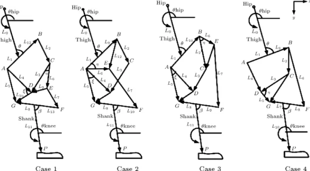
Figure 2. Dierent types of a six-bar knee linkage: (a) Case 1; (b) Case 2; (c) Case 3; and (d) Case 4.
X
M = xB=G4By+ yB=G4Bx+ xD=G4Dy
yD=G4Dx= JG44; (9)
X
Fx= Fh Dx+ Cx= m3aG6x; (10)
X
Fy= Fv Dy Cy W3= m3aG6y (11)
X
M = xD=G3Dy+ yD=G3Dx xC=G3Cy
yC=G3Cx+ xT=G3Fv yT=G3Fh=JG33: (12)
Similarly, the other control moments such as MB, MC,
and MDare calculated.
2.1.2. The six-bar knee mechanism
The dierent types of the six-bar linkages are the Watt and Stephenson as shown in Figure 2 including Cases 1 to 4. In this section, only Case 1 equations of a six-bar mechanism are formulated, due to the similarity of the dynamic analysis in these mechanisms. As shown in Figure 3, there are 18 unknown elements, including
1058 N. Ghaemi et al./Scientia Iranica, Transactions B: Mechanical Engineering 23 (2016) 1055{1063
Figure 3. The free body diagrams for Case 1 of a six-bar mechanism.
the reaction forces at the pin joints, the hip moment, and the control moment. By considering the free body diagrams for Case 1 of a six-bar mechanism in Figure 3 and applying the Newton's laws, the control moment MA can be determined as follows:
X
Fx= Hx Bx+ Ax= (mL0+ mL1)aG1x; (13)
X
Fy=Hy+By+Ay W1=(mL0+mL1)aG1y; (14)
X
M =MA+ Mh+ xh=G1Hy yh=G1Hx
+ xA=G1Ay yA=G1Ax+ xB=G1By
+ yB=G1Bx= JG1h; (15)
X
Fx= Bx Cx= m2aG2x; (16)
X
Fy = Cy By W2= m2aG2y; (17)
X
M = xB=G2By yB=G2Bx+ xC=G2Cy
+ yC=G2Cx= JG22; (18)
X
Fx= Cx+ Ex Dx= m3aG3x; (19)
X
Fy = Cy+ Ey+ Dy W3= m3aG3y (20)
X
M =xE=G3Ey yE=G3Ex xC=G3Cy yC=G3Cx
+xD=G3Dy+yD=G3Dx=JG33; (21)
X
Fx= Ax+ Dx+ Gx= m4aG4x; (22)
X
Fy = Ay Dy+ Gy W4= m4aG4y; (23)
X
M = MA xA=G4Ay+ yA=G4Ax xD=G4Dy
yD=G4Dx+ xG=G4Gy yG=G4Gx
= JG44; (24)
X
Fx= Ex Fx= m5aG5x; (25)
X
Fy = Ey+ Fy W5= m5aG5y; (26)
X
M = xE=G5Ey+ yE=G5Ex+ xF=G5Fy
+ yF=G5Fx= JG55; (27)
X
Fx= Fx+ Fh Gx= m6aG6x; (28)
X
Fy = Fy+ Fv Gy W6= m6aG6y; (29)
X
M = xG=G6Gy+ yG=G6Gx xF=G6Fy
yF=G6Fx+ xT=G6Fv yT=G6Fh
= JG66: (30)
By utilizing the same procedure, the required actuator torque, MB, MG, and MF, can be calculated, too.
2.2. Dynamic analysis of the knee mechanisms by using the compliant joint
In this section, the compliant joint should be substi-tuted in the knee mechanism, in order to get the lower actuator torque. The compliant knee mechanisms are the structures that obtain some of their motions from the stored strain energy of the exible members; as a result, the input torque values are reduced. The proper location and the optimum stiness of the compliant joint during design should be determined to achieve the minimum control moment. In order to achieve this goal, the optimization techniques can be used.
2.2.1. The compliant four-bar knee mechanism As shown in Figure 4(a), the joint B is assumed as the compliant joint. Thus, by considering the eect of the torsional torque in Eqs. (3) and (9), the new equations are given as follows:
X
M =MA+ Mh+ xh=G1Hy yh=G1Hx
+ xA=G1Ay+ yA=G1Ax+ xB=G1By
yB=G1Bx KC14(1 4) = JG1h;
Figure 4. (a) The compliant four-bar knee mechanism. (b) The compliant six-bar knee mechanism 1.
X
M = xB=G4By+ yB=G4Bx+ xD=G4Dy
yD=G4Dx+ KC14 (1 4)
= JG44; (32)
where, KC14 is obtained through the optimization
pro-cedures and known as the spring constant. The other equations are similar to the rigid knee mechanism.
The objective function in the optimization prob-lem is dened to minimize the work done by the control moments during the locomotion cycle and expressed as follows:
min F (x) =
n
X
i=1
jMBi(1i 4i)j ; (33)
where, n = 21 is the selected point number in a locomotion cycle. MBi, 1i, and 4i are the input
control moment on the joint B, the angular positions of the link 1 and link 2 during the gait cycle, respectively. 2.2.2. The compliant six-bar knee mechanism
As shown in Figure 4(b), for Case 1 of the six-bar knee mechanism, the joint G is considered to be the compliant joint. So, by substituting the eect of the torsional torque and putting it in Eqs. (24) and (30) as follows:
X
M = MA xA=G4Ay+yA=G4Ax xD=G4Dy
yD=G4Dx+ xG=G4Gy yG=G4Gx
+ KC46(6 4) = JG44; (34)
X
M = xG=G6Gy+ yG=G6Gx xF=G6Fy
yF=G6Fx+ xT=G6Fv yT=G6Fh
KC46(6 4) = JG66; (35)
and by applying the same optimization procedure and dening the objective function as follows:
min F (x) =
n
X
i=1
jMAi(1i 4i)j; (36)
the proper location and the optimum stiness are obtained. Thus, the spring constants and their appro-priate location are determined by solving the similar equations in other six-bar knee mechanisms.
3. Results and discussion
In this section, the dynamic design curves of the knee mechanisms are shown and their dynamic performance is evaluated.
3.1. The dynamic performance of the rigid knee mechanism
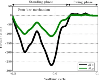
As shown in Figure 5, in a four-bar knee mechanism, the values of MDare signicantly smaller than those of
MB; as a result, the axis D is selected as the best place
for applying the control moment. Figure 6(a) shows the calculated values of MA, MB, MG and MF, in Case 1
of a six-bar. In this gure, MA is the smallest control
moment. So, the axis A is the best location to apply the control moment. In Figure 6(b), MA is smaller
than other control moments; therefore, the joint A is the proper location to exert the control moment. Figure 7(a) shows the minimum control moment at the joint B. From Figure 7(b), it is identied that MG
is the smallest control moment during the gait cycle. Thus, the joint G is the proper location to exert the control moment.
Figure 5. The values of the control moments in a four-bar knee mechanism.
1060 N. Ghaemi et al./Scientia Iranica, Transactions B: Mechanical Engineering 23 (2016) 1055{1063
Figure 6. (a) The values of the control moments in Case 1 of a six-bar knee mechanism. (b) Case 2 of a six-bar knee mechanism.
3.2. The dynamic performance of the compliant knee mechanism
As shown in Figure 8, totally, by using the compliant joint B, the control moment, MD, has been decreased
in a four-bar knee mechanism. In Figures 9 and 10, the control moments, MA, are reduced by adding
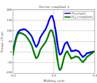
the compliant joint G, Cases 1 and 2 of a six-bar, respectively. Figure 11 shows that the control moment, MB, is considerably decreased when the compliant
joint A is added to Case 3 of a knee six-bar mechanism. From Figure 12 it is observed that the control moment, MG, is decreased by applying the compliant joint G in
Case 4 of a six-bar.
As shown in Table 1, the optimum values for the torsional stiness of the joints have been determined. Moreover, the values of the stored energy have been calculated in the dierent knee mechanisms. From Table 1, it is conrmed that the dynamic performance
Figure 7. (a) The values of the control moments in Case 3 of a six-bar knee mechanism. (b) Case 4 of a six-bar knee mechanism.
Figure 8. The values of the control moments in the compliant four-bar knee mechanism.
Table 1. Results of the compliant mechanisms. Types of
the knee mechanisms
Rigid: the absolute magnitude
of the maximum torque (N.M)
The compliant
joint
Compliant: the absolute magnitude
of the maximum torque (N.M)
Spring constant (N.M/Rad)
Percent of the stored energy (%)
Four-bar 112 B 72 124.57 17.5
Six-bar Case 1 443 G 280 91.76 21.34
Six-bar case 2 153 G 112 324.7 17
Six-bar Case 3 167 A 102 205.96 25
Six-bar case 4 175 G 168 28.5 11.61
Figure 9. The values of the control moments for Case 1 of the compliant six-bar knee mechanism.
Figure 10. The values of the control moments for Case 2 of the compliant six-bar knee mechanism.
of the six-bar knee mechanisms in Case 3 is better than that of the other six-bar knee mechanisms, due to the more stored energy during the locomotion cycle (the percent of the stored energy = 25). In the same design conditions, a four-bar knee mechanism is better than a six-bar knee mechanism, due to the smaller control moments.
Figure 11. The values of the control moments for Case 3 of the compliant six-bar knee mechanism.
Figure 12. The values of the control moments for Case 4 of the compliant six-bar knee mechanism.
4. Conclusion
Since the energy requirements of the prosthetic gait in trans-femoral amputees are greater than normal, there is a need for knee design with low energy expenditure. Therefore, the main objective of this study was to develop a rigid knee mechanism by adding a compliant
1062 N. Ghaemi et al./Scientia Iranica, Transactions B: Mechanical Engineering 23 (2016) 1055{1063
member which would provide the optimal design of the knee prosthesis. The compliant joints were employed in dierent knee mechanisms in order to store more energy and nally reduce the energy consumption of amputees. To achieve this goal, instead of using the experimental methods, an optimization procedure was applied to get the optimum values that resulted in a dynamic pattern resembling the normal locomotion. From the obtained results, it is obvious that control moments are signicantly reduced by utilizing compliant joints on the knee mechanisms. So, the improved performance of the compliant knee mechanism is accomplished through the reduced friction, actuator torque, weight, and maintenance cost.
References
1. Waters, R.L. and Mulroy, S. \The energy expenditure of normal and pathologic gait", Gait & Posture, 9(3), pp. 207-231 (1999).
2. Shandiz, M.A., Farahmand, F., Osman, N.A.A. and Zohoor, H. \A robotic model of transfemoral am-putee locomotion for design optimization of knee con-trollers", Int. J. Adv. Robotic Sy., 10(161) (2013). 3. Radclie, C.W. and Deg, M. \Biomechanics of knee
stability control with four-bar prosthetic knees", in Proc. ISPO Australia Annual Meeting (2003). 4. Radclie, C. \Four-bar linkage prosthetic knee
mech-anisms: kinematics, alignment and prescription crite-ria", Prosthetics and Orthotics International, 18(3), pp. 159-173 (1994).
5. Torfason, L. and Hobson, D. \Computer optimization of polycentric prosthetic knee mechanisms", in Pro-ceedings of the Third Applied Mechanisms Conference (1973).
6. Oberg, K. \Knee mechanisms for through-knee pros- theses", Prosthetics and Orthotics International, 7(1), pp. 107-112 (1983).
7. Kim, K.J., Wu, C.D., Wang, F. and Wen, S.G. \The research of the four-bar bionic active knee", Advanced Materials Research, 308, pp. 1988-1991 (2011). 8. Hamon, A. and Aoustin, Y. \Cross four-bar linkage
for the knees of a planar bipedal robot", in Humanoid Robots (Humanoids), 10th IEEE-RAS Int. Conf. on IEEE, Nashwille, TN, pp. 379-384 (2010).
9. Farhat, N., Mata, V., Rosa, D. and Fayos, J. \A procedure for estimating the relevant forces in the human knee using a four-bar mechanism", Computer Methods in Biomechanics and Biomedical Engineering, 13(5), pp. 577-587 (2010).
10. Bergelin, B.J. and Voglewede, P.A. \Design of an active ankle-foot prosthesis utilizing a four-bar mech-anism", Journal of Mechanical Design, 134(6), p. 061004 (2012).
11. Gong, S., Yang, P. and Song, L. \Development of an intelligent prosthetic knee control system", in Electri-cal and Control Engineering (ICECE), Int. Conf. on IEEE, Wuhan, China, pp. 819-822 (2010).
12. Van Oort, G., Carloni, R., Borgerink, D.J. and Strami-gioli, S. \An energy ecient knee locking mechanism for a dynamically walking robot", in Robotics and Automation (ICRA), Int. Conf. on IEEE, Shanghai, China, pp. 2003-2008 (2011).
13. Wells, J.G., Voglewede, P.A. and Rocheleau, D.N. \De-sign for improved trans-tibial prosthetic devices using four bar mechanisms", 29th Mechanisms and Robotics Conference, Parts A and B, ASME, California, USA, pp. 467-473 (2005).
14. Thompson, T.J. \Specication of prosthetic knee kinematic design parameters using a three-position, instant-center specication approach", Int. Conf. on Mechanical Engineering (ASME), Vancouver, British Columbia, Canada, pp. 347-355 (2010).
15. Thompson, T.J. \Graphical synthesis of four bar mech-anisms by three-position, instant-center specication", 36th Mechanisms and Robotics Conference, Parts A and B, ASME, Chicago, Illinois, USA, pp. 715-724 (2012).
16. Bach, T., Evans, O. and Robinson, I. \Optimization of inertia characteristics of transfemoral limb prosthe-sis using a computer simulation of human walking", In Proceedings of the Eighth Biennial Conference of the Canadian Society for Biomechanics, pp. 212-213 (1994).
17. Farahmand, F., Rezaeian, T., Narimani, R. and Dinan, P.H. \Kinematic and dynamic analysis of the gait cycle of above-knee amputees", Scientia Iranica, 13(3), pp. 261-271 (2006).
18. Mohan, D., Sethi, P. and Ravi, R. \Mathematical modelling and eld trials of an inexpensive endoskele-tal above-knee prosthesis", Prosthetics and Orthotics International, 16(2), pp. 118-123 (1992).
19. Peasgood, M., Kubica, E. and McPhee, J. \Stabiliza-tion of a dynamic walking gait simula\Stabiliza-tion", Journal of Computational and Nonlinear Dynamics, 2(1), pp. 65-72 (2007).
20. Suzuki, Y. \Dynamic optimization of transfemoral prosthesis during swing phase with residual limb model", Prosthetics and Orthotics International, 34(4), pp. 428-438 (2010).
21. Zarrugh, M. and Radclie, C. "Simulation of swing phase dynamics in above-knee prostheses", Journal of Biomechanics, 9(5), pp. 283-292 (1976).
22. Chakraborty, J. and Patil, K. \A new modular six-bar linkage trans-femoral prosthesis for walking and squatting", Prosthetics and Orthotics International, 18(2), pp. 98-108 (1994).
23. Jin, D., Zhang, R., Dimo, H.O., Wang, R. and Zhang, J. \Kinematic and dynamic performance of prosthetic knee joint using six-bar mechanism", Journal of Reha-bilitation Research and Development, 40(1), pp. 39-48 (2003).
24. Font-Llagunes, J.M., Pamies-Vila, R., Alonso, J. and Lugrs, U. \Simulation and design of an active orthosis for an incomplete spinal cord injured subject", Proce-dia IUTAM, 2, pp. 68-81 (2011).
25. Mahler, S., Compliant Pediatric Prosthetic Knee, Uni-versity of South Florida (2007).
26. Roetter, A.D., Lusk, C.P. and Dubey, R. \Bistable compliant extension aid for a polycentric prosthetic knee", 33rd Mechanisms and Robotics Conference, Parts A and B, ASME, California, USA, pp. 241-248 (2009).
27. Harrison, D.G., Andrysek, J. and Cleghorn, W.L. \Feasibility and design of a low-cost prosthetic knee joint using a compliant member for stance-phase con-trol", Journal of Medical Devices, 4(2), p. 027541 (2010).
28. Krishnan, G., Rank, R., Rokosz, J., Carvey, P. and Kota, S. \A strength based approach for the synthesis of a compliant nonlinear spring for an orthotic knee brace", 37th Mechanisms and Robotics Conference, ASME, Portland, Oregon, USA, p. V06AT07A033 (2013).
29. Guerinot, A.E., Magleby, S.P. and Howell, L.L. \Pre-liminary design concepts for compliant mechanism prosthetic knee joints", 28th Biennial Mechanisms and Robotics Conference, Parts A and B, ASME, Salt Lake City, Utah, USA, pp. 1103-1111 (2004).
30. Roetter, A.D., Compliant Prosthetic Knee Extension Aid: A Finite Elements Analysis Investigation of Proprioceptive Feedback During the Swing Phase of Ambulation, University of South Florida (2008). 31. Sigmund, O. \On the design of compliant mechanisms
using topology optimization", Journal of Structural Mechanics, 25(4), pp. 493-524 (1997).
32. Wiersdorf, J., Preliminary Design Approach for Pros-thetic Ankle Joints Using Compliant Mechanisms, Brigham Young University (2005).
33. Hamon, A. and Aoustin, Y. \Compliance for a cross four-bar knee joint", 14th Int. Conf. on Climbing and Walking Robots and the Support Technologies for Mobile Machines, Paris, France, pp. 743-750 (2011). 34. Low, K. \Subject-oriented overground walking pattern
generation on a rehabilitation robot based on foot and pelvic trajectories", Procedia IUTAM, 2, pp. 109-127 (2011).
35. Ghaemi, N., Dardel, M., Ghasemi, M.H., Mohammadi, H. and Zohoor, H. \Optimization of six bar knee link-age for stability of knee prosthesis", Majlesi Journal of Mechatronic Systems, 1(4), pp. 38-45 (2013).
36. Vaughan, C.L., Davis, B.L. and O'connor, J.C., Dy-namics of Human Gait, In Human Kinetics Publishers, 2nd Ed., South Africa, Mills Litho, Cape Town (1999).
Biographies
Narjes Ghaemi was graduated at BS level in Me-chanical Engineering, Heat and Fluid, from Babol Noshirvani University of Technology in 2008. In 2013, she received her MS degree in Mechanical Engineering, Applied Design, from the same university. Her favorite research topics include biomechanics, robotics, dynam-ics, and kinematics.
Hassan Zohoor was born in Esfahan, in 1945. He received his PhD from Purdue University, USA, and spent his postdoctoral time at the same university. Currently, he is Distinguished Professor of Mechanical Engineering at Sharif University of Technology, Aca-demician and Rector of Center for Science and Tech-nology Studies of The Academy of Sciences in IR Iran, and also Member of Executive Board of the Association of Academies and Societies of Sciences in Asia. He has been the author or co-author of over 460 scientic papers. He has also supervised over 200 graduate theses. He was President of Shiraz University, and also the founder, president, and developer of principal codes and regulations of Payame Noor University. He has also been the recipient of several honors and awards such as Allameh Tabatabaei, special award of National Elite Foundation, the Award of Distinguished Professor of Iran, and Ross Ade Award at Purdue University, USA.
Hajar Ghaemi was graduated at BS level in Elec-trical and Electronics Engineering from Mazandaran Institute of Technology in 2011. She is currently an MS student of Electronics, and her favorite research topics include bioelectrical.