Graph Computation Models
Selected Revised Papers from the
Third International Workshop on
Graph Computation Models (GCM 2010)
Generating Instance Graphs from
Class Diagrams with Adaptive Star Grammars
Berthold Hoffmann, Mark Minas
20 pages
Guest Editors: Rachid Echahed, Annegret Habel, Mohamed Mosbah Managing Editors: Tiziana Margaria, Julia Padberg, Gabriele Taentzer
Generating Instance Graphs from
Class Diagrams with Adaptive Star Grammars
Berthold Hoffmann1, Mark Minas2
Universit¨at Bremen Postfach 330 440 28344 Bremen, Germany
and
Fachgebiet Sichere Kognitive Systeme DFKI Bremen
Enrique-Schmidt-Str.5 28569 Bremen, Germany
Universit¨at der Bundeswehr M¨unchen 85577 Neubiberg, Germany
Abstract: In model-driven software engineering, class diagrams are used to define the structure of object-oriented software and valid object configurations, i.e., what objects may occur in a program and how they are related. Object configurations are essentially graphs, so that class diagrams define graph languages. Class diagrams are declarative, i.e., it is quite easy to check whether a graph is an instance of a class diagram. Graph grammars, on the other hand, define a graph language by derivation and are thus well suited for constructing instance graphs. This paper describes how a class diagram can be translated into a graph grammar that defines the same graph language as the original class diagram. Such a graph grammar may then be used for, e.g., automatically generating valid object configurations as test cases. In contrast to earlier attempts, the presented approach allows to translate class diagrams with arbi-trary multiplicities, unique and non-unique associations, composition associations, class generalization, association subsetting and redefinition. This is made possible by using adaptive star grammars, a special kind of graph grammars.
Keywords:Class diagram, Graph grammar, Adaptive star grammar
1
Introduction
The model-driven design of software relies on the precise specification of models, often with diagrams in theuniform modeling language,UML. Class diagrams are the sub-language ofUML
and each link corresponds to a directed edge where source and target are used to distinguish the two roles of the (binary) link. The set of all object configurations that are compatible with a class diagram, therefore, corresponds to a language of graphs, i.e., a class diagram specifies a graph language.
It is easy to check whether a given instance graph is compatible with a class diagram. In con-trast, constructing sample instance graphs for a class diagram is rather difficult. This, however, is important to generate test cases for a software model. In [EKT09], graph transformation rules have been used to do this. Here we use an adaptive star grammar [DHJM10,DHJ+06,DHM08] for this purpose. The approach described in [EKT09] supports only restricted meta models (e.g., class diagrams with constraints): it does not distinguishuniquefromnon-uniqueassociations, considers only very restricted association multiplicities, and does not cover composite associa-tions or associaassocia-tions with redefined or subsetted association ends. Adaptive star grammars, as shown in this paper, allow for a fairly straight-forward treatment of all of these concepts. More-over, adaptive star grammars do not need additional control mechanisms like negative application conditions or prioritizing some rules over others by rule layers as it is necessary in [EKT09].
The rest of the paper is structured as follows. We briefly introduce adaptive star grammars in the next section before we recall some properties of UML class diagrams in Section 3. In Section 4, the main part, the rules generating instance graphs of class diagrams are defined, explained, and illustrated with an example. The conclusions (Section5) mention some related and future work.
2
Adaptive Star Grammars
Graph grammars generalize the idea of Chomsky grammars to graphs: A set of rules defines how the graphs of the language can be derived by applying them to a given initial graph.
Node replacement and hyperedge replacement [Eng99] have been studied most thoroughly as grammars for deriving graph languages. Their rules remove a nonterminal node, and attach a replacement graph to its neighbor nodes. The sort (i.e., the label) and the direction of the edge connecting a neighbor to the nonterminal determine completely how the neighbor is attached to the replacement graph; in hyperedge replacement, the number of neighbors is even fixed for every nonterminal. Both formalisms specify context-free compositions of graphs in the sense
of [Cou87]; however, they fail to define even simple languages, such as the class of all graphs.
Adaptive star grammars[DHJM10] overcome these limitations by means of a cloning mecha-nism that allows the neighbors of a nonterminal to be attached to the replacement graph in an arbitrary fashion.
Let us briefly define the concepts needed; for more detailed definitions, see [DHM08] and for a more thorough discussion [DHJM10].
Graphs. Let the setCofsortsbe the disjoint union of finite disjoint sets ˙Cand ¯Cfor labeling nodes and edges, respectively. We distinguish a subsetN⊆C˙ofnonterminal names.
Agraph G=hG˙,G¯,sG,tG,`˙G,`¯Giconsists of finite sets ˙Gand ¯Gofnodesandedges,
respec-tively, source andtarget functions sG,tG: ¯G→G˙, and functions ˙`G: ˙G→C˙ and ¯`G: ¯G→C¯
assigning a sort to each node and edge, respectively. A node x∈G˙ is called nonterminal if
For a nodexinG, the subgraph consisting ofxand its adjacent nodes and incident edges is denoted byG(x). Aborder node of xis a node in ˙G(x)\ {x}. Note that graphs may have several edges with the same source and target; such edges are calledparallel. Parallel edges with the same label are calledindistinguishable. In the following, we assume that the reader is familiar with common graph terminology, such as subgraph, disjoint union and isomorphism.
Rules and Replacement. Adaptive star grammars are based upon a simple kind of graph trans-formation that replaces a subgraphG(x)by another graph. For this, define arule r=hy,Rito be a pair consisting of a graphRwith a distinguished nodey∈R˙. We callR(y)andR\ {y}the left-and right-hleft-and side ofr, respectively.
LetGbe a graph with a nodex∈G˙ such thatG(x)∼=gR(y)for some isomorphismg. Then the graphH=G[x/gr]is obtained from the disjoint union ofGandRby identifyingR(y)withG(x)
according to the isomorphismgand removingxand its incident edges.
Multiple Nodes. To make graphs (and rules) adaptive, we distinguish a subset ¨G⊆G˙ of ter-minal nodes in a graphGasmultiple nodes, similar to the set nodes of Progress [SWZ99]. A multiple nodex represents any number of ordinary nodes, which are calledclones of x. (The nodes ˙G\G¨ are calledsingular.) In figures, a multiple node is distinguished by drawing it with double lines (see Example1below). A graph that does not contain any multiple node is said to besingular. Note that nonterminal nodes are always singular.
Cloning. LetG be a graph. A function ρ: ¨G→N is a replicator for G. The graph Gρ is obtained from Gbycloning each nodex∈G¨ according toρ, by replicating xand its incident edgesρ(x)times. Ifρ(x) =0, thenxand its incident edges are simply deleted.
Adaptive Star Grammars. Call a graph simple if it contains neither adjacent nonterminal nodes nor indistinguishable edges. A graph of the formG(x)is astarif it contains neither loops nor indistinguishable edges,xis nonterminal and its border nodes are terminal. Anadaptive star rule over Cis a ruler=hy,Ri, whereRis a simple graph with sorts inC, andR(y)is a star. A
clone of r is a rulehy,R0i such thatR0 is simple, and there is a replicatorρ forRsuch that R0
can be obtained fromRρby identifying some of the border nodes ofywith each other (where, of
course, only nodes of the same sort can be identified).
Anadaptive star grammar(ASG) is a systemΓ=hC,P,Zi, wherePis a finite set of
adap-tive star rules, andZ is the initial star, which has no multiple border nodes. (All sorts are taken fromC.) Given a graphG, we writeG=⇒P HifH=G[x/r]for some nodex∈Gand a cloner
of an adaptive star rule inP. Theadaptive star languagegenerated byΓis the set of all terminal
graphsGthat can be derived fromZ:
L(Γ) ={G|Z=⇒+P Gand ˙`G(x)∈C˙\Nfor allx∈G˙},
where=⇒+
P denotes the transitive closure of=⇒P.
Alate replicatorρ¨: ¨G→N×Nsends multiple nodes to pairs of numbers that represent the numbers of singular and multiple nodes that shall be made of a multiple node, respectively. The graphGρ¨ contains, for every multiple nodex∈G¨ with ¨ρ(x) = (n,m),n+mclones, whereofm
are designated as multiple.
In order to apply an adaptive ruler=hy,Rito a graphGwith late cloning, a combined late replicator ¨ρ:G(x)∪R(y)→N×Nis used to clone bothGandr so thatG(x)ρ ∼=R0(y) where
R0 is simple and obtained fromRρ by identifying some of the border nodes ofy. A step using
late cloning is denoted asG⇒P H again;H is obtained by applyinghy,R0itoGρ. Like early
cloning, late cloning does not restrict the language of singular graphs generated by an adaptive star grammar [DHJM10].1
Example 1 (The Language of Unlabeled Graphs) As an example, consider the adaptive star grammarΓwhich is given byΓ= (C,P,Z), whereC˙={ε,A},C¯={λ},Z= A, and
P=
A ::= A , A ::= A , A ::=
.
A rulehy,Riis drawn aslhs::=rhswherelhs=R(y)andrhs=R\ {y}. The grammar derives arbitrary graphs without loops over the sortsε andλ, which are not drawn, that is, the class of
finite unlabeled graphs. Starting withZ, the first rule makes it possible to add an arbitrary number of border nodes. The second rule adds edges between border nodes, and the third removes the nonterminal node.
Let us briefly discuss a major difference between the definition of adaptive star grammars used here and the one in [DHJM10]. The definition of stars and star rules used here is more general since stars are allowed to have parallel (but no indistinguishable) edges which is not allowed
in [DHJM10]. Moreover, cloning a star ruler=hy,Riprior to application may involve taking
a quotient that identifies border nodes ofyinRρ with each other like in [DHM08]. This may
sound alarming, as it was shown in [DHJ+06] that quite a similar type of adaptive star grammars can generate all recursively enumerable languages. However, note that the resulting graph R0
– after cloning and taking the quotient – must be simple. In particular, R0 must not contain indistinguishable edges. The effective rulehy,R0i, therefore, has simple left-hand and right-hand sides. As a consequence, adaptive star grammars of the sort defined above can be simulated by ordinary ones (i.e., those in [DHJM10]) by using subsets of ¯Cto label edges in stars (without parallel edges) and turning every rule into a finite number of rules (corresponding to the allowed quotients). The definition used here just simplifies writing star grammars without extending their power.
3
Class Diagrams
Class diagrams are a well-known graphical language of the UML. The focus of this paper is on the specification of graphs without attributes. Hence, we ignore method and attribute
tions within classes. They can be easily added if required. Moreover, we ignore associations with cardinality greater than 2.
The class diagrams used in this paper consist of classes and (binary)associations between them. Concrete classes are distinguished fromabstract classes. The former are drawn as rect-angles with white background, the latter with gray background and italic class names. Each association has a name and is drawn as a directed edge in order to distinguish the association end-points.2 Each end-point of an association is equipped with a multiplicityof the form u..v
whereu∈N0is the lower bound andv∈N∪ {∗}the upper bound such thatu6vifv∈N. As usual in this context,∗stands for “infinity”. An association may be declaredunique(the default) ornon-unique, indicated by the annotation ’{non-unique}’. We distinguishregularassociations (the default) fromcompositeassociations. The latter have a black diamond at one of their end-points. The multiplicity at this end-point is either 0..1 or 1..1. The class at the end-point with the diamond is calledcomposite, the class at the other end-point is called itspart. Edges represent-ing composite associations are always directed towards the part class, and they may be loops. However, no object can be part of two objects, and no object is (directly or indirectly) part of itself. Moreover, class diagrams may containgeneralizationarrows, which have triangular arrow heads and point from sub-classes to super-classes. Each class may have an arbitrary number of sub-classes and super-classes. However, generalization arrows are not allowed to form cycles. We usually extend the notion of sub-classes and super-classes to all classes that are reachable by chains of generalization arrows (including chains of length 0). We also adopt features of UML 2 and allow association ends toredefineorsubsetother association ends. These features are explained in Sections4.4and4.5.
A class diagram specifies graphs by the mechanism of instantiation: A node is aninstanceof a class iff it is labeled with the class name. Note that each node is an instance of exactly one class. A more general concept is defined as follows: A node is calledmemberof a classC iff the node is an instance ofCor any of its sub-classes. An edgeeis aninstanceof an association from a classC1to a classC2ifeis labeled with the association label, and if the source and target nodes are members ofC1andC2, respectively. Moreover, each association defines amultiplicity
constraint: Letabe an association from classC1to classC2with multiplicitiesu..vat its source
end-point and multiplicityr..sat its target end-point. The multiplicity constraint ofais satisfied iff no member ofC1 has less than r or more thans outgoing a-instances as edges and if no
member ofC2has less thanuor more thanvincominga-instances as edges.
The graph language specified by a class diagram consists of all graphs that satisfy the follow-ing conditions:
C1: Each node is an instance of a concrete class, and each edge is an instance of an association.
C2: The multiplicity constraints of all associations are satisfied.
C3: No two instances of any unique association are indistinguishable edges.
C4: The subgraph induced by composite edges (i.e., instances of composite associations) must
be a collection of trees.
2These directed edges should not be confused with navigation arrows, which solely represent implementation issues
Such graphs are called instance graphsin the following. This definition follows the UML specification when nodes are considered as objects and edges as links [OMG].
4
An Adaptive Star Grammar for Instance Graphs
In the following, we assume an arbitrary, but fixed class diagram. We first describe how this class diagram can be translated into an ASG defining the same graph language. The set of terminal node sorts, hence, must consist of the names of all concrete classes. The set of edge sorts must contain all association names, but also additional edge sorts that will be used for labeling edges between nonterminal and terminal nodes. These edge sorts, but also nonterminal nodes sorts, will be introduced as needed in the following.
The idea of translating a class diagram into an adaptive star grammar defining the same graph language is to start from a graph (calledactual initial graph, AIG, in the following) that closely resembles the class diagram. We add an initial rule that derives the AIG from the initial star that consists of just a single node with a unique nonterminal label. For each concrete class, the AIG contains a multiple node labeled with the class name. Cloning these nodes in a derivation creates the instances of the corresponding classes. The AIG’s other nodes are nonterminal nodes repre-senting the associations of the class diagram: Eachregularassociation is represented by a single node with a unique nonterminal label. It is connected to all multiple nodes of those concrete classes that participate in the association, possibly by being a sub-class of a class at an endpoint of the association. A set of rules is responsible for eventually creating all edges representing instances of the association, i.e., links between objects. The rules make sure that conditionsC2
andC3(see Sect. 3) are satisfied. The construction is more complicated forcomposite
associa-tions since it must make sure that conditionC4is not violated. Actually, each maximal connected
subgraph of the class diagram consisting of composite associations and generalizations only has to be represented by a nonterminal node with a unique label. Rules must be defined that create all possible trees consistent with the class diagram.
These constructions are described in the following. But first, we introduce some notation that makes drawing of rules easier: In rules, corresponding nodes of the left- and right-hand sides are associated by their positions in the drawing. Terminal nodes in rules are always unlabeled; on the left-hand side of a rule, they match terminal nodes with arbitrary labels. Because none of the following rules introduces new terminal nodes on the right-hand side (new terminal nodes are rather created by cloning), there is no need for labeling them. Finally, we use a simplified notation for bundles in graphs as shown in the following illustration: For edge labelsa1, . . . ,an,
bundle (a) is drawn as (b), and as (c) ifa1=· · ·=an=x.
A
· · ·
a1 · · · an
a1 · · ·
an
A
· · ·
A
x
(a) (b) (c)
discuss the construction for composition associations, and finally present an example.
4.1 Non-Unique Regular Associations
Consider an association
U r..s u..v W
{non-unique}
c wherer,s,u,v∈N0,r6s,u6v
within the class diagram. ClassesUandWmay be arbitrary classes,UandWmay even reference the same class, orUmay be a sub-class ofWor vice versa. We assume the upper boundssandv
to be finite, i.e., different from “∗”. However, the following construction can be extended easily to the cases=∗and/orv=∗as we will discuss briefly at the end of this subsection.
LetUandWbe the sets of concrete sub-classes ofUandW, respectively. Note thatUandW contain the classesU andW, respectively., if they are concrete. Note also thatU∩Wcontains all concrete classes being sub-classes of bothU andW. Each instance of a class inU\W has
u..v outgoing, but no incoming c-edges, each instance of a class in W\U hasr..s incoming, but no outgoingc-edges, and each instance of a class inW∩Uhasu..voutgoing as well asr..s incomingc-edges. Since the association is non-unique, indistinguishablec-edges are permitted. The following construction assures these properties.
Let{U1, . . . ,Uk}=U\W,{W1, . . . ,Wn}=W\U, and{V1, . . . ,Vm}=U∩W. Note that each of these sets may be empty. LetC be a nonterminal label that is unique for thisc-association, and let{x0,x1, . . . ,xv} ∪ {y0,y1, . . . ,ys}be a set of pairwise distinct edge labels. The AIG must
contain the following graph as a subgraph:
U1 .. .
Uk
V1 · · · Vm
C
W1 .. .
Wn x0
x0 y0
y0
The meaning of the edges labeledxk andyi is the following: An xk-edge connectsCwith a
terminal node that has k outgoingc-edges already, and anyi-edge connectsC with a terminal
node that has iincomingc-edges already. Note that terminal nodes with labels in W∩Umay have incoming as well as outgoingc-edges; they may even havec-loops where each loop counts as an incoming and as an outgoing edge. The number of incoming and outgoing edges of terminal nodes with labels inW∩Uis indicated by two edges labeledxkandyi, respectively.
We may add anotherc-edge between two appropriate nodes where the source node must have
k<v outgoing c-edges and the target node i<s incoming c-edges. This is the task of the following set of rulesrCk,i, 06k<vand 06i<s, which add a newc-edge between two nodes and increment the “counters” realized by edge labels.
x0 .. .
xv
y0 .. .
ys C
xk yi
rCk,i
::= x0 .. .
xv
y0 .. .
ys C
xk+1 yi+1
Note that such a rule can also be applied in situations where nodes are connected with two parallel edges labeledxk andyi. The corresponding border nodes have to be identified in such
cases. Ac-loop is added if the two singular border nodes are identified.
We can stop adding c-edges if there is noxk-edge and noyi-edge withk<uandi<r; we
can then remove the nonterminal nodeCrepresenting the association. This is realized by the following final rule ˆrC:
xu
.. .
xv
C ... yr
ys
ˆ
rC
::= xu
.. .
xv
.. .
yr
ys
The presented construction uses the fact thatvandsare finite numbers and different from *. The construction, however, is extended easily to the casev=∗and/ors=∗. Let us assume just
v=∗. The new meaning of an xu-edge connectingCwith a terminal node is that the terminal
node hasat least uoutgoingc-edges already. And we change rulerCu,i, so that it no longer creates a newxu+1-edge, but anxu-edge again. It is clear that this construction now creates any number
of outgoingc-edges, but at leastu, at appropriate nodes.
4.2 Unique Regular Associations
We now consider the slightly different situation with auniqueinstead of anon-unique associa-tion; the other aspects remain unchanged.
Let C and ¯C be two nonterminal labels that are unique for this c-association, and let
{x,y0,y1, . . . ,ys}be a set of pairwise distinct edge labels. The AIG must contain the following
graph as a subgraph:
U1 .. .
Uk
V1 · · · Vm
C
W1 .. .
Wn x
x y0
y0
The meaning ofyi-edges is the same as in the previous section, i.e., a terminal node connected
toCwith ayiedge means that the terminal node hasiincomingc-edges already. However, we
do not count outgoingc-edges. Instead, anx-edge between a terminal node andCmeans that the terminal node has not yet any outgoingc-edge.
Since indistinguishablec-edges are prohibited, we cannot createc-edges independently from each other like in the previous subsection. Instead, we use rules that create all outgoingc-edges of any singular node in a single derivation step; anx-edge visits those terminal nodes that receive a bundle of outgoingc-edges to pairwise distinct nodes visited byyi-edges. We define a rulerC
that selects one singular node visited by an x-edge and some of the terminal nodes visited by
“counters” realized byyi-edges:
y0
· · · ys
y0 .. .
ys−1
C x
rC
::=
y0
· · · ys
y1 .. .
ys C
¯
C x
x y
The rule adds a new nonterminal node labeled with ¯C. The following set of rulesrCk¯,u6k6v, adds a bundle ofcedges from the node visited by thex-edge to theknodes visited by they-edges.
¯
C ... ... x
y
y
knodes r
¯
C k
::= ... ...
c
c
Finally, we can remove theC-node as soon as all terminal nodes connected toCwith anx-edge have been processed by rulerC. This is the task of rule ˆrC:
.. .
yr
ys C rˆ
C
::= ...
Like in the previous subsection, these rules use the fact that the upper multiplicity boundsv
andsare finite and different from *. The cases=∗can be realized similarly to the discussion at the end of the previous subsection. As an example, see Sect.4.7. The casev=∗is even simpler: The set of rulesrCk¯ is replaced by a single rulerC¯that looks likerCu¯+1; however, one of the border nodes visited by any-edge is turned into a multiple node. Hence, this rule can add bundles with an arbitrary number ofc-edges, but at leastu.
4.3 Composite Associations
With the constructions of the last two subsections, each class diagram whose associations are all regular can be translated into an adaptive star grammar defining the same graph language. Com-posite associations are special since subgraphs induced by comCom-posite edges must be collections of trees (conditionC4 in Sect.3). The ASG, hence, must be able to create all such trees. In
order to translate this part of a class diagram into an ASG, we have to find those classes whose instances can belong to the same tree. This is done by finding the largest connected subgraphs of the class diagram that contain only composite associations and generalizations. The instance nodes of the classes that belong to the same connected subgraph may, but need not, belong to the same tree. This can be represented in the ASG in the following way: We add a new nonterminal node to the AIG for each of these connected subgraphs, and connect this nonterminal node to each multiple node representing a concrete class within the subgraph. Then we define star rules that create all possible trees consistent with the class diagram.
connected subgraph.
U u..v 0..1 W
c whereu,v∈N0,u6v
Again, classesU andW may be arbitrary classes,U andW may even reference the same class, orUmay be a sub-class ofW or vice versa.
Let the setsU,W,{U1, . . . ,Uk}=U\W,{W1, . . . ,Wn}=W\U, and{V1, . . . ,Vm}=U∩W be defined as in the beginning of Sect.4.1. LetC,C¯ be two nonterminal labels that are unique for thisc-association, and letx,y,zbe distinct edge labels. The AIG must contain the following graph as a subgraph:
U1 .. .
Uk
V1 · · · Vm
C
W1 .. .
Wn x
y z
The nonterminal nodeCstands for all trees with instances of classes inU∪Was nodes connected byc-edges; z-edges visit those terminal nodes (roots) that will “receive”u..v outgoing, but no incoming c-edges. Nodes visited by y-edges (inner nodes) will “receive” u..v outgoing and possibly one incomingc-edge. Finally, nodes visited byx-edges (leaves) will “receive” at most one incoming, but no outgoingc-edge. These properties are assured by the following rules.
C x y
z
z
rC
::=
¯
C
C
C x z y
x
y z
x
y z
C rˆ C
::= hi
The recursive rulerC selects a singular root (visited by az-edge) and recursively proceeds with the rest of the roots by adding a newC-node connected to the multiple node representing the rest of the roots. Moreover, rC creates a ¯C-node that will be derived by a rulerCk¯,i (see below) to a bundle ofc-edges from the root to its children. Those children that are inner nodes become roots of sub-trees, indicated by the other createdC-node. The recursion stops as soon as all nodes have been processed, represented by rule ˆrC, which replaces aC-node by the empty graphhi.
The rulesrCand ˆrCmake sure that each member ofU receives an incomingc-edge. However, this is actually not required by the association. Rule ¯rC, therefore, allows to turn any inner node into a root and any leaf into a singleton tree node. This rule must be dropped if the multiplicity of associationcis 1..1 instead of 0..1 at the composite end-point.
C x
x
y
y
z r¯C
::= C
x
z
Finally, ¯C-nodes must be derived to bundles ofu..vmanyc-edges. This is the task of the set of rulesrCk¯,ifor alli,k∈N0so thatu6i+k6v:
inodes
..
. ...
¯
C z x
x
y
y
knodes
rC¯ k,i
::= ... ...
c
c
c
c
Note that this construction can be easily extended to the situation wherev=∗. The set of rules
rCk¯,i must be replaced by the set of rules rk0C¯ such that 06k6u; rk0C¯ looks likerCk¯+1,u−k+1, but two of the border nodes, one being visited by anx-edge, the other with any-edge, are turned into multiple nodes. Hence, these rules can add bundles with an arbitrary number ofc-edges, but at leastu.
4.4 Class Diagrams with Redefining Associations
Class inheritance, i.e., classes that are specializations of others, is one of the original object-oriented concepts. UML 2 [OMG] has extended class diagrams by the concept of specialization for associations. In this paper, we considerredefinitionandsubsetting. The former is described in this section, the latter in the following.
The following class diagram shows an example of a redefined association end.
U W
X Y
r..s c u..v
¯
r..s¯ d u¯..v¯
{redefinesc.tgt}
An end of an associationccan be redefined by an end of an associationdifdis a specialization ofc, i.e., the associated classes must be compatible. This is indicated by the dashed generaliza-tion arrows, meaning thatX has to be a sub-class3ofUandY a sub-class ofW. The constraint
{redefinesc.tgt}marks the redefining association end and declares the redefined association end, here the target end ofc. A role name would be used in regular class diagrams. In this paper, we ignore role names and, usesrcortgtinstead.
The meaning of redefined associations is as follows: Associations with their ends correspond to class properties that describe links from objects to objects at the other association ends. Re-definition of association ends actually restricts what objects may be linked. As specified by associationc, each instance of classU and its sub-classes may be linked to instances of class
W or its sub-classes. In particular, instances of X (and its sub-classes) may be linked toW -objects by associationc. The redefinition ofc.tgtmeans that eachW-object being linked from an
X-object by associationCmust actually be aY-object. TheseY-objects are directly accessible through associationd; eachd-link is ac-link at the same time. Note, however, that the source end ofddoes not redefine the source end ofcin our class diagram. This means thatU-objects 3 As introduced in Section 3, we extend the notion of sub-classes to all classes that are reachable by chains of
which are notX-objects may still link toY-objects. If the source end ofd were annotated with
{redefinesc.src}, onlyX-objects would be allowed to be linked toY objects by associationc. In the following we show how the situation presented in the class diagram shown above can be translated into an ASG such that the links in each instance graph comply with the association end redefinitions. We will consider non-unique associations only. Unique associations or multiple redefined association ends can be translated analogously.
Translation of redefinition semantics to ASGs is actually simple. The scheme for setting up an ASG for the given class diagram is the same as described in Section4.1. We handle associations
c andd as if they were completely independent associations. Forc, however, we have to set up the AIG in a more restricted way such that noc-edges can be created betweenX-nodes and
Y-nodes. This can be simply enforced by removing each concrete sub-class ofX from setUfirst and then by proceeding as described in Section4.1.
Note that we use edge labeldfor representing links of associationd, which arec-links at the same time. This information is implicit and cannot be represented in instance graphs explicitly.
4.5 Class Diagrams with Association Subsetting
Subsetting of association ends is another extension to associations that has been introduced by UML 2. If an association end may redefine another association end as shown in the previous section, it may also subset it instead. Subsetting association ends do not restrict the subsetted as-sociations, in contrast to redefining association ends. A subsetting association end simply means that each link of the subsetting end must be a link of the corresponding subsetted association end, too. It is easy to see that subsetting one end of an association automatically implies the sub-setting of the other association end. Therefore, we rather say that an association subsets another association instead of association ends subsetting other association ends (as done in the UML standard [OMG]).
The following class diagram shows the general situation of an associationcwhich is subsetted by the associationsd1,d2, . . .dn. The classes at the association ends must be compatible toUand W, respectively, indicated by the dashed generalization arrows.
U W
X1 Y1
Xn Yn
. .. . ..
r..s c u..v
r1..s1 d1 u1..v1
{subsetsc}
rn..sn dn un..vn
{subsetsc}
Similar to the previous section, we are going to represent dt-links by dt-edges. Subsetting
means that each of thesedt-links is ac-link at the same time. Again, this is implicit information
that cannot be represented in the instance graph explicitly. Also similar to the previous section, we consider non-unique associations only. Unique associations can be translated analogously.
Since subsetting associations do not restrict subsetted associations, we can createc-edges and
it as ac-edge, too, since eachdt-link is also ac-link. Counting is necessary if multiplicity is
re-stricted. For instance, if noU-object may be linked to more than twoW-objects using association
c, i.e.,v=2, we must not have anX1-object with one leavingc-edge and two leavingd1-edges.
Similar to Section4.1, we use a nonterminal nodeCfor creating all edges labeledc,d1,d2, . . . ,dn. Cis connected with terminal nodes by edges labeledxkandyiiff the corresponding terminal node
has alreadykoutgoing andiincomingc-edges, respectively. We use edges labeledxtk andyti iff the corresponding terminal node has alreadyk outgoing andiincomingdt-edges, respectively.
The AIG has to containCand one multiple node for each concrete sub-class ofUandW. Nodes representing sub-classes ofXt (t=1,2, . . . ,n) are connected withCbyxt0-edges. Nodes
repre-senting sub-classes ofW andYt (t=1,2, . . . ,n) are connected withCby edges labeled y0 and
yt0, respectively. Note that some classes in the class diagram may actually be the same classes or they may inherit from several classes. The corresponding nodes are then connected withCby several edges.
As an example, we choose n=1, i.e., we have one subsetting association only. Similar to Section4.1, letU,W,X,Ybe the sets of concrete sub-classes ofU,W,X1,Y1, respectively. Note
thatX⊆UandY⊆W. Note also thatU,W,X,YcontainU,W,X1,Y1, respectively, if they are
concrete classes. Each concrete sub-class ofU orW then falls into exactly one of the following sets:
{U1, . . . ,Uk} = (U\X)\W
{W1, . . . ,Wn} = (W\Y)\U
{U11, . . . ,Uk1
1} = X\W {W11, . . . ,Wn1
1} = Y\U {R1, . . . ,Rp} = (W\Y)∩X
{S1, . . . ,Sq} = (U\X)∩Y
{V1, . . . ,Vm} = (U\X)∩(W\Y)
{V11, . . . ,Vm1
1} = X∩Y
and the AIG, therefore, must contain the following graph as a subgraph:
C U11 · · · Uk1
1
R1 · · · Rp
U1 · · · Uk
V1 · · · Vm
V11 · · · V1
m1
W11 · · · W1
n1
S1 · · · Sq
W1 · · · Wn
x0
x10
x1 0
x0
y0
x0
x0 y0
x1 0 y10
x0 y0
y0
y1 0
y1 0
y0
x0
y0
two nodes and increment the “counters” realized by edge labels.
x20
.. .
x2
v2
x10
.. . x1 v1 x0 .. . xv · · · · · ·
y20
.. .
y2
s2
y10
.. . y1 s1 y0 .. . ys C
xk yi
rCk,i
::=
x20
.. .
x2
v2
x10
.. . x1 v1 x0 .. . xv · · · · · ·
y20
.. .
y2
s2
y10
.. . y1 s1 y0 .. . ys C
xk+1 yi+1
c
Analogously, we may add another dt-edge (t=1,2, . . . ,n) between two appropriate nodes
where the source node must havel<vt outgoingdt-edges and the target node j<st incoming dt-edges. However, since eachdt-link is also ac-link, we must count this newdt-edge as ac
-edge, too. Therefore, the source node must havek<voutgoingc-edges and the target nodei<s
incomingc-edges. This is the task of the following set of rules ¯rCt,k,i,l,j (06k<v,06i<s,06
l<vt,06 j<st, and 06t6n) that add a newdt-edge between two nodes and increment the
“counters” realized by edge labels.
x20
.. .
x2
v2
x10
.. . x1 v1 x0 .. . xv · · · · · ·
y20
.. .
y2
s2
y10
.. . y1 s1 y0 .. . ys C xk xt l yi
ytj
¯
rCt,k,i,l,j
::=
x20
.. .
x2
v2
x10
.. . x1 v1 x0 .. . xv · · · · · ·
y20
.. .
y2
s2
y10
.. . y1 s1 y0 .. . ys C
xk+1
xt l+1
yi+1
ytj+1
dt
We can stop addingc-edges anddt-edges if each “counter” has reached its lower multiplicity
bound; we can then remove the nonterminal nodeCrepresenting the association. This is realized by the following final rule ˆrC:
x2u
2 .. .
x2v
2
x1u
1 .. .
x1v
1 xu .. . xv · · · · · ·
y2r
2 .. .
y2s
2
y1r
1 .. .
y1s
1 yr .. . ys C ˆ rC ::= x2 u2 .. . x2 v2 x1 u1 .. . x1 v1 xu .. . xv · · · · · · y2 r2 .. . y2 s2 y1 r1 .. . y1 s1 yr .. . ys
(associationcin our class diagram) that must not be instantiated are declared as{union}. Only their subsetting associations (associationsdt,t=1,2, . . . ,nin our class diagram) may be
instan-tiated as long as these are not themselves declared as {union}. Union-associations can easily be handled in the construction of the grammar by prohibiting the addition ofc-edges, i.e., by dropping the rulesrCk,i.
4.6 Class Diagrams with Empty Graph Languages
There are class diagrams that cannot be satisfied by any instance graph, i.e., its graph language is empty. This section demonstrates that the ASG constructed from such a class diagram has an empty language, too.
As an example, consider the following class diagram.
X
1..1
a
2..2
There is no (finite) instance graph compatible with this class diagram because it requires each instance graph node to have an in-degree of 1 and an out-degree of 2 at the same time.
Of course, the ASG constructed from this class diagram has an empty graph language, too. Each derivation starting from the initial starZ is infinite. Each derived graph contains a non-terminal node; the terminating rules can never be applied. Such a derivation is shown below; every graph whereinnclass nodes satisfy the multiplicity constraints will contain at leastnother classes that do not satisfy it.
Z ⇒
A
X
x0 y0 ⇒
A
X X
x1 y1 x0 y0
a
⇒
A
X X X
x2 y1 x0 y1 x0 y0
a a
⇒
A
X X X X
x2 y1 x1 y1 x0 y1 x0 y0
a a a
⇒
A
X X X
X X
x2 y1 x2 y1 x0 y1
x0 y1
x0 y0
a a
a
a
⇒ · · ·
Interestingly, while there is no finite instance of the class diagram, there are, in fact, infi-nite instances. This fits nicely to the fact that derivation sequences of the ASG are infiinfi-nite and “generate” these infinite graphs.
4.7 Example
Finally, this section presents the rules constructed from an example class diagram and shows the derivation of an instance graph.
con-nected to anE-object. “Manager”-objects of classMare connected to root nodes:
E Node
Child Parent IRoot M
Leaf Inner Root Single
1..∗
f
0..∗ c
1..∗ 1..1 1..1
g
0..1
We assume that the associationfis unique, but thatgis not (which is actually irrelevant for an
m-to-1 association). The associationcis a composite association.
Then the initial rule for the initial starZderiving the AIG looks as follows:
Z ::init=
E
Leaf Inner Root Single
M
G
C F
y0
x0
x y z y0 y0
x
The rules for the compositioncarerC and ˆrC as in Sect.4.3, but without ¯rC since the lower bound of the association at the composite end-point is 1. Because the upper bound at the part end-point is *, we need the following rules for ¯C:
¯
C
x z y
x
r00C¯
::=
c c
c C¯
x zy
y
r0C¯
1 ::=
c c
c
The rules for associationgare constructed as shown in Sect.4.1withr=s=v=1 andu=0:
x0
x1
y0
y1 G
x0 y0
rG
0,0 ::=
x0
x1
y0
y1 G
x1 y1
g
x0
x1
y1
G y1 rˆ
G
::= x0
x1
y1
The rules for associationfare constructed as described in Sect.4.2withr=1,u=0,s=v=∗. Because ofs=∗, rule rF differs from the one shown in Sect. 4.2: any1-edge means that the
connected terminal node has at least one incoming f-edge. Moreover, as discussed at the end of Sect.4.2, there is only a single rulerF¯ creating 0..∗ f-edges from an ¯F-node:
y0 y1
y0
y1 F
x
rF
::=
y0 y1 F
x y1
¯
F
x
F y1 rˆ
F
::= x F¯ y r
¯
F
::= f
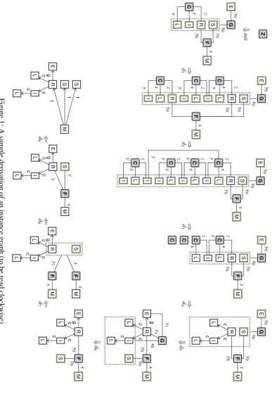
Fig.1shows a sample derivation of an instance graph using these rules. Note that node labels have been abbreviated by initial letters of class names. The derivation arrowsd1, . . . ,d9do not represent single derivation steps, but have the following meaning:d1clones the multipleR-node
to a singular as well as another multiple one, clones theI- and L-nodes three times each, and applies rulerC. d2 clones the topmostI-node to a singular and another multiple one, deletes the
R-,L-, andI-nodes at the bottom (by replicating them 0 times), and appliesrCagain after cloning the remainingI- and L-nodes three times each. d3 deletes the 6 lowermost multiple nodes and
clones the remaining two multipleL-nodes to singular ones. d4 applies ˆrC twice, deleting the isolatedC-nodes, and thenr00C¯ twice after adapting the rule to the context of the corresponding
¯
C-node. d5 appliesr0G,0, andd6applies ˆr
G, deleting theG-node. d
7appliesrF; both theR- and
theS-node get visited byy1-edges.d8deletes the multipleM-node by replicating it 0 times, and applies ˆrF, deleting theF-node. Finally,d9clones theS-node twice and appliesrF¯.
5
Conclusions
We have described how a class diagram can be translated into an adaptive star grammar that defines the same language of instance graphs as the class diagram. The translation process works for all class diagrams with generalizations, and with associations that may be unique, non-unique, or even composite, and may have arbitrary multiplicities. We have explicitly shown the translation process for regular associations with arbitrary multiplicities, have outlined the translation for compositions, and demonstrated the situation for a single composition association. Furthermore, we have shown that newer concepts of class diagrams, like association subsetting and redefinition, can also be translated correctly.
The presented approach closes the gap between class diagrams as a declarative approach for defining instances and graph grammars, which provide a constructive definition. This makes techniques known from graph grammars available to class diagrams as well. For instance, test cases can be constructed automatically by just creating sample derivations. Furthermore, gram-mars allow for inductive definitions based on their rules and their derivation trees that structure instances of the class diagram hierarchically. Moreover, one may wish to restrict the instances of a class diagram in ways that class diagrams cannot express. The translation into an equivalent grammar may make this possible, because grammars allow for a much finer tuning.
The benefits of using adaptive star grammars come with a moderate descriptive complexity. If association subsetting is not used, the size of each rule (by counting nodes and edges on a rule’s left-hand side and right-hand side) depends linearly on the maximum finite multiplicity boundm used in the class diagram, and the number of obtained rules grows linearly with the number of associations and quadratic withm. For class diagrams with association subsetting, the descriptive complexity is worse. LetNsbe the number of associations participating in association
subsetting. Then, the size of rules obtained for such associations depends linearly onmandNs,
whereas the number of rules grows linearly withNsand with the fourth power ofm.
G. Taentzer [BELT04] considerably. In [EKT09], a meta model is translated into a graph gram-mar that defines the same language of instance graphs. In that paper, composite associations are not considered, multiplicities are restricted to the simplest cases, and unique and non-unique associations are not distinguished. Moreover, the generated graph grammar makes heavy use of negative application conditions for specifying forbidden context graphs, and uses a layering mechanism to give some rules priority over others. This does not only complicate the grammar, but—more important—also the reasoning about the grammar and the graph language it gener-ates.On the other hand, this kind of grammar allows to treat some simple meta model constraints by translating them into application conditions.
So far, we have not considered how meta model constraints can be translated along with the class diagram into an adaptive star grammar, possibly with application and graph conditions. A related, but not general approach has been described in previous work [HM10] where rules may be applied only if their application conditions are satisfied. In future work, we intend to make use of generalized results on context conditions and their relation to logical graph properties and constraints by A. Habel and K.-H. Pennemann [HP09] and A. Habel and H. Radke [HR10].
Acknowledgement. We would like to thank the anonymous referees for reading the submitted version carefully, and making valuable suggestions that helped to improve the paper.
Bibliography
[BELT04] R. Bardohl, H. Ehrig, J. de Lara, G. Taentzer. Integrating Meta-modelling Aspects with Graph Transformation for Efficient Visual Language Definition and Model Ma-nipulation. InProc. Fundamental Approaches to Software Engineering (FASE’04). Lecture Notes in Computer Science 2984, pp. 214–228. Springer-Verlag, 2004. doi:10.1007/978-3-540-24721-0 16
[Cou87] B. Courcelle. An Axiomatic Definition of Context-free Rewriting and its Application to NLC rewriting.Theoretical Computer Science55(2-3):141–181, 1987.
doi:10.1016/0304-3975(87)90102-2
[DHJ+06] F. Drewes, B. Hoffmann, D. Janssens, M. Minas, N. V. Eetvelde. Adaptive Star Grammars. In Corradini et al. (eds.),3rd Int’l Conference on Graph Transformation (ICGT’06). Lecture Notes in Computer Science 4178, pp. 77–91. Springer, 2006. doi:10.1007/11841883 7
[DHJM10] F. Drewes, B. Hoffmann, D. Janssens, M. Minas. Adaptive Star Grammars and Their Languages.Theoretical Computer Science411(34-36):3090–3109, 2010.
doi:10.1016/j.tcs.2010.04.038
[EKT09] K. Ehrig, J. M. K¨uster, G. Taentzer. Generating Instance Models from Meta Models.
Software and System Modeling8(4):479–500, 2009. doi:10.1007/s10270-008-0095-y
[Eng99] J. Engelfriet. Context-Free Graph Grammars. In Rozenberg and Salomaa (eds.),
Handbook of Formal Languages. Volume 3: Beyond Words, chapter 3, pp. 125–213. Springer, 1999.
[HM10] B. Hoffmann, M. Minas. Defining Models – Meta Models versus Graph Grammars.
Elect. Comm. of the EASST29, 2010. Proc. 6th Workshop on Graph Transformation and Visual Modeling Techniques (GT-VMT’10), Paphos, Cyprus.
http://www.easst.org/eceasst/
[HP09] A. Habel, K.-H. Pennemann. Correctness of high-level transformation systems rela-tive to nested conditions.Mathematical Structures in Computer Science19(2):245– 296, 2009.
doi:10.1017/S0960129508007202
[HR10] A. Habel, H. Radke. Expressiveness of graph conditions with variables. Elect. Comm. of the EASST 30, 2010. International Colloquium on Graph and Model Transformation (GraMoT’10).
http://www.easst.org/eceasst/
[OMG] OMG. OMG Unified Modeling Language (OMG UML), Infrastructure, Version 2.2.
OMG Document Number: formal/2009-02-04. http://www.omg.org/spec/UML/2.2/Infrastructure
[SWZ99] A. Sch¨urr, A. Winter, A. Z¨undorf. The PROGRES Approach: Language and