HP XP P9000 External Storage for Open
and Mainframe Systems User Guide
Abstract
This guide describes and provides instructions to use HP XP P9000 External Storage software on HP XP P9000 disk arrays. The intended audience is a storage system administrator or authorized service provider with independent knowledge of HP XP P9000 disk arrays and the HP Remote Web Console.
HP Part Number: AV400-96599 Published: January 2014 Edition: Tenth
© Copyright 2010, 2014 Hewlett-Packard Development Company, L.P.
Confidential computer software. Valid license from HP required for possession, use or copying. Consistent with FAR 12.211 and 12.212, Commercial Computer Software, Computer Software Documentation, and Technical Data for Commercial Items are licensed to the U.S. Government under vendor's standard commercial license.
The information contained herein is subject to change without notice. The only warranties for HP products and services are set forth in the express warranty statements accompanying such products and services. Nothing herein should be construed as constituting an additional warranty. HP shall not be liable for technical or editorial errors or omissions contained herein.
Acknowledgements
Microsoft®, Windows®, Windows® HP, and Windows NT® are U.S. registered trademarks of Microsoft Corporation. Export Requirements
You may not export or re-export this document or any copy or adaptation in violation of export laws or regulations.
Without limiting the foregoing, this document may not be exported, re-exported, transferred or downloaded to or within (or to a national resident of) countries under U.S. economic embargo, including Cuba, Iran, North Korea, Sudan, and Syria. This list is subject to change.
This document may not be exported, re-exported, transferred, or downloaded to persons or entities listed on the U.S. Department of Commerce Denied Persons List, Entity List of proliferation concern or on any U.S. Treasury Department Designated Nationals exclusion list, or to parties directly or indirectly involved in the development or production of nuclear, chemical, biological weapons, or in missile technology programs as specified in the U.S. Export Administration Regulations (15 CFR 744).
Revision History
Description Date
Edition
Applies to microcode version 70-01-01-00/00 or later. October 2010
First
Applies to microcode version 70-01-24-00/00 or later. November 2010
Second
Applies to microcode version 70-01-62-00/00 or later. January 2011
Third
Applies to microcode version 70-02-01-00/00 or later. May 2011
Fourth
Applies to microcode version 70-02-5x-00/00 or later October 2011
Fifth
Applies to microcode version 70-03-00-00/00 or later. November 2011
Sixth
Applies to microcode version 70-03-30-00/00 or later. April 2012
Seventh
Applies to microcode version 70-04-00-00/00 or later. August 2012
Eighth
Applies to microcode version 70-06-00-00/00 or later. July 2013
Ninth
Applies to microcode version 70-06-11-00/00 or later. January 2014
Contents
1 Overview...7
Features—multiple systems, common management...7
How External Storage works...7
Typical components...8
External storage system...9
External volume...9
Internal volume...9
License...9
Interfaces ...9
Remote Web Console ...9
RAID Manager...9
Spreadsheets ...10
2 Requirements and planning...11
Planning workflow...11
System requirements...11
Planning considerations for external storage systems...12
Application performance considerations...13
Planning external volumes ...13
Cache use and external storage performance...14
Cache Mode effects with other HP software...15
Mainframe volumes...15
Open systems volumes...16
External volume groups (ExGs) ...16
Capacity requirements for volumes ...16
LDEV capacities per emulation type...17
Example: Determining capacity for OPEN-3 volume...18
Adjusting volume capacities for pairs...19
Planning external paths and path groups ...20
External paths...20
Single path mode...20
Multi path mode ...21
Supported external systems’ path mode for external volumes...22
External path configurations — direct and switch ...23
Default mapping settings...24
3 HP P9500 software supported for external volumes...25
Cache Residency ...25
Snapshot ...25
Thin Provisioning,Dynamic Provisioning for Mainframe, Smart Tiers, and Smart Tiers Z, and Fast Snap...26
Local replication software...26
LUN Manager and Configuration File Loader...26
LUN Expansion ...27
Performance Monitor and Auto LUN V2...27
Remote replication software ...28
SNMP Agent ...28
Customized Volume ...28
4 Setting up external volumes...29
Setup workflow ...29
Setting up ports on the local system...29
Setting up ports on the external system...30
Mapping an external volume...30
Preparing mapped volumes for use...34
Using mapped volumes ...35
Recognizing local system from the external system...35
5 Monitoring and maintenance...36
Monitoring external volumes and paths ...36
Editing external volume policies (settings)...36
Editing mapping policies ...37
Changing external volume processor blade ...38
Changing I/O system for external storage systems...38
Editing external WWN settings ...39
Path maintenance...40
Adding an external path to an existing path group ...40
Changing external path priority ...41
Disconnecting an external path ...41
Reconnecting an external path ...42
Changing the cache mode setting of the external volume...42
Prerequisites...42
Changing the cache mode...42
Removing, replacing an external path ...43
Replacing all external paths ...44
Disconnecting external systems and volumes ...44
Prerequisite requirements...45
Disconnecting an external storage system, all mapped volumes ...45
Disconnecting a single mapped volume ...46
Reconnecting external systems and volumes ...47
Reconnecting an external storage system, all mapped volumes...47
Reconnecting a single mapped volume ...47
Deleting an external volume mapping ...48
Powering off and on local, external storage systems ...49
Requirements for external storage system maintenance...50
Powering off and on the external storage system...50
Powering off and on the local storage system...51
Powering off and on both storage systems...51
6 Support and other resources...52
Contacting HP...52
Subscription service...52
Documentation feedback...52
Related information...52
HP websites...52
Conventions for storage capacity values...53
Typographic conventions...53
General troubleshooting ...54
Troubleshooting external path status...55
Troubleshooting path errors for specific storage systems...57
HP P9500 and HP24000/HP20000 Disk Array...57
HP12000 Disk Array / HP10000 Disk Array...58
HP1024/HP128 Disk Array...58
HP512/HP48 Disk Array...59
Thunder 9500V...59
HUS/AMS/WMS...60
SVS200 ...60
A Supported external storage systems...62
External systems...62
HUS VM Storage System...62
HP P9500...62
HP24000/HP20000 Disk Array...62
HP12000 Disk Array/HP10000 Disk Array ...62
Host mode option for a volume larger than 2 TB...62
HP1024/HP128 Disk Array ...63
HP512/HP48 Disk Array...63
Thunder 9500V...63
Identifying the 9500 V model using the serial number...64
Identifying the controller using the port WWN...64
HUS/AMS/WMS ...64
Identifying the HUS/AMS/WMS model using the serial number...65
Identifying the controller using the port WWN (HUS/AMS/WMS)...66
Identifying logical volumes using Characteristic1...67
Caution on using the power savings option ...67
AMS 2000 series guidelines...67
SVS200 storage system...68
EVA storage system...68
Identifying logical volumes using Characteristic2...68
Sun StorEdge 6120/6320...69
Sun StorageTek FlexLine 380...69
Sun StorageTek 2540...69
Sun StorageTek V2X2...70
EMC CLARiiON CX series...70
System option mode for connecting EMC CLARiiON CX series...70
System parameters for connecting EMC CLARiiON CX series...70
EMC VNX series...70
System option mode for connecting EMC VNX series...70
System parameters for connecting EMC VNX series...71
EMC Symmetrix series...71
IBM DS3000/DS4000/DS5000 series...71
IBM V7000 series...71
IBM SVC series...71
IBM XIV series...72
Fujitsu FibreCAT CX series...72
Fujitsu DX60/80/90 S2 and Fujitsu DX400 S2...72
SGI IS4600 series...73
3Par T800, F400, V800, V400 series...73
Storage system with a product name displayed as "(generic)"...73
Support conditions when product name displays as “(Generic)”...73
Virtualization support requirements...75
Suggested Virtualization Procedure...75
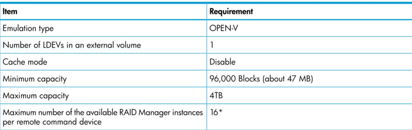
B Remote command devices...76
Overview of remote command devices ...76
Storage systems supported for remote command devices...76
Requirements ...77
Restrictions and other information...77
Mapping a command device ...78
C RAID Manager command reference...80
Remote Web Console Action names and RAID Manager commands...80
D External Storage GUI reference...81
Storage window...81
Selected external storage system window...83
Selected external path group window...85
Add External Volumes wizard ...89
Select External Path Group window...89
Add External Volumes window...90
Discovered External Volumes...90
Selected External Volumes...93
Confirm window...96
Edit Policies window...97
Edit External Volumes wizard...99
Edit External Volumes window...99
Confirm window...100
Edit External Path Configuration wizard...101
Edit External Path Configuration window...101
Confirm window...103
Edit External WWNs wizard...103
Edit External WWNs window...104
Confirm window...105
Delete External Volumes wizard...105
Delete External Volumes window...106
Confirm window...107
Disconnect External Paths wizard...107
Disconnect External Paths window...108
Confirm window...108
Reconnect External Paths wizard...108
Reconnect External Paths window...109
Confirm window...109
Discover External Target Ports window...110
Create External Path Group window...110
Change Settings window...112
View External LUN Properties window...113
Reconnect External Storage Systems window...114
Reconnect External Volumes window...115
Disconnect External Storage Systems window...116
Disconnect External Volumes window...116
Assign Processor Blade wizard...117
Assign Processor Blade window...117
Confirm window...118
External LDEV Properties window...118
Glossary...120
1 Overview
With External Storage, you connect volumes in external storage systems to the HP P9500 and manage them as if they were one system.
This guide provides information and instructions for planning, set up, maintenance, and troubleshooting the use of external volumes with P9500 and its software products.
Features—multiple systems, common management
When a system consists of multiple storage systems, a host must usually be connected to all of the systems. When a system administrator configures the connections from the host to volumes, he or she follows different instructions for each of the storage systems.
With External Storage, the administrator configures the connection from the host to the P9500 storage system, then can manipulate mapped volumes in an external storage system in the same way as volumes in the P9500 storage system.
Operations between storage systems can also involve different procedures. But with External Storage, you perform them with the same HP software as when you use P9500 systems.
For example, you will use the desired HP replication program for copy operations between P9500 and the external systems, including the following:
• Copying data from a volume in HP P9500 to a volume in the external system.
• Copying data from a volume in an external system to a volume in another external system.
How External Storage works
A volume in an external storage system becomes an internal volume in HP P9500 when you map to it.
• A local system port must be connected to the external storage system port with a fibre cable. This route between ports is the "external path".
• The external volume is represented in the HP P9500 as an internal volume, and the path between them is the “mapping path”.
• The figure below shows the connection between the local and external storage systems. In this figure, the external system is connected to the local system’s “external ports” via a switch using the Fibre-Channel interface. An “external port” is an attribute assigned to HP P9500 ports.
Multiple external storage systems can be connected to one external port. You can add an additional external storage system even when the external port is already in use.
NOTE: Mapped external volumes can be accessed and copied by hosts connected to HP P9500, though not by hosts connected to the external systems.
NOTE: Mapped external volumes must be accessed and copied only by hosts that are connected to the P9500, not by hosts connected to the external systems.
Logical devices (LDEVs) are created during or after the mapping operation. If created after mapping, the LDEVs are created in the same way they are when you create normal internal volumes using Virtual LVI/Virtual LUN. As shown in the figure, LDEVs in mapped external volumes are required for use in the local system.
Typical components
External Storage consists of the following components:
• An HP P9500 storage system, referred to as the “local storage system” • External Storage license
• An external storage system
• An external volume mapped to the local system. In the local system, the mapped external volume is referred to as an “internal volume”, and is a virtual representation of the external volume.
• LDEVs (logical devices).
• Remote Web Console, RAID Manager, and/or HP Command Line Interface
• External path
• Mapping path
External storage system
The HP P9500 can connect to other HP storage systems, original equipment manufacturer (OEM) systems, and other vendors' systems (such as IBM or EMC). Hosts recognize volumes in these other systems as “internal volumes” of the HP P9500.
External volume
A volume in the external storage system that is mapped to the local storage system.
Internal volume
A volume managed by the local storage system. An internal volume can be a physical volume or the virtual representation of an external volume.
License
External Storage is an HP software product requiring installation of a license key. See the HP XP
P9000 Remote Web Console User Guide for instructions.
Interfaces
You can perform External Storage operations using the following interfaces:
• Remote Web Console
• RAID Manager
• Spreadsheets
Remote Web Console
The HP graphical user interface used to manage the HP P9500 system and the connected external storage volumes. Remote Web Console is run from a browser on the user-supplied computer. The operations described in this document are performed using Remote Web Console.
RAID Manager
RAID Manager provides a command line interface to perform most of the same operations as Remote Web Console. RAID Manager operations are issued directly from the host, and can be automated using scripts. External volumes can be used as remote command devices.
Spreadsheets
With spreadsheets, you can schedule and perform the following External Storage operations. • Map external volumes with multiple or single LDEVs to the local system
• Retrieve information about mapped external volumes
• Retrieve information about external volume groups configured to the local system • Retrieve information about all SSIDs in the local system
• Disconnect and reconnect an external volume or an external storage system • Delete external volume mapping
• Move an external volumes from one path group to another existing group or to a new group. See HP XP P9000 Spreadsheet Guide for complete information.
2 Requirements and planning
This topic describes requirements and planning.
Planning workflow
Before mapping an external volume to HP P9500, review the information in this chapter to make sure that you understand the External Storage requirements and implementation procedures. Use the general order in the following to prepare for External Storage:
• ReviewSystem requirements (page 11).
• Ensure that the external system whose volumes you want to map is supported by External Storage. See“Supported external storage systems” (page 62).
• Ensure the functionality you want is supported for mapped external volumes. See“HP P9500 software supported for external volumes” (page 25).
• In the external system, select a port and set any necessary parameters. SeeSetting up ports on the external system (page 30).
• In the local system, identify the port that will connect to the external system and make sure it is specified as an “external port”. See “Setting up ports on the local system” (page 29). • Plan data paths from the local to the external system. See“Planning external paths and path
groups ” (page 20).
• In the external system, prepare volumes for use in the local system. For example, if you plan to use an external volume for replication, make sure it matches the HP replication software’s requirements.
See the following for this and other considerations.
◦
“Planning external volumes ” (page 13)◦
“Mainframe volumes” (page 15)◦
“Open systems volumes” (page 16)◦
Capacity requirements for volumes (page 16)• In the local storage system, configure external volume groups to which you will assign the external volume during the mapping operation. SeeExternal volume groups (ExGs) (page 16). • You can change the defaults for some mapping settings before performing the operation. See
Editing external volume policies (settings) (page 36).
System requirements
External Storage (Ext Stor) operations are performed between the local storage system—HP P9500—and volumes in an external storage system. General requirements for these and all Ext Stor components are described below.
Description Item
HP P9500 (HP P9500) • Required for the Ext Stor local storage system. • All hardware and microcode levels must be installed.
One is required, multiple external systems are supported per HP P9500. See Supported external storage systems (page 62)for related details about each supported external storage system.
External storage systems
Description Item
Supported external storage systems are listed on the HP StorageWorks Single Point of ConnectivityKnowledge (SPOCK) website:http://www.hp.com/storage/spock Required. See the HP XP P9000 Remote Web Console User Guide for installation and operations instructions.
Ext Stor license key
As needed. SeeHP P9500 software supported for external volumes (page 25)for HP P9500 software and functions that can be used with external volumes. Other HP P9500 software
licenses
Required. Remote Web Console
External volumes are reported as RAID 1 in the following displays: RAID level
• HP P9500 internal processing. (A bar (-) displays on the Remote Web Console windows.)
• Information about the external storage system that is reported to a higher-level device (OS).
Internally, HP P9500 uses RAID 1 cache management for external volumes. The external storage controller is responsible for physical RAID methods.
Ports in external storage system • Maximum = 1,024 ports can be connected with HP P9500. • (WWN is used as a port identification number)
No. of mapped ext. vols. • Maximum = 63,232 • Maximum per port = 4,096
• For Fast Snap, Snapshot and Thin Provisioning:
Number of external volumes + Number of virtual volumes ≤ 63,232
Maximum = 16,384 No. of ext. vol. groups
Maximum = 4,096 No. of vols. registered in ext. vol.
group
No. of mapping paths • One required
• Two or more recommended • Maximum = 8 per external volume
The minimum capacity of an internal volume changes depending on the emulation type. See“LDEV capacities per emulation type” (page 17)
Minimum capacity of an internal volume
77,760 blocks (about 38 MB). Minimum capacity of an ext. vol.
However, when the emulation type is OPEN-V, the minimum capacity is 96,000 blocks (about 47 MB).
Maximum capacity of an ext. vol. • 59.99TB (128,849,011,200 blocks)
• You can use a volume with more than 59.99TB, but you can only access 59.99TB as a mapped external volume.
• Use Virtual LVI/Virtual LUN to create multiple LDEVs of OPEN-V up to the maximum LDEV size of 3.99 TB each.
Planning considerations for external storage systems
An external storage system’s performance is affected by local system operations; conversely, performance of the host and local system are affected by the attributes assigned to the external system.
Note the following regarding performance:
• Host I/O performance (sequential write performance only) to mapped volumes can be improved by setting SOM 872 to ON. For more information, call the HP Technical Support.
• The performance and status of the external system affect read/write performance of the mapped external volume. A heavy load on the external system slows the processing speed of read/write operations. In this case, I/O from a mainframe host may receive a Missing Interrupt error. • If the host connected to the local storage system issues numerous I/O to be processed by the
external storage system, the commands from the host may time out.
• When you execute HP P9500 software commands that result in more I/O processed than the external storage system can handle, the commands could time out and an error may occur. • When you manipulate an external volume from the host, check the Path Blockade Watch time
for the external volume. If the value for this setting is longer than the timeout period of the host command, the host command may time out when the power supply is off or when an error occurs in the external storage system. If host I/O is a significant concern, make sure that the Path Blockade Watch time of the external volume is the same as or shorter than the timeout period of the host command.
Application performance considerations
Performance requirements for an application can be met when using external storage, but note the following considerations in this regard:
• Internal storage typically provides faster response times than external storage when the storage is of the same type.
• Storage used by the application must have the proper performance characteristics. For example, SATA type storage does not provide the performance requirements usually needed for an OLTP application.
• The mainframe Transaction Processing Facility (TPF) should not use external storage.
Planning external volumes
External volumes must be set up to match External Storage requirements. Note the following: • You can use pre-existing data in an external volume after it is mapped to the local system,
with the following restrictions:
◦
Emulation type must be set to OPEN-V when you map the volume.◦
To perform host I/O operations, an LU path from the Target port to the mapped volume must be set.• An external volume’s maximum or minimum available capacity depends on the emulation type you specify when mapping the volume.
SeeCapacity requirements for volumes (page 16) for more information.
• You cannot access data stored in an external volume beyond the allowed maximum capacity. See “Maximum capacity of an external volume” inSystem requirements (page 11).
• You cannot map an external volume whose capacity is smaller than the minimum capacity required for internal volumes, which is 30 GB.
• Make sure that a mapped external volume is accessed only from the local HP P9500 storage system.
◦
Make sure that a mapped external volume is not accessed from a host that is connected to the external storage system.◦
Make sure that a mapped external volume is not manipulated by a copy function or any other functions of the external storage system.◦
Accessing a mapped external volume from the external storage system requires that the volume mapping be disconnected first.• External volumes that are reserved by a host cannot be mapped as internal volumes. To map these volumes, cancel the reserve settings, remove host access to the volumes, and then perform the mapping operation.
• Do not map multi-platform volumes of external storage systems as internal volumes.
• When an external storage system that uses control unit path ownership is connected to the HP P9500, configure the external path to the primary controller in the external storage system as the primary path.
Ownership is the exclusive right to control volumes. A controller that has ownership is called a primary controller. If the external path is connected to a controller that does not have ownership, and the path is configured as primary path, the ownership will be transferred, which may affect performance.
• A management LU cannot be used as an external volume.
A management LU receives commands from an application; it controls or manages the application, and stores control information from the application. An example of a management LU is a Universal Xport LU. (A RAID Manager command device is not a management LU.) Before performing the external volume mapping operation, perform one of the following operations on the external storage system.
◦
Delete the management LU from the port to be connected to the HP P9500.◦
Make sure that at least one LU is used for data storage and has a smaller LUN (LU number) than the management LU’s LUN. Also make sure that the data storage LU is set to the port connected to the HP P9500.◦
Use the security function and configure the access attribute of the management LU to prohibit read and write operations.An external storage system that has a management LU might not be recognized by the local storage system.
Cache use and external storage performance
Performance for external storage used with the HP P9500 is highly dependent on proper cache configuration. The Cache Mode setting, which you specify during the mapping operation, affects external storage performance.
When data is written to the mapped external volume, Cache Mode controls when the write-complete response is sent to the host.
• When Enabled is specified, the write-complete response is sent when the write data is in the HP P9500 cache.
• When Disabled is specified, the write-complete response is sent when the write data is accepted by the external system.
Enabled can adversely impact overall HP P9500 performance if the I/O rate exceeds the
performance capabilities of the external system. If you specify Enabled, you should use the same formula for sizing cache in both the internal and external systems.
A cache partition should be defined when Enabled is used for the Cache Mode setting. A CLPR helps to protect overall HP P9500 performance when the I/O rate tends to exceed the capabilities of the external system.
Cache Mode effects with other HP software
Note the following additional effects regarding theCache Mode setting:
• If you perform the Cache Residency bind mode operation on an external volume, Cache Mode is set to Enabled. In this case, twice as much cache capacity as user data area capacity is required for the operation. (Bind mode is unavailable when Ext Stor Cache Mode is set to Disable.)
• The external volumes in a LUSE must all use the same Cache Mode setting, either Enabled or Disabled.
• The external volumes in a Thin Provisioning pool must all use the same Cache Mode setting, either Enabled or Disabled.
• Smart Tiers pool volumes require Cache Mode to be set to Enabled.
• Data that is not written by the host (for example, data written by Business Copy) is
asynchronously destaged to the external storage system regardless of the Cache Mode setting. • When you set emulation type for a mainframe system, note the following:
Data written by a host using a Format Write command is asynchronously destaged to the external storage system regardless of the Cache Mode setting.
◦
◦
Data written by a host using other Write commands are destaged to the external storage system as configured in the Cache Mode setting.Mainframe volumes
Note the following requirements and considerations for mapping mainframe external volumes: • Make sure that mainframe external volumes on a mainframe operating system consist of at
least one LDEV before mapping.
• When multiple LDEVs exist in an external volume and numerous I/Os are made to them, read/write commands may timeout. When the commands timeout, the SIM (21D2xx) is reported.
• Set the MIH (missing interrupt handler) timer to 45 seconds (which is the recommended value) for mainframe external volumes on a mainframe operating system.
• Pre-existing mainframe volumes on an external system that are accessed by FICON channels cannot be mapped to the local storage system because the HP P9500 does not recognize these volumes
You can prepare mainframe external volumes for mapping using one of the following methods:
◦
Zero-format the external volumes on the external system, map the volumes to the HP P9500, then perform the Write to Control Blocks operation using Virtual LVI/Virtual LUN on the local system side.◦
Map the external volumes to the HP P9500, and then format the mapped volumes on the local storage system using the Virtual LVI/Virtual LUN.NOTE: The following relates to mapped volumes:
◦
After the mapping operation, the status of the mapped volume becomes Blockade; however, after the Write to Control Blocks operation is performed or mapped volume is formatted on the local system, the mainframe host can then access the new mainframe volume through the local HP P9500 system's FICON channels.◦
If you format the mapped volume from the external system, existing data is deleted and there are no options for retaining it. This is the reason for formatting from the local system side, as mentioned above.For information on formatting and the Write to Control Blocks operations, see the HP XP P9000
Provisioning for Mainframe Systems User Guide.
Open systems volumes
Note the following requirements and considerations for mapping OPEN systems external volumes: • OPEN systems external volumes do not require reformatting because the connection between
HP P9500 and the external system is Fibre Channel.
However, if you need to initialize the data area for the volume, format the volume using the Virtual LUN function. See the HP XP P9000 Provisioning for Open Systems User Guide for instructions.
• OPEN-V emulation provides the most efficient use of storage and the best performance. Also, emulation types other than OPEN-V may not retain existing data after being mapped.
External volume groups (ExGs)
During the mapping operation, you assign the external volume to an external volume group. This allows you to organize external volumes used for similar purposes a group or groups.
For example, you may want to assign mapped volumes in the same external system to a specific ExG. Or, you may assign volumes used in a particular function, such as Business Copy/Snapshot or Continuous Access Journal, to an ExG, even if the data is stored in different external storage systems.
You could also use ExGs to correspond to the external system’s physical disk grouping, such as a RAID group.
You assign external volume group numbers during the mapping procedure.
Capacity requirements for volumes
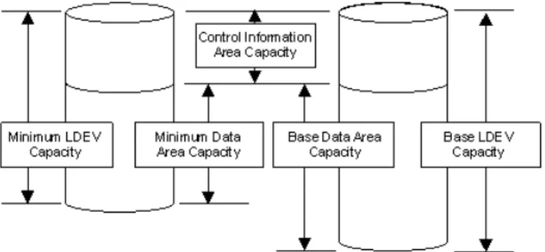
An external volume's capacity is carved into LDEVs when mapped to the local system as an internal volume. This topic provides information and instructions for calculating the capacity that the internal volume will have.
Note the following regarding internal/external volume capacity:
• The LDEV size in the internal volume varies according to the external system’s emulation type. • An external volume whose capacity is less than the minimum LDEV capacity cannot be used. • An external volume can be used whose capacity is less than the base LDEV capacity for the
emulation type; this causes a custom-sized volume (CV) to be automatically created in the local system during mapping.
• A custom volume in the local system has a minimum capacity, called minimum LDEV capacity. • Base LDEV capacity must equal or be greater than the minimum LDEV capacity.
Figure 1 Idea of LDEV capacity
• An external volume whose capacity is more than the base LDEV capacity for the emulation type results in multiple LDEVs created when the volume is mapped. These LDEVs will have the base LDEV capacity.
• When using VLL, a maximum 2,048 CVs can be created.
(VLL is not supported for the OPEN-L emulation type.)
• For emulation types other than OPEN-V, usable capacity in the internal volume is the capacity of the external volume minus control information area capacity.
• Data above the maximum capacity cannot be accessed.
LDEV capacities per emulation type
The following table shows LDEV capacities for each emulation type in units of blocks and cylinders. Control Information Area Capacity
Base Data Area Capacity Minimum Data Area Capacity
Emulation Type Cylinders Blocks Cylinders Blocks Cylinders Blocks Mainframe 7 10,080 3,339 4,808,160 50 72,000 3380-3 7 10,080 3,339 4,808,160 50 72,000 3380-3A 7 10,080 3,339 4,808,160 50 72,000 3380-3B 7 10,080 3,339 4,808,160 50 72,000 3380-3C 6 10,440 3,339 5,809,860 50 87,000 3390-3 6 10,440 3,339 5,809,860 50 87,000 3390-3A 6 10,440 3,339 5,809,860 50 87,000 3390-3B 6 10,440 3,339 5,809,860 50 87,000 3390-3C 6 10,440 3,339 5,809,860 50 87,000 3390-3R 25 43,500 10,017 17,429,580 50 87,000 3390-9 25 43,500 10,017 17,429,580 50 87,000 3390-9A 25 43,500 10,017 17,429,580 50 87,000 3390-9B 25 43,500 10,017 17,429,580 50 87,000 3390-9C
Control Information Area Capacity
Base Data Area Capacity Minimum Data Area Capacity
Emulation Type Cylinders Blocks Cylinders Blocks Cylinders Blocks 23 40,020 32,760 57,002,400 50 87,000 3390-L 23 40,020 32,760 57,002,400 50 87,000 3390-LA 23 40,020 32,760 57,002,400 50 87,000 3390-LB 23 40,020 32,760 57,002,400 50 87,000 3390-LC 53 92,220 65,520 114,004,800 50 87,000 3390-M 53 92,220 65,520 114,004,800 50 87,000 3390-MA 53 92,220 65,520 114,004,800 50 87,000 3390-MB 53 92,220 65,520 114,004,800 50 87,000 3390-MC 7 12,180 262,668 457,042,320 1,113 1,936,620 3390-A -1,117,760 1,944,902,400 50 87,000 3390-V OPEN -11,520 -4,806,720 -72,000 OPEN-3 -38,880 -14,351,040 -72,000 OPEN-8 -38,880 -14,423,040 -72,000 OPEN-9 -27,360 -28,452,960 -72,000 OPEN-E -10,080 -71,192,160 -71,192,160 OPEN-L -8,589,934,592 -96,000 OPEN-V
• For mainframe emulation types, LDEV capacity is an integer when converted to cylinders. • For 3380 mainframe volumes, 1 cylinder = 1,440 blocks
• For 3390 mainframe volumes, 1 cylinder = 1,740 blocks • 3390-A requires a control information area every 1,113 cylinders.
• For OPEN-L, CVs cannot be created. Therefore, the base data area capacity and minimum data area capacity are the same. • For OPEN-V:
- The maximum capacity of LDEVs is listed as the base data area capacity.
- The capacity of the external volume is equal to the capacity of the internal volume, when 4 TB or less. This is because there is no control information area capacity.
• For OPEN emulation types other than OPEN-V, LDEV capacity is divisible by 1,440 blocks.
Example: Determining capacity for OPEN-3 volume
The following figure illustrates capacity for an external volume with OPEN-3 emulation type. The capacity is 1,610,612,640 blocks. Using the data for OPEN-3 inLDEV capacities per emulation type (page 17), 334 LDEVS can be created from the base LDEV capacity of 4,818,240 blocks (Base Data Area plus Control Information Area).
This results in 1,320,480 blocks of the mapped external volume becoming free space. LDEVs can be created in free space using VLL.
Adjusting volume capacities for pairs
Mapped external volumes can be used for replication. All HP P9500 replication software requires a pair’s secondary volume (S-VOL) to have the same capacity as the primary volume (P-VOL). If you need to adjust the capacity of the HP P9500 volume or the external volume before creating the pair, proceed as shown in the following subtopics.
Decreasing the size of the HP P9500 S-VOL
When the HP P9500 volume S-VOL is larger than the mapped external volume P-VOL, adjust the HP P9500 volume’s capacity as follows:
1. Map the external volume with emulation type OPEN-V. 2. Make sure the HP P9500 volume’s emulation type is OPEN-V.
3. Decrease the size of the HP P9500 S-VOL by creating a custom volume (CV) using Virtual LVI/Virtual LUN, as shown in the following figure.
Base the CV capacity on Blocks, which displays in theCapacitycolumn on theLDEV Information dialog box in Remote Web Console. See the HP XP P9000 Provisioning for Open Systems
User Guide and the HP XP P9000 Provisioning for Mainframe Systems User Guide for
instructions on creating CVs. 4. Create the pair.
Decreasing the size of the external volume S-VOL
When the mapped external volume S-VOL is larger than the HP P9500 P-VOL, adjust the external volume’s capacity as follows:
1. Map the external volume with the same emulation type as the HP P9500 primary volume. 2. After mapping, check the new internal volume’s capacity. If it is larger than the HP P9500
P-VOL, decrease the size by creating a CV that is the same size as the HP P9500 P-VOL using Virtual LVI/Virtual LUN (see the following figure).
3. Create the pair.
Planning external paths and path groups
The external path is the physical link from the local storage system port to the external storage system port. You prepare the ports on the local and external systems and then set up the external path prior to mapping your external volumes.
To prepare and set up ports, see the following sections: • “Setting up ports on the local system” (page 29)
• “Setting up ports on the external system” (page 30)
External paths
A path consists of cables and possibly switches. You configure your path according to bandwidth considerations, which include distance, speed, and performance requirements.
Because workload can spike and cable or switch failures can occur, HP strongly recommends that you set up redundant external paths. A maximum of eight paths can be used per mapped external volume. Multiple paths—redundancy—allows you to perform I/O operations with external volumes regardless of workload and/or path failure.
With multiple paths, the external storage system determines how they are used: some systems use one primary path with alternates available as backups (Single path mode); other systems allow all paths to be used at the same time, distributing I/O among them (Multi path mode). The path storage system’s mode cannot be changed. With both modes, you place the paths in path groups and prioritize each path.
Single path mode
For Single path mode, the external path with the highest priority (primary path) is used to execute I/O to the external volume. If the primary path cannot be used, it is switched to an alternative path, after a 3-minute period.
NOTE: The 3-minute interval (the default) is configurable and may not always be 3 minutes. The following figure illustrates how failure is handled with redundant paths in Single path mode.
When you restore a path with higher priority than the currently-used path, I/O is switched to the restored path.
Multi path mode
For Multi path mode, all paths are used for I/O to the external volume. This distributes workload in a round-robin process.
The following figure illustrates how failure is handled with redundant paths in Multi mode.
NOTE: When you restore a path, use of the restored path is resumed.
Supported external systems’ path mode for external volumes
“Single” or “Multi” path mode displays in Remote Web Console for external volumes on theExternal Path Groupwindow. Path modes are based on the external storage system and cannot be changed. In APLB mode, all paths that are defined are used. I/O operation for external volumes is performed through load balancing with the use of several paths (round-robin control). External paths connected to ports in Passive status are not used.
Load Balance Mode
When the path mode of an external volume is Multi or APLB, you can select an I/O control system for the external storage system.
• Normal Round-robin: Normal multi-path I/O control system. This distributes I/O to several paths on which I/O operation is enabled for the external storage system. This mode is applied to external volumes mapped before 70-04-XX-XX/XX. Specify this if Extended Round-robin may lower I/O performance. This mode is recommended when the number of sequential I/O operations is small.
• Extended Round-robin: Extended multi-path I/O control system. I/O is distributed to several paths on which I/O operation is enabled for the external storage system. For sequential I/O, the external volume is divided into sections at regular intervals. In this case, the same path is used for I/O within the same section which reduces the frequency of I/O distribution. Read speed can be improved by using the cache function of the external storage system for sequential
I/O operations. This mode is recommended when the number of sequential I/O operations is large.
• Disable: I/O operation is performed with only one path that is normal and has the highest priority. The same operation applies as that for Single path mode. When Disable is set for Load Balance Mode, load distribution is not performed. This mode is not recommended. If your system is not shown below, refer tohttp://www.hp.com/storage/spock.
CAUTION: Depending on the external storage type and system configuration, performance may not be improved whenExtended Round-robinis set. In that case,Normal Round-robin is
recommended.
External path configurations — direct and switch
This topic provides recommendations for setting up direct and switch external path configurations.
Direct connection
The following figure shows redundant paths in a direct connection configuration. External storage system ports, "WWN A" and "WWN B", are connected to the local system ports, "CL1-A" and "CL2-A" (which are specified as external ports). For greater redundancy, Path 2, the alternate path, uses ports of a different cluster in both the local and external storage systems.
Switch connection
The following figure shows redundant paths with switches. Ports in the local system are connected to ports in the external system through the switch. The paths use ports of different clusters for increased redundancy.
Default mapping settings
Mapped volumes have default values that you can use or change before (or after) mapping. SeeEditing external volume policies (settings) (page 36) to review the settings and edit them if desired.
3 HP P9500 software supported for external volumes
You will use HP P9500 software products and functionality to manage and manipulate data in your mapped volumes: for example, Virtual LVI/Virtual LUN, Continuous Access Synchronous, LUN Manager, and so on.
This topic provides requirements and restrictions for the HP software supported with external volumes.
Cache Residency
Review the following when using external volumes with Cache Residency:
• If you set bind mode, a cache of twice as much capacity as the user data area of the mapped volume is required for the Cache Residency operation.
• Bind mode cannot be specified for an external volume if theCache Modeis set toDisableYou can specify theCache Modesetting before, during, or after mapping. SeeEditing external volume policies (settings) (page 36)for more information.
Snapshot
Mapped volumes can be used in pairs for Snapshot, with the following restrictions: • Both internal and external volumes cannot be used together in the same pool. • All external volumes in a pool must use the sameCache Modesetting.
After mapping and formatting an external volume, it is ready to use as a pair volume. The following figure shows an example of an external volume used as a Pool-Vol.
NOTE: All volumes in an external snapshot pool come from the same external storage array.
Thin Provisioning,Dynamic Provisioning for Mainframe, Smart Tiers, and
Smart Tiers Z, and Fast Snap
Mapped external volumes can be used as pool volumes for Thin Provisioning, Dynamic Provisioning for Mainframe, Smart Tiers, and Smart Tiers Z and Fast Snap.
• A mapped volume that is used as a pool volume must use OPEN-V emulation for open systems and 3390-V emulation for mainframe systems.
• All external volumes in the same pool must use the sameCache Modesetting. For more information about this setting, seeCache use and external storage performance (page 14). • With Smart Tiers, theCache Modesetting must beEnabled.
Local replication software
Mapped volumes can be used in pairs for Business Copy and Business Copy Z.
After mapping and formatting an external volume, it is ready to use as a pair volume. The following figure shows an example of an external volume used as an S-VOL (R-VOL in an BC Z pair).
LUN Manager and Configuration File Loader
Use LUN Manager to set the LU path for the mapped volume with OPEN systems emulation types. Some LUN Manager operations can be performed using spreadsheets and the Configuration File Loader function. When using external volumes, you can use Configuration File Loader for the following operations:
• Set the LU path definition for an external volume (add, delete, or change LU paths). • Set an external volume as a command device (add or delete the setting).
• Setting the channel adapter (CHA) mode, host group, and WWN for the external port is not supported. When an external volume is mapped through an external port, the port setting operation of the topology is not available.
LUN Expansion
External volumes can be used in a LUSE volume with the following restrictions:
• An internal volume in the local storage system and a mapped external volume cannot be combined to form a LUSE volume.
• Only LDEVs from the same external storage system can be used in a LUSE volume. Do not combine LDEVs of multiple external storage systems to create a LUSE volume, otherwise the following occurs:
◦
When one external volumes is lower performing than others, it affects the performance of the LUSE volume.◦
If an external volume that is part of a LUSE volume is blocked, the data reliability of the LUSE volume deteriorates because the LUSE volume has both accessible areas and inaccessible areas from a host.◦
If an external volume in a LUSE volume is disconnected or reconnected, all external volumes in the LUSE volume must be disconnected or reconnected at the same time. • All external volumes in a LUSE volume must use the sameCache Modesetting. For moreinformation about this setting, see“Cache use and external storage performance” (page 14).
Performance Monitor and Auto LUN V2
Performance Monitor can be used to display monitoring information for mapped external volumes. Mapped volumes can also be used for Auto LUN. The following figure shows an example of an external volume used as the source volume in a Auto LUN operation. Existing data in the external volume is migrated manually to the local system’s native internal volume.
Procedure 1 To use an external volume for volume migration
1. Map the external volume. If using the external volume as a source volume, setEmulation Type toOPEN-V. This is required to access existing data in an external volume from the local system (for volume migration as well as replication).
2. Ensure that both volumes have the same capacity. Adjust the capacity as needed using the LUSE and the Virtual LVI/Virtual LUN functions.
3. Set the source and target volumes. 4. Migrate the data using Auto LUN.
Remote replication software
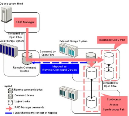
Mapped external volumes can be used with the following remote replication software:
• Continuous Access Synchronous
• Continuous Access Synchronous Z
• Continuous Access Journal • Continuous Access Journal Z
After mapping and formatting an external volume, it is ready to use as a pair volume. The following figures show examples of an external volume used as an S-VOL (T-VOL in a Cnt Ac-S Z pair). Figure 2 Cnt Ac-J and Cnt Ac-J Z example using a mapped external volume
Figure 3 Cnt Ac-S and Cnt Ac-S Z example using a mapped external volume
SNMP Agent
Information about both the mapped external volume and the External port can be displayed by SNMP Agent.
Customized Volume
For mainframe external volumes, use the Virtual LVI function to format or to perform the Write to Control Blocks operation immediately after mapping. See the HP XP P9000 Provisioning for
Mainframe Systems User Guide for information.
If you create LDEVs from an external volume using the Virtual LVI or Virtual LUN function, theCache Modesetting of the created LDEVs is the same as the mapped external volume.
4 Setting up external volumes
You set up ports and external paths, map the external volume, then begin using it with native storage on the HP P9500. This topic provides setup procedures and information.
Setup workflow
When you begin setting up External Storage, all planning tasks and considerations should be completed. Consult the topics in“Planning workflow” (page 11)to review.
Set up external volumes as follows:
1. Set up ports on the local and external storage systems. See the following: • “Setting up ports on the local system” (page 29)
• “Setting up ports on the external system” (page 30)
2. To edit certain mapping settings prior to the mapping operation, seeEditing external volume policies (settings) (page 36). Otherwise, you can make changes during the operation or accept the default settings.
3. Map the external volume to the HP P9500. See“Mapping an external volume” (page 30).
4. When the external volume is successfully mapped, perform the one of the following based on the volume’s emulation type:
• For mainframe emulations, format the volume or perform the Write to Control Blocks operation using Virtual LVI. See the HP XP P9000 Provisioning for Mainframe Systems
User Guide.
• For OPEN-system emulation, define LU paths to a host using LUN Manager. See the HP
XP P9000 Provisioning for Open Systems User Guide.
See Also:
“Recognizing local system from the external system” (page 35).
Setting up ports on the local system
A port on the HP P9500 must connect with the port on the external system via the external path. The HP P9500 port must be specified as an “External” port. This topic provides instructions for changing the Fibre Channel port attribute to “External”.
Prerequisites
• Before changing the port’s attribute, release LU paths that may be assigned to the port. • Ports with RCU target and Initiator attributes can be changed to External, but ensure that they
are no longer used for remote copy.
• For more information about setting up the external path, see“Planning external paths and path groups ” (page 20).
Procedure 2 To set a port attribute to external
1. In the Remote Web ConsoleStorage Systemstree, click thePorts/Host Groups link. 2. In thePorts/Host Groupswindow, select thePorts tab.
3. On thePorts tab, select the desired port row.
4. On the menu bar, clickActions,Ports/Host Groups, and thenEdit Ports. 5. On theEdit Portswindow, selectExternalin the Port Attributebox.
6. For help with other settings, see the HP P9000 Provisioning for Mainframe Systems User Guide or HP P9000 Provisioning for Open Systems User Guide.
7. When ready, clickFinish.
8. In theConfirmwindow, check all settings, accept or enter a new task name, and then click Apply.
9. When ready, clickFinish.
10. In theConfirmwindow, check all settings, accept or enter a new task name, and then click Apply.
Setting up ports on the external system
Make sure the external system ports you use can handle the read and write workload planned for the external volumes. See the discussion in“External paths” (page 20) for more information. The following are general steps for setting up external-system ports. Refer to the documentation for the external system for full information.
1. Set the topology information according to the configuration of the connection (fabric or loop). 2. Set the data transfer speed according to the connection configuration.
3. Set parameters for the ports on the external system as required for connecting with the HP P9500. For your specific external system, seeSupported external storage systems (page 62). If you do not find your external system in the section, seehttp://www.hp.com/storage/spock
to make sure your system is supported, then refer to the documentation for the system’s ports. 4. Define LUNs and present them on the port on the external system.
Mapping an external volume
After setting the attribute of the port used for External Storage to the external port, you can map the external volume as an internal volume.
Prerequisite information
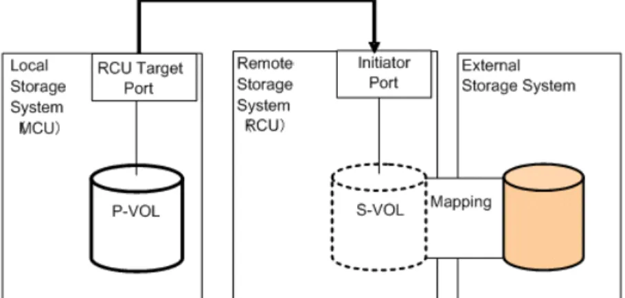
• Attributes set for the external volume before mapping, such as port security, LUN security, Volume Retention attributes, and so on are discarded when the external volume is mapped. If the original attributes are required, reset them in the local storage system after mapping. • When the external volume is a command device, it is mapped as a remote command device.
For important information about mapping command devices, see“Remote command devices” (page 76).
• Before you map the external volume, check whether any application is using the volume. If so, stop the application before mapping.
For example, if mapping a command device, make sure RAID Manager commands are not being executed during the mapping operation.
NOTE: When you create an LDEV at the same time that you map an external volume, you cannot select the following LDEV numbers:
• Numbers already in use.
• Numbers already assigned to another emulation group (grouped every 32 LDEV numbers). • Numbers not assigned to the user.
For emulation groups, see P9000 Provisioning for Open Systems User Guide or P9000 Provisioning
for Mainframe Systems User Guide. To determine whether the LDEV number can be assigned, click
theView LDEV IDsbutton in theAdd External Volumeswindow when you map the external volume. Procedure 3 To map an external volume
1. In Remote Web Console, selectAdd External Volumesfrom the General Tasksmenu. 2. In theAdd External Volumeswindow, add the external volume by clicking eitherBy New
• To add the external volumeBy New External Path Group: a. ClickCreate External Path Group.
b. In theCreate External Path Groupwindow, enter the following:
—Initial External Path Group ID. The storage system searches IDs from the initial ID you specify in ascending order and allocates an ID that can be used. The range can be from 0 to 63,231. 0 is the default.
—External Paths. If you do not see the port or WWN you want in theAvailable External Pathbox, clickDiscover External Target Ports. In the new window, select the desired ports and click Add, then clickOK.
—External Storage System. If the external system is not selected, scroll down the list and select it.
—Available External Path. Select the desired port IDs and clickAdd, then clickOK. c. Set the priority for a path by selecting it and clickingRaise Priority orLower Priority. d. ClickOK.
• To add the external volumeBy Existing External Path Group: a. ClickBy Existing External Path.
b. If you have not identified the external storage system that you want to connect the external path to, click the storage system button and select the system.
c. In theAvailable External Path Groupslist, select the desired path group. Path groups consist of the external paths previously set up and prioritized.
d. ClickNext.
3. In theAdd External Volumeswindow’sDiscovered External Volumesbox, select the desired external volumes.
4. InInitial Parity Group ID, enter an external volume group number and sequential number. A group allows you to place similar external volumes in a group; for example, volumes used for a copy function.
The range is from 1 - 1 to 16384 - 4096.
5. InAllow Simultaneous Creation of LDEVs, selectYesto allow the system to automatically create LDEVs in the external volume, otherwise selectNo.
If the external volume is a command device, selectYesin both Allow Simultaneous Creation of LDEVsandUse External Storage System Configuration.
6. InUse External Storage System Configuration, selectYesto use the external storage system’s configuration when the local system create LDEVs (ifAllow Simultaneous Creation of LDEVsis alsoYes). Otherwise, selectNo.
• If you selectYes, an LDEV whose emulation type is OPEN-V and has the same capacity as the external volume is created (maximum capacity of an OPEN-V LDEV is 4 TB). • If you selectNo, the Optionslist expands. You must select anEmulation Typewhen you
selectNo.
If the external volume is a command device, selectYesin both Allow Simultaneous Creation of LDEVsandUse External Storage System Configuration.
7. InLDEV Name, enter the prefix character and the initial number.
The entire value can be a maximum of 32 characters including the initial number (numerical value of 9 digits or less), or blank. Blank is displayed by default. Note the following numbering rule:
• 1:total 9 numbers (1,2,3,…9)
• 08:total 92 numbers (08,09,10,…99)
• 23:total 77 numbers (23,24,25,…99)
• 098:total 902 numbers (098,099,100…999)
8. ClickOptions(if not already expanded). If you have previously edited mapping settings (policies), you may not want to change the options. However, review the following steps—since some fields inOptionsare affected by preceding steps.
9. In the expandedOptionsbox, forInitial LDEV IDenter the initial LDEV ID for the external volume. The local storage system searches from this number in ascending order and allocates the next available ID. You can review used, available, and disabled LDEVS by clickingView LDEV IDs.
• ForLDKC, enter 00.
• ForCU, enter the CU number, which can from 00 to FE. 00 is the default. • ForDEV, enter the LDEV ID, which can be from 00 to FF. 00 is the default.
• ForInterval, enter an interval between LDEV IDs, which can be from 0 to 255. 0 is the default.
10. InInitial SSID, enter the SSID, which can be from 0004 to FFFE. 0004 is the default. You can review the current SSIDs by clickingView SSIDs.
11. InBase Emulation Type, select the emulation type of the external volume.
If you selectedYesin Allow Simultaneous Creation of LDEVsandNoin Use External Storage System Configuration, you must select an emulation type. If you selectedYesin both fields, Base Emulation Typeis greyed out, and OPEN-V is automatically set.
12. InNumber of LDEVs per External Volume, enter the number of LDEVs to be created when the volume is mapped. This field is greyed out if you selectedYesinAllow Simultaneous Creation
of LDEVsandUse External Storage System Configuration, and1displays (since OPEN-V is the emulation type). SeeCapacity requirements for volumes (page 16)for more information. 13. InCache Partition, select the CLPR for accessing the mapped external volume.
NOTE: For more information about the Cache Partition,Cache Mode, andInflow Control settings, see Editing external volume policies (settings) (page 36).
14. InCache Mode, clickEnableto propagate write data asynchronously from cache to the external storage system. ClickDisable to propagate data synchronously.
• If you specifyDisable, the Cache Residency bind mode cannot be set.
• When the external volume is a command device,Cache Modefor the remote command device is automatically set toDisable regardless of your setting.
• Data that is not written by the host (for example, data written by pair operation) is asynchronously destaged to the external storage system regardless of theCache Mode setting.
15. InInflow Control, clickEnableto limit or prevent write data from being written to cache memory when the write operation to the external volume cannot be performed. ClickDisableto allow write data to be written to cache.
16. InProcessor Blade, select the processor blade for the external volume. Processor blade assignment should evenly distribute work across the available processors.
The range is from MPB0 to MPB7. The value depends on the configuration of the device. SelectAuto(the default) to cause a processor blade to be automatically assigned by the system. IfAuto cannot be selected, the processor blade with the lowest number is selected by default. 17. ClickAdd.
18. If you need to change the added volume’s settings, in theSelected External Volumeslist click the volume, click Change Settings, make necessary changes, and clickOK.
19. ClickOK.
To to add LUN paths, click Nextin theAdd External Volumeswindow. See the HP XP P9000
Provisioning for Open Systems User Guide for information.
20. ClickFinishwhen ready.
21. In theConfirmwindow, check all settings, accept or enter a new task name, and then click Apply.
Preparing mapped volumes for use
After your external volume is mapped to the local storage system, proceed as follows: Procedure 4 To prepare mapped volumes for use
1. Based on emulation type, perform one of the following:
• For mainframe emulation, the status of the mapped volume becomesBlockade after mapping. Format the volume using Virtual LVI to change to a normal status.
For zero-formatted external volumes, use Virtual LVI to perform theWrite to Control Blocks operation to restore the volume. Even if you formatted the volume from the external storage side after recovering the mapped volume, you must perform theWrite to Control Blocks operation of the VLL feature after the formatting. For instructions, see the HP P9000
Provisioning for Mainframe Systems User Guide.
• For open-system emulation, the status of the mapped volume automatically becomes Normal. If you need to initialize the data area of the mapped volume, format the volume using Virtual LUN.
2. For both emulation types, set an LU path from a Target port to the internal volume, as shown in the following figure.
The LU path enables host I/O to the mapped volume.
Using mapped volumes
When external volumes are mapped and ready for use, you can perform the operations supported by External Storage. Review supported software products and operations in“HP P9500 software supported for external volumes” (page 25).
NOTE: A mapped external volume can be accessed only from the local system. Do not access the volume from a host connected to the external storage system.
Also, do not use external storage system functions to access the mapped external volume, including copy functions.
Recognizing local system from the external system
Though the local and external systems are connected, the external system may not recognize the local system. If desired, you can try to make this happen by performing the Discover External Target Ports operation. See“Adding an external path to an existing path group ” (page 40)for instructions. If the path does not become mapped after 15 minutes, though, the external system might not be able to recognize the local system.
5 Monitoring and maintenance
This topic provides monitoring, editing, and maintenance instructions for external volumes, paths, and systems.
Monitoring external volumes and paths
You can view system details about mapped external volumes, the ports used, and the external paths.
Procedure 5 To view mapped external volumes and paths
1. In Remote Web Console, clickExternal Storagesin the Storage Systemstree. 2. Select an external storage system.
3. Select a path group.
4. Select theMapped Volumestab.
5. Select an external volume row. ClickExternal LUN Propertiesat the bottom of the window.
Editing external volume policies (settings)
When you map new external volumes, preset mapping policies are used. You can change default mapping values without affecting settings in previously mapped volumes.
To reset the values for previously mapped volumes, go to theEdit External Volumes window and change settings volume by volume.
The settings and their functions are described in the following bullets. To skip to the procedure, seeEditing mapping policies (page 37).
• Base Emulation Type
Specify OPEN-V to use existing data in the external volume from HP P9500.
◦
◦
If you use an emulation type other than OPEN-V, the volume requires a specific area for management data. This results in a volume capacity after mapping that is less than the actual external volume capacity.SeeCapacity requirements for volumes (page 16) for more information about capacity and calculating the capacity of your external volume.
• Cache Mode. I/O to and from the local storage system always uses cache. Write operations are always backed up in duplex cache. TheCache Modesetting specifies whether write data from the host is written to the external volume asynchronously (Enable) or synchronously (Disable).
◦
If Enableis specified: After receiving the data into the local system’s cache memory, the system signals the host that the I/O operation has completed and then asynchronously destages the data to the external volume.◦
WhenDisableis specified (the default): After synchronously writing the data to the external volume, the local system signals the host that an I/O operation has completed.For further discussion, see“Cache use and external storage performance” (page 14).
• Cache Partition. Cache memory can be partitioned using Cache Partition to configure a cache logical partition (CLPR) for the mapped volumes. Cache logical partitions are often used to limit cache-use by accessing slower external storage volumes.
HP strongly recommends that you place external storage array groups in a CLPR other than CLPR0. See the HP XP P9000 Cache Partition User Guide for detailed information on CLPR.
• Inflow Control. When the write operation to the external volume cannot be completed,Inflow Controlspecifies whether the write operation to cache memory is limited (Enable) or continued (Disable).
◦
IfEnableis specified, the write operation to cache is limited and I/O from the host is not accepted. Limiting the write operation prevents the accumulation of data that cannot destage to cache memory.◦
WhenDisable(the default) is specified, I/O from the host during the retry operation is written to cache memory. When write operations to the external volume are again possible, data in cache memory is written to the external volume (all data is destaged).• Load Balance Mode. When the Path mode is Multi or APLB, selectNormal Round-robin, Extended Round-robin, orDisable as a Load Balance Mode for the external storage system. By default, Normal Round-robin is used. However, when the product name of the storage system is displayed as “generic”,Disable is used by default.
◦
Normal Round-robin: I/O is distributed to several paths on which I/O operation is enabled for the external storage system.◦
Extended Round-robin: I/O is distributed to several paths on which I/O operation is enabled for the external storage system. For sequential I/O, the external volume is divided into sections at regular intervals. In this case, the same path is used for I/O within the same section which reduces the frequency of I/O distribution.◦
Disable: As in Single mode, I/O operation is performed using the path that has the highest priority of all paths on which I/O operation is enabled for the external storage system.Editing mapping policies
1. In Remote Web Console, clickExternal Storagesin the Storage Systemstree. 2. In theExternal Storageswindow, select the row for an external storage system. 3. At the bottom of the window, clickMore Actions > Edit Policies.
4. In theEdit Policieswindow, use the information in the previous sections to enter new settings.
NOTE: You can also editCache ModeandInflow Controlfor individual external volumes. In Remote Web Console, select an external volume in theMapped Volumestab. Then click Edit External Volumes.
5. ClickApply.
Changing external volume processor blade
Procedure 6 To change the processor blade
1. In Remote Web Console, clickExternal Storagesin the Storage Systemstree. 2. In theExternal Storageswindow, select the desired external storage system. 3. In the window for the selected external storage system, select a path group.
4. In the window for the selected path group, select the external volume whose processor blade you want to change.
5. At the bottom of the window, clickMore Actions > Assign MP Blade. 6. In theAssign Processor Bladewindow, select the desired processor blade.
The current setting for the external volume displays, unless you have selected multiple external volumes with different values. Then the field is blank.
The choices you see are dependent on the configuration of the device. They range fromMPB0 toMPB7.
NOTE: Processor blade assignment should be set to evenly distribute work across all the available processors.
SelectingAuto allows the system to assign the blade. 7. ClickFinish.
8. In theConfirmwindow, check settings, accept or enter a new task name, and then clickApply.
Changing I/O system for external storage systems
With Load Balance Mode settings, you can change the I/O system for external storage systems for each of the external volumes.
This section describes operations to change the Load Balance Mode of external volumes in the Edit External Volumes window. For more information, see“Load Balance Mode” (page 22). NOTE: To change the Load Balance Mode, the path mode of the external volume must be either Multi or APLB.
To change the Load Balance Mode for each external volume: 1. ClickExternal Storagesin the Storage Systems.