LatticeMico32 Software
Developer User Guide
Copyright
Copyright © 2012 Lattice Semiconductor Corporation.
This document may not, in whole or part, be copied, photocopied, reproduced, translated, or reduced to any electronic medium or machine-readable form without prior written consent from Lattice Semiconductor Corporation.
Trademarks
Lattice Semiconductor Corporation, L Lattice Semiconductor Corporation (logo), L (stylized), L (design), Lattice (design), LSC, CleanClock, Custom Movile Device, DiePlus, E2CMOS, Extreme Performance, FlashBAK, FlexiClock, flexiFLASH, flexiMAC, flexiPCS, FreedomChip, GAL, GDX, Generic Array Logic, HDL Explorer, iCE Dice, iCE40, iCE65, iCEcable, iCEchip, iCEcube, iCEcube2, iCEman, iCEprog, iCEsab, iCEsocket, IPexpress, ISP, ispATE, ispClock, ispDOWNLOAD, ispGAL, ispGDS, ispGDX, ispGDX2, ispGDXV, ispGENERATOR, ispJTAG, ispLEVER, ispLeverCORE, ispLSI, ispMACH, ispPAC, ispTRACY, ispTURBO, ispVIRTUAL MACHINE, ispVM, ispXP, ispXPGA, ispXPLD, Lattice Diamond, LatticeCORE, LatticeEC, LatticeECP, LatticeECP-DSP, LatticeECP2, LatticeECP2M, LatticeECP3, LatticeECP4, LatticeMico, LatticeMico8, LatticeMico32, LatticeSC, LatticeSCM, LatticeXP, LatticeXP2, MACH, MachXO, MachXO2, MACO, mobileFPGA, ORCA, PAC, PAC-Designer, PAL, Performance Analyst, Platform Manager, ProcessorPM, PURESPEED, Reveal, SiliconBlue, Silicon Forest, Speedlocked, Speed Locking, SuperBIG, SuperCOOL, SuperFAST, SuperWIDE, sysCLOCK, sysCONFIG, sysDSP, sysHSI, sysI/O, sysMEM, The Simple Machine for Complex Design, TraceID, TransFR, UltraMOS, and specific product designations are either registered
trademarks or trademarks of Lattice Semiconductor Corporation or its subsidiaries in the United States and/or other countries. ISP, Bringing the Best Together, and More of the Best are service marks of Lattice Semiconductor Corporation.
Other product names used in this publication are for identification purposes only and may be trademarks of their respective companies.
Disclaimers
NO WARRANTIES: THE INFORMATION PROVIDED IN THIS DOCUMENT IS “AS IS” WITHOUT ANY EXPRESS OR IMPLIED WARRANTY OF ANY KIND INCLUDING WARRANTIES OF ACCURACY, COMPLETENESS, MERCHANTABILITY, NONINFRINGEMENT OF INTELLECTUAL PROPERTY, OR FITNESS FOR ANY PARTICULAR PURPOSE. IN NO EVENT WILL LATTICE SEMICONDUCTOR CORPORATION (LSC) OR ITS SUPPLIERS BE LIABLE FOR ANY DAMAGES WHATSOEVER (WHETHER DIRECT, INDIRECT, SPECIAL, INCIDENTAL, OR CONSEQUENTIAL, INCLUDING, WITHOUT LIMITATION, DAMAGES FOR LOSS OF PROFITS, BUSINESS INTERRUPTION, OR LOSS OF INFORMATION) ARISING OUT OF THE USE OF OR INABILITY TO USE THE INFORMATION PROVIDED IN THIS DOCUMENT, EVEN IF LSC HAS BEEN ADVISED OF THE POSSIBILITY OF SUCH DAMAGES. BECAUSE SOME JURISDICTIONS PROHIBIT THE EXCLUSION OR LIMITATION OF CERTAIN LIABILITY, SOME OF THE ABOVE LIMITATIONS MAY NOT APPLY TO YOU.
LSC may make changes to these materials, specifications, or information, or to the products described herein, at any time without notice. LSC makes no commitment to update this documentation. LSC reserves the right to discontinue any product or service without notice and assumes no obligation to correct any errors contained herein or to advise any user of this document of any correction if such be made. LSC recommends its customers obtain the latest version of the relevant information to establish, before ordering, that the information being relied upon is current.
Type Conventions Used in This Document
Convention Meaning or Use
Bold Items in the user interface that you select or click. Text that you type into the user interface.
<Italic> Variables in commands, code syntax, and path names. Ctrl+L Press the two keys at the same time.
Courier Code examples. Messages, reports, and prompts from the software.
... Omitted material in a line of code. .
. .
Omitted lines in code and report examples.
[ ] Optional items in syntax descriptions. In bus specifications, the brackets are required.
( ) Grouped items in syntax descriptions. { } Repeatable items in syntax descriptions.
Contents
Chapter 1 LatticeMico System Overview 1 LatticeMico System Design Flow 1
Device Support 3 Design Flow Steps 4
About LatticeMico System Software Projects 6 Project/Build Management 6
Application Debugging 6 Software Deployment 7 Related Documentation 7
Chapter 2 Using the LatticeMico System Software 9 LatticeMico System Software Overview 9
About the LatticeMico System Tools 9 LatticeMico System Requirements 10 Running LatticeMico System 10 LatticeMico System Perspectives 10 Using C/C++ SPE to Develop Your Software 15
Starting C/C++ SPE 15 Creating Software Projects 17 Basic Project Operations 20
Understanding the Build Process 24 Building Your Software Project 25 Setting Project Properties 26 Rebuilding Your Software Project 30 Performing Builds Automatically 30
Using LatticeMico System as a Stand-Alone Tool 31 Running the Debugger on Your Code 32
CONTENTS
Command-Line Managed Project Builds 43 Command-Line Unmanaged Project Builds 44 Chapter 3 LatticeMico Run-Time Environment 45
Build/Compilation Utilities 45 Run-Time Libraries 45
Newlib C and Math Libraries 46 Device Drivers and Services 52
Services Available at Run Time 53 Device Driver APIs 56
Basic Program Structure 57 Creating a Blank Project 58
Adding a Source File to the Project 59 Adding Source to the Source file 61 Building the Application 62
Boot Sequence and crt0ram.S 64 The int main(void) Function 73
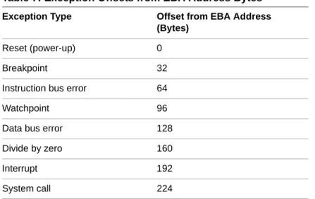
Context Save/Restore in Interrupt Exception 73 Boot Sequence 76
EBA and DEBA 77
Boot Code Sequence Flow 79 LatticeMico32 Microprocessor Usage 80
Data Types 80 Byte Order 80
Interrupt Management 81 Cache Management 88 Sleep (Busy) Functions 89
Microprocessor Control Register Access 90 Macros 90
Run-Time Services 91
Device Lookup Service 91
LatticeMico System Timer Services 95 LatticeMico File Service 98
CFI Flash Device Service 105 Chapter 4 Device Driver Framework 121
Overview 121
Supported Components 122
Modifying Existing Device Drivers 123
Overriding Default Driver Initialization Sequence 123 Overriding Default Driver Implementation 124 Enhancing CFI Flash Service 125
Making Devices Available to Lookup Service 130 File Operations 131
File Operations Functions 131
File Device and LatticeMico File Service 132 Maximum File Descriptors 136
Developing File Device Drivers 137
Implementing the Operation Functions 138 Registering the Driver as a File Device 139 File Device Function Handlers 142
CONTENTS
Chapter 5 Managed Build Process and Directory Structure 145 Creating Managed Build Applications 145
LatticeMico C/C++ Project Build Flow 146 The Build Process 147
Build Directory Structure 148
Platform Library-Generated Source Files 155 DDStructs.h File 157
DDStructs.c File 159 DDInit.c File 160 System_Conf.h File 161
Component Software Elements 168 Chapter 6 Advanced Programming Topics 175
Linker Script and Memory Sections 175 Software Deployment 178
Deployment Strategies 178
Deploying to On-Chip Memory 179
Deploying to Multiple On-Chip Memory 190 Deploying to a Flash Device 193
Deploying to SPI Flash Using Deployment Tool 199
Deploying Applications Across Different Memory Components 211 Device Drivers and Multitasking 244
Standard-Make Projects 244
Creating a LatticeMico Library Project 245
Creating a LatticeMico Standard-Make Project 250 Chapter 7 Software Development Utilities 281
Build Tools 281 lm32-elf-ar 281 lm32-elf-as 283 lm32-elf-gcc 285 lm32-elf-ld 287 lm32-elf-nm 292 lm32-elf-objcopy 293 lm32-elf-objdump 296 lm32-elf-size 298 Debug Tools 299
lm32-elf-gdb 299 Glossary 301 Index 307
Chapter 1
LatticeMico System Overview
This software developer’s guide describes the flow of tools involved in creating, debugging, and deploying the software application code for the LatticeMico32 embedded microprocessor. In addition, it familiarizes you with the LatticeMico run-time environment, the managed build environment, and its associated directory structure. “Device Driver Framework” on page 121 describes the device driver framework and the advanced issues related to developing custom device drivers. Some treatment is also given to a command-line approach in “Using the LatticeMico System Software” on page 9, with “Software Development Utilities” on page 281 containing tool syntax and options for usage.
This guide is targeted to software programmers who are interested in learning the fundamentals of programming the embedded soft-core microprocessor. For a list of related documents on the LatticeMico32 microprocessor, refer to “Related Documentation” on page 7.
LatticeMico System Design Flow
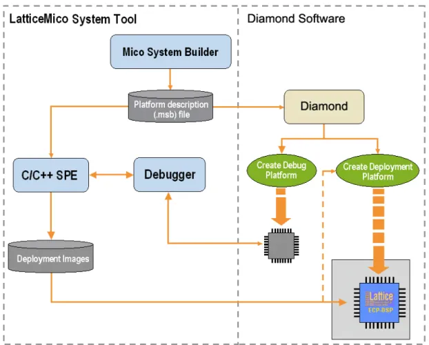
This section lists the major steps involved in designing a LatticeMico32 embedded microprocessor. In addition to running the FPGA flow in Lattice Diamond, you will use the LatticeMico System software to build both
hardware and software features of your embedded soft-core microprocessor. The LatticeMico System software is composed of three bundled applications: Mico System Builder (MSB)
LATTICEMICO SYSTEM OVERVIEW : LatticeMico System Design Flow
software. Perspectives are a prearranged and predefined set of user
functions that can be accessed within the software user interface. You toggle different perspectives on and off by clicking on perspective tabs. Perspectives are described in more detail in “LatticeMico System Perspectives” on
page 10.
MSB is used by hardware designers to create the microprocessor platform for both hardware and software development. A platform generically refers to the hardware microprocessor configuration, the CPU, its peripherals, and how these components are interconnected. This functionality in the LatticeMico System software can be accessed by using the MSB perspective in the interface. The default MSB perspective is completely separate in terms of function from the other two perspectives. For complete information about using MSB, refer to the LatticeMico32 Hardware Developer User Guide. You can use the C/C++ Software Project Environment (SPE) to develop the software application code that drives the platform. The Debugger is used to analyze and correct your code. You can access these programs by enabling the C/C++ and Debug perspectives, respectively. However, these two perspectives overlap in terms of functionality. Many of the same functions and views available in the C/C++ perspective are also available in the Debug perspective because the functions are so intertwined.
LATTICEMICO SYSTEM OVERVIEW : LatticeMico System Design Flow
Figure 1 shows the interaction of the three LatticeMico System applications with Lattice Diamond in the microprocessor development design flow.
As noted earlier, you can learn more about perspectives in “LatticeMico System Perspectives” on page 10. In addition, the LatticeMico32 Tutorial
gives step-by-step instructions on creating a sample microprocessor platform, downloading hardware images to your device, creating your application code, and deploying your application code to on-chip or flash memory. It covers all relevant topics to enable you to run through a complete LatticeMico design flow. It is highly recommended that you start out with the tutorial.
Device Support
The Lattice FPGA devices that are currently supported in this design flow are the following:
LatticeECP
LATTICEMICO SYSTEM OVERVIEW : LatticeMico System Design Flow
LatticeECP2M LatticeECP3 LatticeXP LatticeXP2 LatticeSC LatticeSCM
Design Flow Steps
The major steps involved in designing a LatticeMico32 soft-core microprocessor are the following:
1. Create a project in Lattice Diaimond that targets the desired device family. 2. Use the Mico System Builder (MSB) in the LatticeMico System software to
create and develop a microprocessor platform. You access this in the MSB perspective. Creating a platform involves generating an .msb file, selecting component peripherals, and connecting them to the LatticeMico platform. For complete instructions, refer to the LatticeMico32 Hardware Developer User Guide.
3. In the MSB perspective, designate and develop drivers as necessary for available peripherals and add them to the platform you created.
4. In the MSB perspective, generate a platform build, which automatically creates a build structure with associated makefiles and an appropriate linker script. This process involves the device drivers and any other software components other than the user application.
5. In C/C++ SPE, use the C/C++ perspective to write the C/C++ user application software and build your application.
6. Using the Debugger in the LatticeMico System software, test your code on the target hardware, configure the target hardware, find issues with your code, and correct them. You access the Debugger in either the
C/C++ perspective or the Debug perspective.
7. In Diamond, download the executable code to on-board flash memory. You can deploy the application providing a boot loader that straps onto the application for loading the application from slow, non-volatile storage (flash memory device) to fast volatile storage (on-chip or off-chip RAM), without having to rebuild the application.
8. Repeat steps 3 through 7 for any new application development or modification to the platform in step 2.
LATTICEMICO SYSTEM OVERVIEW : LatticeMico System Design Flow
Figure 2 shows the LatticeMico System design flow. Figure 2: LatticeMico System Design Flow
LATTICEMICO SYSTEM OVERVIEW : About LatticeMico System Software Projects
About LatticeMico System Software Projects
The LatticeMico System project concept enables you to develop your
embedded microprocessor in an integrated environment that automates some of the tasks described in “LatticeMico System Design Flow” on page 1 and makes other tasks more manageable for you.
A LatticeMico System project is a managed project, which means that the software generates a set of makefiles and build management utilities for you to ensure that your software project is built and generated properly, making it unnecessary for you to modify any files to perform this task.
The software system consists of three major functional parts: Project/build management
Application debugging Software deployment
Project/Build Management
The project/build management function of the software does the following: Automatically selects Lattice Semiconductor-provided, platform-specific
drivers (operating system and other selectable software components) based on the .msb file that defines your platform, user selections, or both. Automatically creates the appropriate makefiles for building the
application, as well as included drivers and software components, without user intervention.
Provides default project settings, as well as build configuration, to enable you to successfully generate basic platforms and requirements.
Enables easy manipulation of linker section location for platforms containing a multitude of memory regions through an intuitive user interface.
See “Managed Build Process and Directory Structure” on page 145 for details on the managed build process.
Application Debugging
The application debugging function of the software does the following: Provides a default debug session configuration that builds the application
in a way that allows you to run and diagnose issues within your application code.
Provides an intuitive source-level debugging environment that gives you a comprehensive look at the application/CPU during a debug session. See “Running the Debugger on Your Code” on page 32 and all relevant subsections for information on application debugging.
LATTICEMICO SYSTEM OVERVIEW : Related Documentation
Software Deployment
The software application can be deployed in three different ways: To boot from a flash device
To boot from an on-chip memory peripheral component To boot from multi on-chip memory
See “Software Deployment” on page 178 and relevant procedures in “Using the LatticeMico System Software” on page 9 for deploying your software.
Related Documentation
You can access the LatticeMico System online Help and manuals by choosing Help > Help Contents in the LatticeMico System interface. These manuals include the following:
LatticeMico32 Processor Reference Manual, which contains information on the architecture of the LatticeMico32 microprocessor chip, including configuration options, pipeline architecture, register architecture, debug architecture, and details about the instruction set.
LatticeMico32 Hardware Developer User Guide,which provides instructions for using the MSB perspective to develop and configure a hardware platform using the LatticeMico32 microprocessor, peripherals, and IP.
LatticeMico32/DSP Development Board User Guide, which describes the
features and functionality of the LatticeMico32/DSP development board. This board is designed as a hardware platform for design and
development with the LatticeMico32 microprocessor, as well as for the LatticeMico8 microcontroller, and for various DSP functions.
Eclipse C/C++ Development Toolkit User Guide, which is an online manual from Eclipse that gives instructions for using the C/C++ Development Toolkit (CDT) in the Eclipse Workbench.
LatticeMico Asynchronous SRAM Controller, which describes the features and functionality of the LatticeMico asynchronous SRAM controller LatticeMico DMA Controller, which describes the features and
functionality of the LatticeMico DMA controller
LatticeMico On-Chip Memory Controller, which which describes the features and functionality of the LatticeMico on-chip memory controller LatticeMico Parallel Flash Controller, which describes the features and
functionality of the LatticeMico parallel flash controller
LatticeMico GPIO, which describes the features and functionality of the LatticeMico GPIO
LATTICEMICO SYSTEM OVERVIEW : Related Documentation
LatticeMico SDR SDRAM Controlller, which describes the features and functionality of the LatticeMico SDR SDRAM controller
LatticeMico SPI, which describes the features and functionality of the LatticeMico serial peripheral interface (SPI)
LatticeMico SPI Flash, which describes the features and functionality of the LatticeMico serial peripheral interface (SPI) flash memory controller LatticeMico Timer, which describes the features and functionality of the
LatticeMico timer
LatticeMico UART, which describes the features and functionality of the LatticeMico universal asynchronous receiver-transmitter (UART) Lattice Diamond <release_number> Installation Notice, which explains
how to install the LatticeMico System software for the current release LatticeECP/EC FPGA Family Handbook, which is a collection of the data
sheets and application notes on LatticeEC and LatticeECP devices
LatticeECP/EC Family Data Sheet
LatticeECP2 FPGA Family Handbook, which is a collection of the data sheets and application notes on LatticeECP2 devices
LatticeECP2 Family Data Sheet
LatticeECP2M Family Handbook, which is a collection of the data sheets and application notes on LatticeECP2M devices
LatticeECP2M Family Data Sheet
LatticeECP3 Family Handbook, which is a collection of the data sheets and application notes on LatticeECP3 devices
Chapter 2
Using the LatticeMico System
Software
This chapter introduces you to the LatticeMico System software, describes portions of its software user interface, and provides in-depth procedures for performing common and advanced user tasks. The instructions for performing key operations are presented in the order that they occur in the design flow, and the user interface is introduced appropriately. See the LatticeMico System online Help for more details on the user interface.
This chapter assumes that you have read “LatticeMico System Overview” on page 1 and are familiar with the general high-level steps in this product flow. This chapter also assumes that you have not customized the user interface.
LatticeMico System Software Overview
This section provides a brief synopsis of the functional tools included in the software and teaches you the basic concept of user “perspectives” in the software that are designed to simplify access to command functionality.
About the LatticeMico System Tools
As noted in “LatticeMico System Overview” on page 1, the LatticeMico System software is composed of the following bundled, functional software tools:
Mico System Builder (MSB), which is used to create the microprocessor platform
USINGTHE LATTICEMICO SYSTEM SOFTWARE : LatticeMico System Software Overview
Debugger, which enables you to analyze the software application code to identify and correct errors
The LatticeMico tools share the same Eclipse workbench, which provides a unified graphical user interface for the software and hardware development flows. You use MSB to define the structure of your microprocessor or your hardware platform. C/C++ SPE enables you to develop and compile your code in a managed and well-structured build environment. The Debugger includes tools that analyze your code for errors and simulates instruction calls within the software environment or to an actual programmed device on a circuit board.
You will learn more about how these functions are encountered in the software throughout this chapter. This chapter assumes that you have installed all of the necessary software and have not modified your default perspectives in any way.
LatticeMico System Requirements
System requirements for installing Lattice Diamond, LatticeMico System, and Stand-Alone Programmer, are included in the Lattice Diamond Installation Notice, available on the Lattice Web site for Windows and Linux.
Refer to the “Installing LatticeMico Development Tools” chapter for
information about LatticeMico System’s system requirements and installation. Refer to the “Installing Stand-Alone Programmer” section for information about Stand-Alone Programmer’s installation.
Running LatticeMico System
Now you will run the software so that you can take a quick survey of the user interface to understand its basic structure.
To run the LatticeMico System from your PC desktop:
From the Windows desktop Start menu, choose Programs > Lattice Diamond > Accessories > LatticeMico System.
The LatticeMico System interface initially opens with the MSB perspective active by default. After that, the software opens to the last opened
perspective.
LatticeMico System Perspectives
Before you begin learning about the basic tasks that you can perform in the LatticeMico System software, it is important to understand the concept of “perspectives” in the software and how to access the three integrated
USINGTHE LATTICEMICO SYSTEM SOFTWARE : LatticeMico System Software Overview
functional tools, MSB, C/C++ SPE, and the Debugger, within the user interface. Do not confuse the underlying functional tools in the LatticeMico System software with the various perspectives in the user interface. There are three default perspectives in the LatticeMico System software: MSB perspective
For complete information about using the MSB perspective to configure the microprocessor hardware platform and peripherals, refer to the
LatticeMico32 Hardware Developer User Guide.
C/C++ SPE perspective, shown on Figure 5 on page 16 Debug perspective, shown in Figure 15 on page 33
Within the Eclipse framework, the three functional tools appear as different user interfaces or “perspectives” integrated into the same framework. A “perspective” in the LatticeMico System software is a separate combination of views, menus, commands, and toolbars in a given graphical user interface window that enables you to perform a set of particular, predefined tasks. For example, the Debug perspective has views that enable you to debug the programs that you developed using the C++ SPE tool. For an overview on Eclipse workbench concept and terminologies, refer to theEclipse Reference Manual.
When you first open LatticeMico System, the MSB perspective is the active perspective by default. After working in the interface, the software defaults to the last opened perspective. The Eclipse workbench that is integrated into the LatticeMico System software has three activation buttons for quickly toggling back and forth between the MSB, C/C++, and Debug perspectives. These buttons are shown in Figure 3. They enable you to switch between
perspectives by clicking on them. Figure 3 also shows the activated C/C++ perspective. The current active perspective is displayed in the upper left of the window’s title bar.
The three different perspectives—the MSB, the C++ SPE, and the Debug— include overlapping tool functions that you access through various commands Figure 3: Perspective Activation Buttons
USINGTHE LATTICEMICO SYSTEM SOFTWARE : LatticeMico System Software Overview
and interactive views, as illustrated in Figure 4. You can find more information on these commands and views later in this document and in the online Help.
In Figure 4, the C/C++ perspective and the Debug perspective arrows indicate that they share many of the same or similar command functions, so you can perform the same exact operation in either perspective. By default, these two perspectives share many functions because these tasks are very closely related to each other. If you perform some changes in a view such as the Editor view in one perspective, it will affect what you see in another perspective that contains the same view. Do not assume that a given command function in the LatticeMico System is only accessible or viewable from one perspective.
The LatticeMico System software enables you to customize existing default perspectives, create your own perspectives, and control what views are open in a given perspective. The following procedures tell you how to customize, define, and reset perspectives. These procedures assume that you have not changed the default perspective settings.
Customizing Default Perspectives
It is possible to customize existing default perspectives in LatticeMico System by changing the existing set of commands ascribed to each perspective. Figure 4: Tool Functions Accessed in Perspectives
Note
Particular views and options within a given perspective are described in more detail throughout this chapter as they are encountered in the design flow. More information on the graphical user interface, views, windows, dialog boxes, and so forth are described in more detail in the LatticeMico online Help.
USINGTHE LATTICEMICO SYSTEM SOFTWARE : LatticeMico System Software Overview
To customize an existing perspective:
1. From within a given perspective, choose Window > Customize Perspective.
2. In the Customize Perspective dialog box, select shortcut options in the Shortcuts tab and command options in the Commands tab.
3. Click OK.
You should see the results of any changes in the interface.
Creating Custom Perspectives
In addition to the three existing default perspectives, you can also add your own custom perspective with custom options to the user interface.
To create a new perspective:
1. From within a given perspective, choose Window > Save Perspective As.
2. In the Save Perspective As dialog box, rename an existing default perspective in the Name text box and click OK to save it.
3. Choose Window > Customize Perspective to customize the new perspective that you created.
Deleting Custom Perspectives
You can delete perspectives that you defined yourself, but you cannot delete the default perspectives that are delivered with the software workbench environment.
To delete a custom perspective:
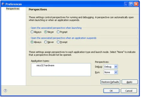
1. From within a given perspective, choose Window > Preferences. The Preferences window opens.
2. From the Preferences window, expand the General category on the left and select Perspectives.
The Perspectives preferences page opens.
3. From the Available perspectives list, select the desired perspective and click Delete.
4. Click OK.
USINGTHE LATTICEMICO SYSTEM SOFTWARE : LatticeMico System Software Overview
To change the default perspective:
1. From within a given perspective, choose Window > Preferences. 2. From the Preferences window, expand the General category on the left
and select Perspectives.
The Perspectives preferences page opens.
3. Select the perspective that you want to define as the default and click Make Default.
The default indicator moves to the perspective that you selected. 4. Click OK.
Resetting Default Perspectives
After customizing default perspectives, you can revert back to the original set of command options for a given perspective by resetting them in the software. To reset your default perspectives:
1. From within a given perspective, choose Window > Reset Perspective. 2. In the Reset Perspective pop-up dialog box, click OK.
This action returns all default perspectives back to their original option settings.
Closing and Opening Views in Perspectives
In each perspective, views are defined for each perspective that allow you to interactively perform a task. These views are described later in this chapter for each perspective.
At times, you may want to close views to make more space for working in a desired view. For example, after you add all of the components that you need in your platform, you may opt to close the Available Components view in the MSB perspective.
To close a view in a given perspective:
In a given perspective, click on the Close icon that appears as an “X” at the upper right corner of the view that you wish to close.
The view closes. In some cases where the two views did not overlap, an adjacent view moves into the vacated area in the interface, making the adjacent view larger.
To reopen a view that you previously closed:
In a given perspective, choose Window > Show View and select the view that you wish to reopen from the submenu.
USINGTHE LATTICEMICO SYSTEM SOFTWARE : Using C/C++ SPE to Develop Your Software
Using C/C++ SPE to Develop Your Software
After creating your hardware microprocessor platform, you must create the software application code that defines how it processes data. This section outlines how to use the LatticeMico C/C++ Software Project Environment (SPE), the primary tool that you use to develop your microprocessor
application code. You do tasks that use C/C++ SPE in the C/C++ perspective in the user interface.
The C/C++ perspective enables you to do the following tasks: Create and build new LatticeMico C/C++ software projects. Develop and compile your software application code to create
executables using its workbench.
Test or debug your software application code by directly analyzing the development board.
Access software deployment options such as deploying to on-chip memory or a parallel flash device.
Launch iProgrammer configuration software for downloading the FPGA bitstream to a hardware target device.
Starting C/C++ SPE
C/C++ SPE is another functional part of LatticeMico System, and you can access its commands in the C/C++ perspective. You can also access C/C++ commands from other perspectives. See “LatticeMico System Perspectives” on page 10 to understand how command options for various functional parts of the software are accessed in the software.
Before opening the C/C++ perspective, have the software running, as described in “Running LatticeMico System” on page 10.
To open the C/C++ perspective:
From the default MSB perspective, click the C/C++ activation button at the top left.
Alternatively, you can choose Window > Open Perspective > C/C++.
USINGTHE LATTICEMICO SYSTEM SOFTWARE : Using C/C++ SPE to Develop Your Software
The C/C++ perspective now becomes active and enables you to access C/C++ SPE commands. The current active perspective is shown in the upper left of the window’s title bar, as shown in Figure 5.
The C/C++ perspective consists of the following views:
C/C++ Projects view, which lists C/C++ SPE projects that have been created
Navigator view, which shows all of the file system files under the workspace folder
Editor view, which displays your editable files in the window. Each file is displayed within a separate tab within the view.
Outline view, which displays the structure of the file currently open in the Editor view. See the online Help for more details.
Problems view, which displays error, warning, or informational messages output related to your build
Console view, which displays informational messages output by the C/C++ SPE build process
Properties view, which displays the attributes of the item currently selected in the Projects view. This view is read-only.
Figure 5: C/C++ Perspective
Editor View
Outline View C/C++
Projects View
Problems View, Console View (shown), Properties View, Search View
USINGTHE LATTICEMICO SYSTEM SOFTWARE : Using C/C++ SPE to Develop Your Software
Search view, which displays the results of a search when you choose the Search > Search menu command
Tasks view, which shows the tasks running concurrently in the background Make Targets view, which allows you to create your own custom
makefiles. This ability is not necessary for managed make projects. Clicking the “X” icon next to the View title closes the selected view. To reopen a view that you previously closed, choose Window > Show View and the desired view submenu option. For a detailed explanation of the available views, refer to the online Help.
Creating Software Projects
There are three main types of software projects: LatticeMico managed make C/C++ project LatticeMico library project
LatticeMico standard make C/C++ project
A LatticeMico managed make C/C++ project is the easiest to use for getting started, because it manages the build environment, including linker scripts, boot code, sources, header files, and even makefiles. It also extracts platform-dependent information from the LatticeMico32 microprocessor platform and creates the appropriate files required for a build.
The LatticeMico library project and the LatticeMico standard-make project are described in “Advanced Programming Topics” on page 175. These two project types enable you to create your own build environment in which you can provide the desired make structure, as well as make files. This document refers to the managed-build process for all topics unless explicitly stated otherwise.
Creating a project is the first step in using C/C++ SPE. You select a target platform generated by MSB in the .msb file that you already created and create the software application code that controls the microprocessor and attached components. At the same time, C/C++ SPE generates system libraries based on the MSB platform, your selections, or both. Use the File > New >Mico Managed Make C/C++ Project menu command to create a software project.
Before using C/C++ SPE, you must define an MSB platform to select the Note
The folder in which the C/C++ SPE project is saved cannot reside at the same directory level as the folder in which the MSB project is saved. The C/C++ SPE folder can reside at a higher or lower directory level than the MSB project folder.
USINGTHE LATTICEMICO SYSTEM SOFTWARE : Using C/C++ SPE to Develop Your Software
components used by the software application code must reside in both platforms to ensure a successful build.
To facilitate development, you can select a project template to use in creating the software application code in C/C++ SPE and then modify this code. But once you create a project, you cannot change the template, because some templates have platform dependencies.
To create a new software project:
1. From the MSB perspective, click the C/C++ button in the upper left. The C/C++ perspective opens.
2. In the C/C++ perspective, choose File > New >Mico Managed Make C/ C++ Project.
The New Project dialog box opens, as shown in Figure 6.
3. In the Project Name box, enter the name of your new project. The Location text box points the top-level project folder where your software project’s contents will be stored, including your sources as well as the managed build files. The name of your project is automatically appended to the default folder location. To override the default assignment, first enter the project name and then enter the desired location.
USINGTHE LATTICEMICO SYSTEM SOFTWARE : Using C/C++ SPE to Develop Your Software
4. In the MSB System text box, browse to the location of the .msb file, select the .msb file, and click Open.
This file is located within this MSB platform folder, where there will be an \soc folder that contains an .msb file.
If you switched to C/C++ after opening an MSB platform or creating a new MSB platform, the MSB platform selection will, by default, contain the file name and path of that MSB platform description.
5. In the Select Project Templates list box, select the template for the application code.
This list box allows for selection of available software templates for a quick start on software development. Software templates provide a collection of software project files that are copied into your project’s folder. These provide you a starting point for creating your application. If you intend to create a blank project that contains no pre-existing files, select the blank project template. The Templates Description box provides information on selected platform component requirements and other relevant
information. 6. Click Finish.
Your software project has been created.
Your new project will appear in the C/C++ Projects view.
7. Click on the project nameto select it in the C/C++ Projects view on the left.
8. Choose Project > Build Project.
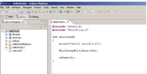
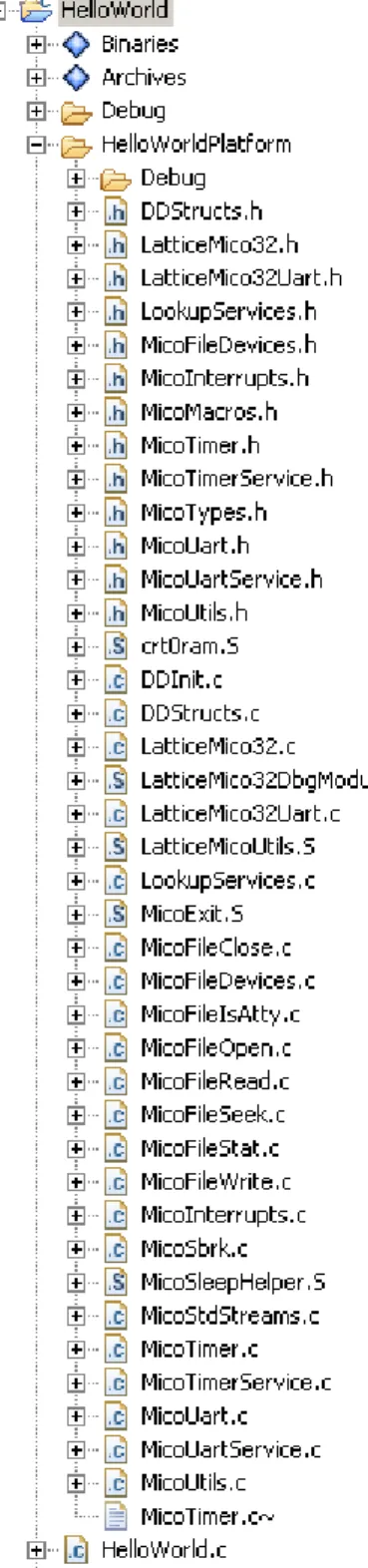
If you had selected a project template of the “hello world” variety during project setup, you would get the HelloWorld Projects view, as shown in Figure 7. The project folder in the view is shown expanded for illustrative purposes.
As you can see in Figure 7, this project contains source files copied over as part of the template specification. Subsequent parts of this document describe the relevant project files, such as the ones shown here. See “Managed Build Figure 7: Hello World Projects View
USINGTHE LATTICEMICO SYSTEM SOFTWARE : Using C/C++ SPE to Develop Your Software
Basic Project Operations
This section describes some of the most commonly used operations for project development. The C/C++ SPE software enables you to perform a given operation in various ways, such as selecting from a pop-up menu or selecting from the application menu. This section describes the most common ways of performing these operations.
Adding New Source Files or Folders
This section describes how to add new source files and folders to your C/C++ SPE project. Source files refer to .c files that contain your C programming code and are input into the C compiler to generate your object files. Source folders refer to directories that contain a host of .c files. Adding or creating a resource file in your project can refer to any file.
To add new source files to your C/C++ project:
1. In the C/C++ perspective, click on your project in the Projects view to select it.
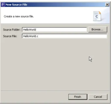
2. Right-click on the project icon and choose New > Source File from the pop-up menu.
3. In the New Source File dialog box, browse to your source file and click Finish.
To add new source folders to your C/C++ project:
1. In the C/C++ perspective, click on your project in the Projects view to select it.
2. Right-click on the project icon and choose New > Source Folder from the pop-up menu.
3. In the New Source Folder dialog box, browse to your source folder and click Finish.
To add new file resources to your C/C++ project:
1. In the C/C++ perspective, click on your project in the Projects view to select it.
2. Right-click on the project icon and choose New > Source File from the pop-up menu.
3. In the New File dialog box, browse to you source folder and click Finish. Note
LatticeMico C/C++ SPE is derived from Eclipse CDT, so basic project operations that apply to the Eclipse CDT perspective also apply to LatticeMico C/C++. Refer to the LatticeMico online Help for details on all available project manipulation operations.
USINGTHE LATTICEMICO SYSTEM SOFTWARE : Using C/C++ SPE to Develop Your Software
You can create subfolders within your project folder for organizing your source files. The managed build environment copies in the source files from these subfolders during the build process.
Deleting Software Project Contents
You can delete selected project contents in the Projects view. Deleting a project item does not erase the file from your hard disk. It simply deletes the visible project item in the C/C++ SPE interface.
To delete a C/C++ software project item:
1. In the C/C++ perspective, click on the project item in the Projects view to select it.
2. Right-click on the project it and choose Delete from the pop-up menu. This deletes the item from project definition, but not from your hard disk.
Renaming Software Project Contents
You can rename selected project contents in the Projects view. This section describes how to rename project items. Renaming a project item does not change its name on your hard disk. It simply changes the visible name of the project item in the C/C++ SPE interface.
To rename a C/C++ project item:
1. In the C/C++ perspective, click on the project item in the Projects view to select it.
2. Right-click on the project it and choose Rename from the pop-up menu. The project icon’s title box appears highlighted. It is editable.
3. Type the desired new name of the project item and click anywhere outside of the highlighted field or click Enter.
The new name is established.
Adding Existing Files/Folders to a Project
You can add existing files or folders to your C project using Windows Explorer by directly copying and pasting or dragging and dropping them into your project.
To copy and paste existing files or folders into your software project: 1. In Windows Explorer, right-click on the files, folders, or both that you wish
USINGTHE LATTICEMICO SYSTEM SOFTWARE : Using C/C++ SPE to Develop Your Software
If you wish to copy multiple files or folders, you can select them by using the Shift-click or Ctrl-click functionality.
2. In the C/C++ perspective's Projects view, right-click on the project folder and choose Paste from the pop-up menu or use the Ctrl+V keyboard combination.
The file or folder appears in the hierarchy underneath the project folder. To drag and drop files and folders into your software project:
1. In Windows Explorer, click on the files or folders or both that you wish to copy into your project. You can select multiple files for copying at once using the Shift-click or Ctrl-click functionality.
2. Drag the files over into your C/C++ perspective's Projects view onto a project folder until you see a plus sign on a “mouse over” with your cursor. 3. Release the mouse button.
The selected files or folders are copied into the targeted folder in the Projects view.
Deleting a Project
If you have created projects in your LatticeMico workspace that you want to remove, you can delete them from the Projects view.
To delete a software project:
1. In C/C++ perspective's Projects view, right-click on the folder of the project that you want to delete.
2. In the pop-up menu, choose Delete.
The Confirm Project Delete dialog box shown in Figure 8 now asks you if you are certain that you want to delete the project in the event that you selected this option by accident.
3. Click Yes.
USINGTHE LATTICEMICO SYSTEM SOFTWARE : Using C/C++ SPE to Develop Your Software
If you select the option button to delete the contents of the folder as well, the project is deleted from your workspace on your hard disk, as well as from your Projects view.
By default, as shown in Figure 8, the “Do not delete contents” option is selected. It only removes the folder in the Projects view. If you just remove the project from the Projects view, you have the option of importing the project back into your workspace later.
Importing an Existing Project
You can use the Import Wizard to copy a project from a different workspace or copy a project that previously existed in your workspace and import it into the LatticeMico software workbench. You cannot import a project that has the same project name as an existing project into the Projects view.
To import an existing project:
1. From within a given perspective, choose File > Import. You can also right-click on your project icon in the Projects view and select Import from the pop-up menu.
The Import dialog box opens in Select mode, as shown in Figure 9. Figure 9: Import Dialog Box in Select Mode
USINGTHE LATTICEMICO SYSTEM SOFTWARE : Using C/C++ SPE to Develop Your Software
The Import dialog box changes to Import Projects mode, as shown in Figure 10.
3. Choose either Select root directory or Select archive file and click the associated Browse button to locate the folder or file containing the project that you wish to import.
4. Under Projects, select the project or projects that you would like to import. 5. Click Finish to start the import.
If the project is successfully imported, it will appear in the Projects view.
Understanding the Build Process
Once you develop the software application code, you must compile and link it to generate an executable.
Building a project involves compiling, assembling, and linking the software application code, as well as the system library code generated by the C/C++ SPE. Each step in this process has associated settings that affect the build. A group of such settings is called a build configuration.
Typically you might expect a default build configuration for building software application code that can be debugged. You might also expect a default build configuration for building optimized software application code that is
USINGTHE LATTICEMICO SYSTEM SOFTWARE : Using C/C++ SPE to Develop Your Software
unsuitable for debugging with a debugger tool because it may contain optimized code and may not include debug symbols.
A newly created C/C++ SPE project provides two default configurations: A debug build configuration for generating an executable that can be
debugged
A release build configuration for generating an optimized executable devoid of any debug information
The build process involves creating makefiles and then performing a make operation on the top-level makefile that, in turn, pulls in the required makefiles. This process creates makefiles for the software application code structure (typically subfolders for code organization) and creates makefiles for the platform library.
The linker settings depend on the MSB platform for locating the various compiler-dependent sections, for example, the text section that contains the executable code. These section settings become especially important for platforms that contain multiple memory components. The LatticeMico System managed project enables you to make selections for the location of the executable section, read-only data section, and read/write data section. The section settings are updated when a change to the MSB platform file is detected and when you attempt to access the section setting. If the .msb file changes and the application is built without accessing the sections settings, the build will fail if the user-selected section memory does not exist in the updated .msb file.
The system library settings, as well as the linker section settings, are the same for all build configurations.
Building Your Software Project
This section describes how to build your software project, that is, to create all of the necessary files that you must have in place to properly deploy your software application code.
USINGTHE LATTICEMICO SYSTEM SOFTWARE : Using C/C++ SPE to Develop Your Software
To build your project:
1. In the C/C++ perspective, right-click the desired project folder in the Projects view on the left. In the example in Figure 11, the highlighted project folder in the Projects view is called HelloWorld.
2. In the pop-up menu, choose Build Project. Alternatively, you can build a project by choosing the Project > Build Project menu command, as illustrated in Figure 11.
If the build has potential warnings or errors, Eclipse CDT might place an information icon next to the project folder in the Projects view.
The Console view in the C/C++ perspective displays the project build messages. The Problems view in the C/C++ perspective displays problems encountered during the build. Along with other icons, the Problems view may display a warning or error icon:
The warning icon indicates that there was an associated warning message that was generated by the build process.
The error icon indicates that there was an associated error message generated by the build process.
For a complete list of icons in the user interface that may be displayed and their meanings, refer to Eclipse/CDT and the LatticeMico System online Help.
Setting Project Properties
You can set up your project properties in the Properties dialog box. Project properties include various project parameters, for example, file encoding parameters, build configuration options, and platform settings. The Project Property dialog box is dynamic in that it enables you to select different “tabs” from the list box at left, which changes the display parameter set in the main option area of the dialog box.
USINGTHE LATTICEMICO SYSTEM SOFTWARE : Using C/C++ SPE to Develop Your Software
To set project properties:
1. In the C/C++ perspective, right-click the desired project folder in the Projects view on the left. In the example in Figure 11 on page 26, the project is entitled HelloWorld.
2. In the pop-up menu, choose Properties.
The Properties dialog box appears, as shown in Figure 12.
The Properties dialog box enables you to set the C/C++ build settings through the C/C++ build tab and the platform preferences through the Platform tab. See the list box on the left side of the Properties dialog box, as shown in Figure 12.
USINGTHE LATTICEMICO SYSTEM SOFTWARE : Using C/C++ SPE to Develop Your Software
The C/C++ build tab, as shown in Figure 13, enables you to set build properties for the project.
The C/C++ build tab enables you to set compiler and linker options for a given build. This tab contains several options:
Configuration Setting – This option allows you to select the active build configuration, as well as to modify the default settings. It also enables you to define your own configurations. LatticeMico C/C++ SPE uses the GNU C/C++ tool chain for project compilation and linking. A set of C/C++ build settings is known as a build configuration.
The C/C++ SPE has two predefined configurations, Debug and Release. The default Debug build configuration is set to maximize debug visibility with compiler optimizations turned off. The release configuration is set to maximize program efficiency with no debug visibility. To define your own configurations, refer to the Eclipse CDT documentation.
Tool Setting– This tab enables you to view or modify the compiler or linker settings, the run-time library, and printf selections.
"Use Small-C" and "Use standalone small-printf" affect the run-time C library selection and the printf selection, respectively. These two options are described in “Run-Time Libraries” on page 45.
"System Library Settings same as application" enables you to select application compiler settings and use these settings as system library compilation settings. You can apply separate compiler settings for the application and the system library build by clearing this option and selecting appropriate settings. The system library build is part of the managed build process described in “Managed Build Process and Figure 13: C/C++ Build Tab of Properties Dialog Box
USINGTHE LATTICEMICO SYSTEM SOFTWARE : Using C/C++ SPE to Develop Your Software
Directory Structure” on page 145. The LatticeMico linker settings affect the generation of the application executable.
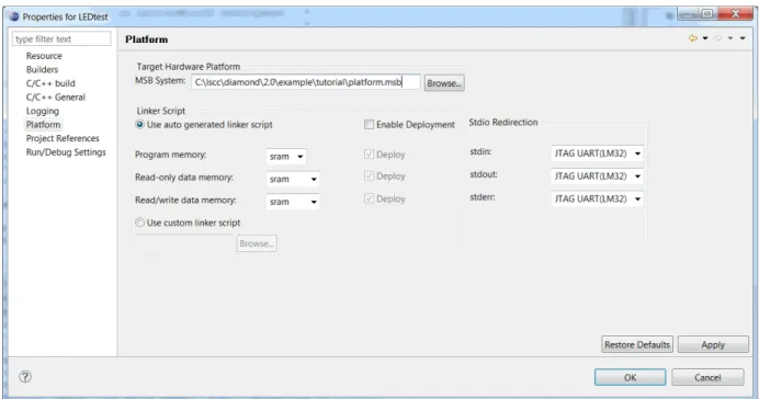
Figure 14 shows the platform settings that are accessible in the Platform tab of the Properties dialog box.
The Platform tab is further subdivided into the following fields:
Target Hardware Platform – This option shows the currently selected platform for the selected project in the MSB System text box. You can retarget this software application to another platform by using the Browse button to select the appropriate platform. You must make sure that the platform that you select and your software applications are compatible with each other.
Linker Script – By default, C/C++ SPE always generates a linker script usable for linking the selected project. This default linker script is generated on the basis of the selected platform.
You can provide your own linker script by selecting the Use Custom Linker Script button. If you use the default linker script generated by C/C++ SPE, you can choose the memories in which different linker sections will be placed. C/C++ SPE explores the selected platform and identifies memory components and their attributes, making them available for user selection in this field.
Program Memory – This memory, which can be a read/write memory Figure 14: Platform Tab of the Properties Dialog Box
USINGTHE LATTICEMICO SYSTEM SOFTWARE : Using C/C++ SPE to Develop Your Software
Read Only Data Memory – This memory, which can be a read/write memory or a read-only memory, contains the read-only application data.
Read/Write Data Memory – This memory contains read/write data required by the program, as well as the microprocessor stack and application heap. C/C++ SPE makes available only those memories marked as read/write. Memories marked as read-only are not made available by C/C++ SPE.
Whether you choose to use the default linker script or provide your own, C/C++ SPE always generates a default linker script.
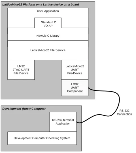
Stdio Redirection – This group of options enables you to select an appropriate file device to handle standard input/output requests from the software application.
The C/C++ SPE inspects the .xml file of each component included in the platform to identify which components are capable of handling the standard input/output streams. Refer to the section “Creating Custom Components” in the LatticeMico32 Hardware Developer User Guide for instructions on how to make a component instance available for handling standard input/output operations through this Platform tab.
In addition to marking the component description file to make the device appear in this Platform tab selection, the component-specific software must be configured as a file device to handle file-operation requests from the LatticeMico File Service. Refer to “LatticeMico File Service” on page 98 for details on the LatticeMico File Service and how to create a file device.
Rebuilding Your Software Project
After you create your project, you can perform subsequent builds by right-clicking the project name in the C/C++ perspective’s Projects viewand choosing Build Project from the pop-up menu.
A release build configuration is for generating an optimized executable devoid of any debug information.
In the Eclipse/CDT, you can change the default settings that the C/C++ SPE remembers for the project, and you can create new build configurations with customized settings.
Performing Builds Automatically
You can set up the software workbench to automatically perform incremental builds whenever sources are saved.
To indicate that you want the software to perform incremental builds whenever resources are saved:
USINGTHE LATTICEMICO SYSTEM SOFTWARE : Using LatticeMico System as a Stand-Alone Tool
The workbench automatically performs incremental builds of resources modified since the last build. Whenever a resource is modified, another incremental build is run.
Using LatticeMico System as a Stand-Alone Tool
The software developer can use C/C++ SPE to develop software application code without having to install Lattice Diamond, as long as the directory structure and appropriate files have been provided by the hardware developer. The files that the hardware designer provides to the software developers are the Mico System Builder project file, the LatticeMico32 microprocessor driver files and GNU files, the component driver files, and the FPGA's configuration bitstream.
The hardware developer needs to have both Diamond and LatticeMico System installed in order to generate the files and provide them to the software developer. The software developer needs Diamond Programmer installed, as well as LatticeMico System.
The following scenario shows the tasks involved:
Hardware Developer The hardware developer performs the following tasks:
1. Uses Lattice Diamond to create an FPGA development project.
The Diamond software is used to generate the FPGA bitstream containing the LatticeMico32 microprocessor and peripherals.
2. Generates the platform for the project using LatticeMico System Builder. 3. Imports the platform’s RTL source files into the project in Diamond and
USINGTHE LATTICEMICO SYSTEM SOFTWARE : Running the Debugger on Your Code
4. Sends all software developers the Mico System Builder project directory. For example:
5. Sends the software developers the FPGA bitstream file (.bit) that was generated using Diamond.
Software Developer The software developer performs the following tasks: 1. Uploads the files sent from the hardware developer:
a. Launches the LatticeMico Mico System Builder.
b. Loads the <platform_name>.msb file provided by the hardware engineer.
2. Creates a new managed make or standard make project in C/C++ SPE. 3. Implements the LatticeMico32 firmware.
4. Compiles the LatticeMico32 firmware using the Project > Build all command.
5. Runs and debugs the application.
Running the Debugger on Your Code
You can run the Debugger as described in the following procedure, and as shown in Figure 15 on page 33.
To use the Debug perspective to run the Debugger on your code: In the upper left-hand corner of the MSB graphical user interface, select
the Debug activation button to switch to the Debug perspective. Alternatively, you can choose Window > Open Perspective > Debug.
USINGTHE LATTICEMICO SYSTEM SOFTWARE : Running the Debugger on Your Code
To run the Debugger tool from within the C/C++ perspective:
1. In the Projects view of the C/C++ perspective, click on the project folder nameto select and choose Run > Debug Configuration.
2. To create a new configuration, click the New launch configuration icon on the toolbar above the left pane.
The Debug dialog box now appears with hello_world_0 highlighted. 3. In the Debug dialog box, click Debug.
4. In the Confirm Perspective Switch box, click Yes. The Debug perspective consists of the following views: Debug view, which displays the function calls made so far
Variables view, which displays the variables that are used in the source code functions
Breakpoints view, which appears when you insert a breakpoint Figure 15: Debug Perspective
USINGTHE LATTICEMICO SYSTEM SOFTWARE : Running the Debugger on Your Code
Console view, which displays the output of the debugging session Tasks view, which is not used
Modules view, which displays the modules of the executable loaded. If you click on a module, C/C++SPE displays all the functions that compose that module.
Registers view, which displays the registers in the CPU. It also shows the values on the registers at the breakpoints. Values that have changed are highlighted in the Registers view when your program stops.
Signals view, which enables you to view the signals defined on the selected debug target and how the debugger handled each one
Memory view, which enables you to inspect and change multiple sections of your process memory
Expressions view, which is activated if you right-click in the Source view, choose Add Watch Expression, and enter a variable in the Add
Expression dialog box
Disassembly view, which shows the source code in assembly language with offsets. It shows the instructions that reside at each address.
Clicking the “X” icon next to the View title closes the selected view. To reopen a view that you previously closed, choose Window > Show View and the desired view submenu option. For a detailed explanation on the available views, refer to the online Help.
Debugging and Executing Your Code
C/C++ SPE provides a GUI-based debugging environment. It uses the GNU GDB debugger for controlling program execution and debug activities. It also uses a Lattice Semiconductor-provided application to facilitate a
communication channel between the LatticeMico32 microprocessor debug module and GDB. You can choose either to run the application or to debug the application.
For information about performing functional simulation of a LatticeMico32 platform, refer to the LatticeMico32 Hardware Developer User Guide.
C/C++ SPE provides two means of exercising the final executable:
Debugging the software application code. To debug your application, the LatticeMico32 microprocessor instance in your platform must have the debug capability turned on. Additionally, you must enable generation of debug symbols (–g2 or –g3 compiler option) when compiling your application, as is done for the default debug build configuration. For a thorough debug session, you should disable compiler optimizations (-O0) so that the compiler does not rearrange the code.
Note
It is important that the platform generated using MSB include a CPU with its debug option enabled so that C/C++ SPE can download and debug an application.
USINGTHE LATTICEMICO SYSTEM SOFTWARE : Running the Debugger on Your Code
When you debug an application, the C/C++ SPE perspective changes to the Debug perspective, which provides views for inspecting CPU
registers, watching disassembled code, watching the stack trace, and so forth. Debugging typically allows you to “pause” the application being debugged and to place a breakpoint at a predefined symbol to stop execution at a predetermined location when it downloads and runs the code.
Running the software application code. When you run the software application code, C/C++ SPE simply downloads the executable and executes it without changing the view. It does not insert any breakpoints and executes the code without allowing you to debug the application. C/C++ SPE requires information about the target connection (for example, JTAG), the executable to be used, debug information (for example, the choice of breaking at a predetermined symbol), and the source location for a debug session. This collection of information forms a target configuration.
C/C++ SPE provides one target configuration for a JTAG connection to the target that you can use without having to enter or modify the default settings. If you are an advanced user, you can modify the default settings. The created configurations are saved so that you do not have to recreate the configuration for a given project every time.
To run a debug session:
1. In the C/C++ perspective’s Projects view, click the Project folder name to select it and choose Run > Debug.
The Debug dialog box now appears, as shown in Figure 16. It enables you to choose your target connection from the configurations list on the left
USINGTHE LATTICEMICO SYSTEM SOFTWARE : Running the Debugger on Your Code
2. In the sentence on the bottom right, click the Perspectives link to open the Perspective dialog box, shown in Figure 21
3. The Perspectives dialog box enables you to specify the associated perspective for this instance of the launch configuration. You should not change the associated perspective selection (set to Debug in Figure 17) for debug sessions, because the Debug perspective provides a complete debug environment.
3. Click OK to return to the Debug Configuration dialog box.
4. In the target configuration list on the left, select the desired target configuration—mico32 hardware.
5. Click the “New launch configuration” button on the toolbar to create a launch configuration based on your selections.
USINGTHE LATTICEMICO SYSTEM SOFTWARE : Running the Debugger on Your Code
The dialog box changes, displaying the configuration tabs, as shown in Figure 18.
This dialog box includes the following tabs:
Main tab – You select the project and its associated executable in this tab. Only those projects that are part of the C/C++ Projects view are available for selection. However, you can choose an executable (.elf) file that may or may not be associated with the selected p roject. If you launched the Debug configuration after selecting the project you wish to debug, the options in this tab will contain default settings based on the selected project. You must make sure that the appropriate C/C++ application is selected if you have multiple applications for the same project.
Hardware Connection tab – This tab is available only for the mico32 hardware configuration. It enables you to specify a scan chain Figure 18: Main Tab of Debug Dialog Box
USINGTHE LATTICEMICO SYSTEM SOFTWARE : Running the Debugger on Your Code
configuration (.xcf) file generated by Diamond Progammer when you want to program devices in a JTAG daisy chain.
Debugger tab – The default debugger settings are configured appropriately and generally should not be modified. You can specify whether you want your initial breakpoint at the application main routine Figure 19: Hardware Connection Tab
USINGTHE LATTICEMICO SYSTEM SOFTWARE : Running the Debugger on Your Code
(main()) or at the device driver initialization routine (LatticeDDInit) that is called before the application main routine.
Additionally, you can always open the appropriate source file in the C/C++ perspective and put in a breakpoint before launching a debug session. The Remote Target option specifies the address that GDB will use when connecting to the Lattice Semiconductor-provided target communication executable. You should not modify the default setting for this field.
Source tab – By default, this tab contains all the necessary information for a debug session. It enables you to specify any additional folder or source that the Debugger should look up to find source information. By design, all source files pertaining to the C/C++ SPE device driver framework are contained within the project, as discussed in
subsequent chapters of this document. Figure 20: Debugger Tab of Debug Dialog Box
USINGTHE LATTICEMICO SYSTEM SOFTWARE : Running the Debugger on Your Code
If you have source files that do not reside within the C/C++ project, you can provide lookup paths for the Debugger through this tab.
After you have configured the appropriate tabs, click the Apply button to save the debug launch configuration that you have defined for future use. For additional information, refer to the Eclipse/CDT documentation. 6. Select the appropriate launch configuration in the Configurations list box
on the left.
If you have multiple launch configurations, you must select an appropriate launch configuration before starting a debug session.
7. In the Debug dialog box, click Debug.
8. In the Confirm Perspective Switch box, click Yes.
This procedure activates the Debug perspective and downloads the .elf file into the FPGA. In addition, the Debug perspective allows a more robust Figure 21: Source Tab in Debug Launch Configurations