65
Evaluation of the Performance of Underwater
Wireless Sensor Networks Routing Protocols under
High-density Network
Nasarudin Ismail & Mohd Murtadha Mohamad
School of Computing,Faculty of Engineering Universiti Teknologi Malaysia, 81310 UTM Johor Bahru, Johor, Malaysia
Email: [email protected]
Submitted: 23/07/2019. Revised edition:20/10/2019. Accepted: 22/10/2019. Published online: 28/11/2019 DOI: https://doi.org/10.11113/ijic.v9n2.237
Abstract—Nowadays, research and development of Underwater Wireless Sensor Networks (UWSNs) widely supporting various available application such as oil/gas monitoring system, tsunami monitoring, disaster prevention, and environmental monitoring has become increasingly popular among academicians and industries. However, to develop efficient communication in UWSNs is a difficult duty due to the irregular nature of the underwater environment. In our previous review [14], we did an elaborate theoretical survey on UWSNs routing protocols. In this work, we are going to evaluate the performance of some of the UWSNs routing protocols under high-density network condition. To simulate a high-density UWSNs, we are placing hundreds of underwater nodes in a small three-dimensional topographical area and study the behavior of the routing protocol and the network. We have chosen to evaluate some of the frequently addressed underwater routing protocols such as Underwater Flooding (UWFlooding), Vector-Based Forwarding (VBF), and Hop by Hop Vector-Based Forwarding (HH-VBF) under this high-density network scenarios. The result of our study shows that VBF and HH-VBF perform better in term of the number of packets received, dropped packets and PDR, while UWFlooding performs better in term of cumulative delay.
Keywords—Opportunistic routing, aquasim, UWSNs, routing
protocols, flooding
I.INTRODUCTION
Due to the successful exploration of the knowledge of the land and its structure, thanks to the development of
technology in the Wireless Sensor Network (WSN) has given a similar inspiration to researchers in the underwater area. Therefore, researchers are keen to explore underwater environments with the same technology that can be called Underwater Wireless Sensor Networks (UWSNs) [1]. However, because the underwater environment has unique features such as high water pressure, wide area and environmentally abusive conditions, the use of UWSNs without any human involvement is the most appropriate way [2].
Due to the land and underwater environment have numerous differences in characteristics, UWSNs cannot directly apply the established technology design for land which is Terrestrial Wireless Sensor Networks (TWSNs). One of the hottest research topics at UWSNs is routing protocol design which can promise the consistency and effectiveness of the communication of packet data from the source nodes to destination nodes. This designing routing protocol, until now is one of the key issues in UWSNs [3–5].
66 Due to the distinctive characteristic of the underwater environment, designing the routing protocol for communication network in UWSNs is tough challenge. First the distribution area in UWSNs is so enormous which is using three-dimensional architecture. Nevertheless, the nodes are usually deployed in sparse area because they are more expensive as compared to TWSNs [7]. Second, sensor nodes in UWSNs are solely run by the battery, compared to TWSNs nodes which can use solar to prolong the power, which unable to recharged and swapping them are also challenging because of water situation [1].
Lastly, in UWSNs caused by the irrelevant usage of Global Position System (GPS) signal because in the underwater, high radio frequency is quickly absorbed, so assigning and to receive and share the sensor node location information is very challenging task in UWSNs compared to TWSNs [2, 7, 8].
The remainder of this paper is structured as follows. Section II discusses the challenges in Design UWSNs. Section III will overview on Modeling Acoustic UWSNs. Section IV presents our study for the performance of UWSNs routing protocol under high-density network. Finally, Section V presents our result and conclusion of this study.
II.CHALLENGES IN DESIGNING UWSNS
Generally, the implementation of UWSNs has various problems and challenges. The important issues in UWSNs include communication, security, energy, node mobility, dynamic network topology, and routing.
a. Communication
Unlike TWSNs that use radio frequency to communicate among nodes, UWSNs use acoustic wave to communicate. While for UWSNs, the acoustic wave is more suitable to use for communicate among nodes. Due to low signal dampening in water, the acoustic wave is the most suitable especially in the deep ocean water environment. However, in shallow water, the acoustic communication is bothered by temperature gradients, surface noise and multipath propagation due to refraction and reflection[9]. Due to the significant latency delays in UWSNs acoustic communication, network congestion is one of the potential problem in cases where network latency is high.
a. Power Resources
Sensor nodes in TWSNs have the ability to be recharged and powered by solar energy in the wake of low power availability. However, in an underwater environment, the sensor node of UWSNs cannot afford to be recharged or powered by solar energy due to unavailability of sunlight in deep water environment. Therefore, most of time the sensor node in UWSNs is solely powered by the battery.
b. Network Topology
Node movement is a critical issue in UWSNs compared to TWSNs where usually, TWSNs nodes are static in their position. Nodes deployed in a UWSNs are more vulnerable to position adjustment because of water current flow. While it may not be a significant issue in deep waters, but in shallow waters, the node movement is a major issue considering floating nodes (on the water surface) and nodes deployed near to water surface. According to [12], underwater objects might drift at the speed of 2-3 knots (3-6 Km/hr) in a conservative underwater environment. Despite research which has been carried out widely on UWSNs, node movement issue has not been addressed completely. Thus, UWSNs must adapt dynamically to the changes in the nodes and network topology. The network itself must be self-learning in order to adjust to the new topology
c. Security
Though security in TWSNs has been advanced [18], research in UWSNs security is still in early stages [19]. Energy sources are limited in powering UWSNs node could impact on any introduction robust security technique as the power node will quickly run out. Research in security for UWSNs will be key to develop better and secure underwater applications using sensor networks. Due to the power required to process cryptic messages (encryption and decryption), this technique needs to be studied extensively before the appropriate security techniques can be used in UWSNs. Many challenges must be addressed first in safeguarding UWSNs including data confidentiality, data integrity, encryption of encrypted messages, secure localization and nod authentication for secure message delivery.
III.FEATURE OF ACOUSTIC UWSNS
There are several features of acoustic UWSNs.
A.High Propagation Delay
The speed travel of the acoustic wave in water is around 1500m/s, which explains for an enormous propagation delay (0.67 s/km). While for TWSNs, this delay is irrelevant because the radio frequency speed in the air is roughly 3∗108m/s, but on UWSNs, it has to be cautiously well-thought-out because of the enormous delay [7, 10, 11].
B.High Energy Consumption
67 communication among sensor node[2, 4]. Furthermore, due to the uncertain current flow of water, the UWSNs node is experiencing endless mobility which leads to broken communication, multipath decreased and packet drops. All of these problems can result to repetitive of packets transmission, which can add a lot of power to UWSNs nodes. Usually the power consumption for broadcasting typically 125 times more than the power consumption of the reception [5, 10].
C.High Path Loss
In UWSNs, the attenuation is one of the main reasons for the path loss. The main reason for acoustic channel attenuation in underwater is because of absorption of acoustic signal due to exchanging acoustic energy to heat. The absorption damage in acoustics in the water is large compared to the radio frequency in the air and relies heavily on signal frequency and transmission distance [7, 8, 12]. Generally the path loss in UWSNs can be computed by the equation (1) which based on signal frequency and transmission distance [12].
A(l, f) = (l/lr)ka(f)l-lr, (1)
Where f is the frequency of the signal and l is the transmission distance, taken in reference to some lr. Model path loss exponent k transmission loss, and normal value is between 1 and 2 (for cylindrical and spherical dispersion, respectively).
D.Limited Bandwidth
Usually the bandwidth of UWSNs acoustic channels is limited and naturally be determined by the broadcast power and transmission distance, and radio frequency [13]. Usually lower frequency signals are used for long distances to avoid rapid absorption with water. Additionally, upper frequencies are used in short ranges to increase bandwidth and reduce errors.
Table I have shown the standard bandwidths of UWSNs Acoustic channel for different ranges.
TABLE I. The Available Bandwidth for Ranges in UWSNs Acoustic Channels
Range (KM) Bandwidth (KHz)
Very Long 1000 <1
Long 10-1000 2-5
Medium 1-10 ≈10
Short 0.1-1 20-50
Very Short <0.1 >100
IV.EVALUATION UWSNS ROUTING PROTOCOL UNDER HIGH -DENSITY NETWORK
In this section, we are going to study the performance of the most common UWSNs routing protocols under such challenging network condition. In this study, we will be using the Aqua-Sim[14] for the simulation tool. We will evaluate some of the selected UWSNs routing protocol available in Aqua-Sim and study their performance in high-density network condition and parameters. We will use suitable metrics to compare the performance of these routing protocols toward the high-density network.
Three available UWSNs routing protocol in Aqua-Sim, UWFlooding, VBF and HH-VBF. These three routing protocols are to evaluate their network performance by simulating the high number sensor node UWSNs deployment in small three-dimensional topographical areas.
A. UWFlooding
UWFlooding is a simple computer network routing algorithm in which every incoming packet is sent through every outgoing link except the one it arrives on. Flooding or opportunistic routing protocols is a reliable solution to deliver packets in UWSNs. However, these protocols potentially involve all the nodes in the forwarding process. Thus, the performance and energy efficiency are not optimal. UWFlooding is a normal flooding-based routing protocol that is designed to work with underwater traffic source and sink that include in Aqua-Sim.
B. VBF[15]
The VBF is a location-based routing protocol based on mobility and it is assumed that location of the sensor nodes is known. VBF is proposed to overcome the two main problems in the underwater environment, namely nonstop movement sensor nodes by uncertain flow of water and energy efficiency. In the implementation of VBF, each source node will generate its own virtual pipeline towards the receiver at water surface. As this protocol belongs to the receiver-based subcategory, all the sensor nodes are responsible for identifying their suitability to forward the data. After getting a packet, the sensor node which is less distant than the vector radius can transmit the packets by embedded the sender's node information, if not it only removes the packet
In the node transmission phase, only a few selected nodes are involved in the packet transmission. Since the involvement of the nodes are lesser, the energy consumption and network traffic load are drop extensively.
C. HH-VBF [16]
68 it uses a reduced radius range than VBF in determine appropriate forwarder nodes which a major enhancement in the packet delivery ratioHH-VBF uses a variety of virtual pipes from source nodes to destination nodes because HH-VBF works one-hop basis i.e. each forwarding node computes a vector from itself towards the sink. As this HH- VBF is also receiver-based, the qualified sensor node for forwarding is determined by the sensor node based on the radius range computed by the previous forwarder node.
On the other hand, due to the broadcast method hop-by-hop, network overhead is heavier than the VBF; Besides, the performance of HH-VBF is responsive to the minimum vector radius and HH-VBF also unable to handle void region areas same as VBF.
1)Simulation Setup
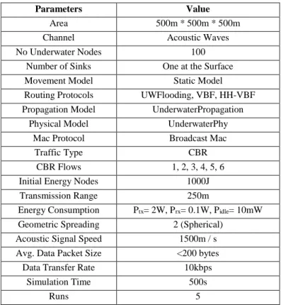
The sensor nodes are placed at the random location and some selected set of underwater nodes starts CBR traffic and send packets to the sink node which is at the surface of the water. Most of the parameters of the simulations were used as the default of Aqua-Sim. Table II shows the parameters that were used in this simulation. The simulations were repeated for several times and only the average values of results are taken into account. The randomness of the topology and network conditions, traffic start and stop time were controlled by seeding the random number generator with respect to the run number.
TABLE II.Some Important Parameters of the Simulation
Parameters Value
Area 500m * 500m * 500m
Channel Acoustic Waves No Underwater Nodes 100
Number of Sinks One at the Surface
Movement Model Static Model Routing Protocols UWFlooding, VBF, HH-VBF Propagation Model UnderwaterPropagation
Physical Model UnderwaterPhy
Mac Protocol Broadcast Mac
Traffic Type CBR
CBR Flows 1, 2, 3, 4, 5, 6 Initial Energy Nodes 1000J
Transmission Range 250m
Energy Consumption Ptx= 2W, Prx= 0.1W, Pidle= 10mW Geometric Spreading 2 (Spherical)
Acoustic Signal Speed 1500m / s
Avg. Data Packet Size <200 bytes Data Transfer Rate 10kbps
Simulation Time 500s
Runs 5
2)Metrics Used for Evaluating the Performance
To evaluate the performance of UWSNs routing protocols in the high-density network, the following metrics were considered:-
a) The number of Received Data Packets:
The number of the received packet at the sink is an important metric to measure the performance of the routing protocol.
b) The number of Dropped Data Packets at
Application Layer:
These are not actually dropped packets – these are the packets that cannot reach the sink because of overhead, delay, and other reasons. Simply it is equal to the number of sent data packets minus the number of received data packets at the sink.
c) Packet Delivery Ratio - PDR (%):
Packet delivery ratio is the percentage of the number of packets received by the sink node at the surface of the water to the total number of packets sent into the network by the UWSNs sensor nodes.
d) Cumulative Delay (milliseconds):
The average time interval between the generation of a packet in a source UWSNs node and the successfully delivery of the packet at the UWSNs sink node. It counts all possible delays that can occur in the source and all forwarding nodes, including queuing time, packet transmission and propagation delay, and retransmissions at the MAC layer. In this work, we are finding the average of the cumulative end-to-end delay of totally the data packets. It is measured in Millie- seconds.
V.RESULT AND CONCLUSION
69
A.Analysis of the Result
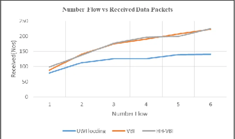
The following line graph shows the number of successfully receive data packets at the sink node due to the different number of traffic flows. As shown in Fig. 1, the performance of UWFlooding is poor and even getting very poor with respect to the increase in the number of traffic data flows from different source nodes. The performance of the VBF and HH-VBF routing protocols seems to be almost equal and giving an acceptable performance with respect to the increase in the number of traffic data flows.
Fig. 1. Number Flow vs Received Data Packets
The following line graph shows the number of data packets dropped an application layer with respect to the different number of traffic flows. As shown in Fig. 2, the performance of UWFlooding is poor and getting worst due to the increase in the number of traffic data flows from different source nodes. While for the performance of the VBF and HH-VBF routing protocols in terms of dropped data packets seems to be almost equal and a little bit better than UWFlooding but also getting worst as a result of the increasing number of traffic data flows from different source nodes.
Fig. 2. Number Flow vs Dropped Data Packets
The following line graph shows the performance in terms of PDR in consequence to the different number of traffic flows. As shown in Fig. 3, the performance of UWFlooding is poor and even getting more worst due to the increase in the number of traffic data flows from different source nodes. While for VBF and HH-VBF, for the early flow their performance seems to be almost equal and better than UWFlooding. But their performance is getting worst once there is an increase in the number of traffic data flows from source nodes.
Fig. 3. Number Flow vs Packet Delivery Ratio
The following line graph in Fig.4 shows the performance in terms of cumulative delay with respect to the different number of traffic flows. The performance of the HH-VBF routing protocols seems to be a little bit poor than VBF. While for the UWFlooding in terms of end to end cumulative delay, its perform better than the two other routing protocols and even almost constant irrespective of the number of flows.
Fig. 4. Number Flow vs Cumulative Delay
70 for most of the overheads involved in these protocols. So reducing the number of forwarding nodes will reduce these overheads.
VBF and HH-VBF are producing less overhead compared to UWflooding because of the reduction in the broadcast by doing broadcasts within a small ‘virtual pipe' which is the core idea of their routing protocol design.
The UWFlooding was able to provide very low end to end delay because of its vigorous nature of forwarding packets at each hop. But the same nature will also increase the other overheads. Even though we are expecting good performance in the case of HH-VBF from the theoretical point of view, practically it provided equal or little bit poor performance than normal VBF as per the most of the metrics. But in most of the cases, the normal VBF performed a little bit better than the HH-VBF protocol. The reason for this difference may be due to the additional overhead involved in the design of HH-VBF protocol.
B.Conclusion
In this paper, we try to evaluate the performance of UWSNs routing protocols in a high-density network scenario. From the result shows that all three routing protocol suffers from unreliable performance when there is more traffic flow in the high-density network scenario. Among them, the UWFlooding is the worst performer because the technique implies that routing protocols is just forward the packets. While for two other routing protocols, VBF and HH-VBF they share almost identical or much better performance among them.
In our future works, we will do an extensive study and evaluation on the available routing protocols and it might help to improve some of the existing routing protocol that apply a multiple sink node instead only one sink node to further study the effect on high-density network scenarios in UWSNs.
REFERENCES
[1] Akyildiz, I. F., Pompili, D., Melodia, T. Underwater Acoustic Sensor Networks: Research Challenges. (2005). Ad Hoc Networks, 3, 257-279.
[2] Ayaz, M., Baig, I., Abdullah, A., et al. (2011). A Survey on Routing Techniques in Underwater Wireless Sensor Networks. J Netw Comput Appl, 34, 1908-1927.
[3] Melodia, T., Kulhandjian, H., Kuo, L., et al. (2013). Advances in Underwater Acoustic. Mobile Ad Hoc
Networking: Cutting Edge Directions. Second
Edition, 804-854.
[4] Climent, S., Sanchez, A., Capella, J. V., et al. (2014). Underwater Acoustic Wireless Sensor Networks: Advances and Future Trends in Physical, MAC and
Routing Layers. Sensors (Basel), 14, 795-833. [5] Li, N., Martínez, J-F., Meneses Chaus, J., et al.
(2016). A Survey on Underwater Acoustic Sensor Network Routing Protocols. Sensors, 16, 414. [6] Zenia, N. Z., Aseeri, M., Ahmed, M. R. et al. (2016).
Energy-efficiency and Reliability in MAC and Routing Protocols for Underwater Wireless Sensor Network: A Survey. J Netw Comput Appl., 71, 72-85. [7] Akyildiz, I. F., Pompili, D., Melodia, T. (2004).
Challenges for Efficient Communication in Underwater Acoustic Sensor Networks. ACM
SIGBED Rev., 1, 3-8.
[8] Heidemann, J., Wei Ye, Wills, J., et al. (2006). Research Challenges and Applications for Underwater Sensor Networking. IEEE Wirel
Commun Netw Conf 2006 WCNC 2006, 00, 228-235.
[9] Lanbo, L., Shengli, Z., Jun-Hong, C. (2008). Prospects and Problems of Wireless Communication for Underwater Sensor Networks. Wirel Commun
Mob Comput., 8, 977-994.
[10] Partan, J., Kurose, J., Levine, B. N. (2007). A Survey of Practical Issues in Underwater Networks. ACM
SIGMOBILE Mob Comput Commun Rev., 11, 23.
[11] Chen, K., Ma, M., Cheng, E., et al. (2014). A Survey on MAC Protocols for Underwater Wireless Sensor Networks. IEEE Commun Surv Tutorials, 16, 1433-1447.
[12] Stojanovic, M., Preisig, J. (2009). Underwater Acoustic Communication Channels: Propagation Models and Statistical Characterization. IEEE
Commun Mag., 47, 84-89.
[13] Coutinho, R. W. L., Boukerche, A., Vieira, L. F. M.,
et al. (2016). Design Guidelines for Opportunistic
Routing in Underwater Networks. IEEE Commun Mag., 54, 40-48.
[14] Xie, P. X. P., Zhou, Z. Z. Z., Peng, Z. P. Z., et al. (2009). Aqua-Sim: An NS-2 based Simulator for Underwater Sensor Networks. Ocean 2009, MTS/IEEE Biloxi - Mar Technol Our Futur Glob
Local Challenges, 1-7.
[15] Xie, P., Cui, J-H., Lao, L. V. B . F. Vector-based Forwarding Protocol for Underwater Sensor Networks. Lecture Notes in Computer Science (including subseries Lecture Notes in Artificial
Intelligence and Lecture Notes in Bioinformatics),
1216-1221.
[16] Nicolaou, N., See, A., Xie, P., et al. Improving the Robustness of Location-based Routing for Underwater Sensor Networks. In: OCEANS 2007 -
Europe. IEEE, 1-6.
[17] Ismail, N., Mohamad, M. M. (2018). Review on Energy Efficient Opportunistic Routing Protocol for Underwater Wireless Sensor Networks. KSII Trans