Configuring Server Load Balancing
This chapter describes how to configure the IOS Server Load Balancing (SLB) feature. For a complete description of the SLB commands in this chapter, refer to the “Server Load Balancing Commands” chapter of the Cisco IOS IP Command Reference, Volume 1 of 3: Addressing and Services. To locate documentation of other commands that appear in this chapter, use the command reference master index or search online.
To identify the hardware platform or software image information associated with a feature, use the Feature Navigator on Cisco.com to search for information about the feature or refer to the software release notes for a specific release. For more information, see the “Identifying Supported Platforms” section in the “Using Cisco IOS Software” chapter in this book.
The SLB feature is a Cisco IOS-based solution that provides IP server load balancing. Using the IOS SLB feature, the network administrator defines a virtual server that represents a group of real servers in a cluster of network servers known as a server farm. In this environment the clients are configured to connect to the IP address of the virtual server. The virtual server IP address is configured as a loopback address, or secondary IP address, on each of the real servers. When a client initiates a connection to the virtual server, the IOS SLB function chooses a real server for the connection based on a configured load-balancing algorithm.
IOS SLB shares the same software code base as Cisco IOS software and has all the software features sets of Cisco IOS software. IOS SLB is recommended for customers desiring complete integration of SLB technology into traditional Cisco switches and routers.
On the Catalyst 6500 switch, IOS SLB takes advantage of hardware acceleration to forward data packets at very high speed when running in dispatched mode.
IOS SLB assures continuous, high availability of content and applications with proven techniques for actively managing servers and connections in a distributed environment. By distributing user requests across a cluster of servers, IOS SLB optimizes responsiveness and system capacity, and dramatically reduces the cost of providing Internet, database, and application services for large-scale sites as well as small- and medium-sized sites.
IOS SLB facilitates scalability, availability, and ease of maintenance as follows:
• The addition of new physical (real) servers, and the removal or failure of existing servers, can occur at any time, transparently, without affecting the availability of the virtual server.
• The slow start capability of IOS SLB allows a new server to increase its load gradually, preventing failures caused by assigning the server too many new connections too quickly.
• IOS SLB supports fragmented packets and packets with IP options, buffering your servers from client or network vagaries that are beyond your control.
Administration of server applications is easier. Clients know only about virtual servers; no administration is required for real server changes.
Configuring Server Load Balancing IOS SLB Functions and Capabilities
Security of the real server is provided because its address is never announced to the external network. Users are familiar only with the virtual IP address. You can filter unwanted flows based on both IP address and TCP or UDP port numbers. Though it does not eliminate the need for a firewall, IOS SLB also can help protect against some denial-of-service attacks.
In a branch office, IOS SLB allows balancing of multiple sites and disaster recovery in the event of full-site failure, and distributes the work of load balancing.
Figure 24 illustrates a logical view of IOS SLB. Figure 24 Logical View of IOS SLB
IOS SLB Functions and Capabilities
Functions and capabilities supported in IOS SLB are described in the following sections: • Algorithms for Server Load Balancing
• Port-Bound Servers
• Client-Assigned Load Balancing • Content Flow Monitor Support • Sticky Connections
• Maximum Connections
• Delayed Removal of TCP Connection Context • TCP Session Reassignment
• Automatic Server Failure Detection • Automatic Unfail • Slow Start Client Client Client Client Catalyst 4840G with IOS SLB Real server Real server Virtual server Real server 29164
Configuring Server Load Balancing
IOS SLB Functions and Capabilities
• SynGuard
• Dynamic Feedback Protocol for IOS SLB • Alternate IP Addresses
• Transparent Web Cache Balancing • NAT
• Redundancy Enhancement—Stateless Backup
Algorithms for Server Load Balancing
IOS SLB provides two load-balancing algorithms: weighted round robin and weighted least connections. You may specify either algorithm as the basis for choosing a real server for each new connection request that arrives at the virtual server.
Weighted Round Robin
The weighted round robin algorithm specifies that the real server used for a new connection to the virtual server is chosen from the server farm in a circular fashion. Each real server is assigned a weight, n, that represents its capacity to handle connections, as compared to the other real servers associated with the virtual server. That is, new connections are assigned to a given real server n times before the next real server in the server farm is chosen.
For example, assume a server farm comprises real server ServerA with n = 3, ServerB with n = 1, and ServerC with n = 2. The first three connections to the virtual server are assigned to ServerA, the fourth connection to ServerB, and the fifth and sixth connections to ServerC.
Note Assigning a weight of n = 1 to all of the servers in the server farm configures the IOS SLB switch to use a simple round robin algorithm.
Weighted Least Connections
The weighted least connections algorithm specifies that the next real server chosen from a server farm for a new connection to the virtual server is the server with the fewest number of active connections. Each real server is assigned a weight for this algorithm also. When weights are assigned, the server with the fewest number of connections is based on the number of active connections on each server, and on the relative capacity of each server. The capacity of a given real server is calculated as the assigned weight of that server divided by the sum of the assigned weights of all of the real servers associated with that virtual server, or n1/(n1+ n2+ n3...).
For example, assume a server farm comprises real server ServerA with n = 3, ServerB with n = 1, and ServerC with n = 2. ServerA would have a calculated capacity of 3/(3 + 1 + 2), or half of all active connections on the virtual server, ServerB one-sixth of all active connections, and ServerC one-third of all active connections. At any point in time, the next connection to the virtual server would be assigned to the real server whose number of active connections is farthest below its calculated capacity.
Note Assigning a weight of n = 1 to all of the servers in the server farm configures the IOS SLB switch to use a simple least-connection algorithm.
Configuring Server Load Balancing IOS SLB Functions and Capabilities
Port-Bound Servers
When you define a virtual server, you must specify the TCP or UDP port handled by that virtual server. However, if you configure NAT on the server farm, you can also configure port-bound servers.
Port-bound servers allow one virtual server IP address to represent one set of real servers for one service, such as HTTP, and a different set of real servers for another service, such as Telnet.
Packets destined for a virtual server address for a port that is not specified in the virtual server definition are not redirected.
IOS SLB supports both port-bound and nonport-bound servers, but port-bound servers are recommended.
Client-Assigned Load Balancing
Client-assigned load balancing allows you to limit access to a virtual server by specifying the list of client IP subnets that are permitted to use that virtual server. With this feature, you can assign a set of client IP subnets (such as internal subnets) connecting to a virtual IP address to one server farm, and assign another set of clients (such as external clients) to a different server farm.
Content Flow Monitor Support
IOS SLB supports the Cisco Content Flow Monitor (CFM), a Web-based status monitoring application within the CiscoWorks2000 product family. You can use CFM to manage Cisco server load-balancing devices. CFM runs on Windows NT and Solaris workstations, and is accessed using a Web browser.
Sticky Connections
When you use sticky connections, new connections from a client IP address or subnet are assigned to the same real server as were previous connections from that address or subnet.
IOS SLB creates sticky objects to track client assignments. The sticky objects remain in the IOS SLB database after the last sticky connection is deleted, for a period defined by a configurable sticky timer. If the timer is configured on a virtual server, new connections from a client are sent to the same real server that handled the previous client connection, provided one of the following conditions is true:
• A connection for the same client already exists.
• The amount of time between the end of a previous connection from the client and the start of the new connection is within the timer duration.
Sticky connections also permit the coupling of services that are handled by more than one virtual server. This allows connection requests for related services to use the same real server. For example, Web server (HTTP) typically uses TCP port 80, and HTTP over Secure Socket Layer (HTTPS) uses port 443. If HTTP virtual servers and HTTPS virtual servers are coupled, connections for ports 80 and 443 from the same client IP address or subnet are assigned to the same real server.
Maximum Connections
The maximum connections feature allows you to configure a limit on the number of active connections that a real server can handle.
Configuring Server Load Balancing
IOS SLB Functions and Capabilities
Delayed Removal of TCP Connection Context
Because of IP packet ordering anomalies, IOS SLB might “see” the termination of a TCP connection (a finish [FIN] or reset [RST]) followed by other packets for the connection. This problem usually occurs when there are multiple paths that the TCP connection packets can follow. To correctly redirect the packets that arrive after the connection is terminated, IOS SLB retains the TCP connection information, or context, for a specified length of time. The length of time the context is retained after the connection is terminated is controlled by a configurable delay timer.
TCP Session Reassignment
IOS SLB tracks each TCP SYN sent to a real server by a client attempting to open a new connection. If several consecutive SYNs are not answered, or if a SYN is replied to with an RST, the TCP session is reassigned to a new real server. The number of SYN attempts is controlled by a configurable reassign
threshold.
Automatic Server Failure Detection
IOS SLB automatically detects each failed TCP connection attempt to a real server, and increments a failure counter for that server. (The failure counter is not incremented if a failed TCP connection from the same client has already been counted.) If the failure counter of a server exceeds a configurable failure
threshold, the server is considered out of service and is removed from the list of active real servers.
Automatic Unfail
When a real server fails and is removed from the list of active servers, it is assigned no new connections for a length of time specified by a configurable retry timer. After that timer expires, the server is again eligible for new virtual server connections and IOS SLB sends the server the next connection for which it qualifies. If the connection is successful, the failed server is again placed back on the list of active real servers. If the connection is unsuccessful, the server remains out of service and the retry timer is reset.
Slow Start
In an environment that uses weighted least connections load balancing, a real server that is placed in service initially has no connections, and could therefore be assigned so many new connections that it becomes overloaded. To prevent such an overload, the slow start feature controls the number of new connections that are directed to a real server that has just been placed in service.
SynGuard
The SynGuard feature limits the rate of TCP SYNs handled by a virtual server to prevent a type of network problem known as a SYN flood denial-of-service attack. A user might send a large number of SYNs to a server, which could overwhelm or crash the server, denying service to other users. SynGuard prevents such an attack from bringing down IOS SLB or a real server. SynGuard monitors the number of SYNs to a virtual server over a specific time interval and does not allow the number to exceed a configured SYN threshold. If the threshold is reached, any new SYNs are dropped.
Configuring Server Load Balancing IOS SLB Functions and Capabilities
Dynamic Feedback Protocol for IOS SLB
The IOS SLB Dynamic Feedback Protocol (DFP) is a mechanism that allows host agents in
load-balanced environments to dynamically report the change in status of the host systems that provide a virtual service. The status reported is a relative weight that specifies the capacity of a host server to perform work.
Alternate IP Addresses
IOS SLB enables you to Telnet to the load-balancing device using an alternate IP address. To do so, use either of the following methods:
• Use any of the interface addresses to Telnet to the load-balancing device. • Define a secondary IP address to Telnet to the load-balancing device.
This function is similar to that provided by the LocalDirector (LD) Alias command.
Transparent Web Cache Balancing
You can balance transparent Web caches if you know in advance the IP addresses they are serving. In IOS SLB, configure the IP addresses, or some common subset of them, as virtual servers.
Note A Web cache can start its own connections to real sites if pages are not available in its cache. Those connections cannot be load balanced back to the same set of caches. IOS SLB addresses this situation by allowing you to configure “client exclude” statements so that IOS SLB does not load balance connections initiated by the Web caches.
NAT
Cisco IOS Network Address Translation (NAT), RFC 1631, allows unregistered “private” IP addresses to connect to the Internet by translating them into globally registered IP addresses. Cisco IOS NAT also increases network privacy by hiding internal IP addresses from external networks.
IOS SLB can operate in one of two redirection modes:
• Directed mode—The virtual server can be assigned an IP address that is not known to any of the real servers. IOS SLB translates packets exchanged between a client and real server, translating the virtual server IP address to a real server address via NAT.
• Dispatched mode—The virtual server address is known to the real servers; you must configure the virtual server IP address as a loopback address, or secondary IP address, on each real server. IOS SLB redirects packets to the real servers at the media access control (MAC) layer. Because the virtual server IP address is not modified in dispatched mode, the real servers must be Layer 2 adjacent to IOS SLB, or intervening routers might not be able to route to the chosen real server.
The main advantage of dispatched mode is performance. In dispatched mode, the Layer 3 and Layer 4 addresses are not modified, which means IP header checksum adjustment occurs quickly, and checksum adjustment or recalculation for TCP or UDP is not required. Dispatched mode is also simpler than in directed mode because packets for applications with IP addresses in the packet need not be examined and modified.
Configuring Server Load Balancing
Restrictions
The main disadvantage of dispatched mode is that the virtual server IP address is not modified, which means that the real servers must be Layer 2 adjacent with the load balancer or intervening routers may not be able to route to the chosen real server.
NAT (directed mode) is used to solve these dispatched mode problems.
IOS SLB currently supports only server NAT. By replacing the virtual server IP address with the real server IP address (and vice versa), servers can be many hops away from the load balancer and
intervening routers can route to them without requiring tunneling. Additionally, loopback and secondary interfaces need no longer be on the real server.
Note On the Catalyst 6000 family switches and Cisco 7200 series routers, if an IP address is configured as a real IP address for a NAT virtual server, you cannot balance connection requests from that address to a different virtual server (whether NAT or dispatch) on the same load balancer.
The network designer must ensure that outbound packets travel through IOS SLB using one of the following methods:
• Direct wiring (all packets flow through a branch office IOS SLB device) • Default gateways or policy-based routing
• IOS SLB NAT of client addresses, enabled as an outbound feature on server-side interfaces A less common form of server NAT is server port translation, which involves replacement of a virtual server port. Server port translation does not require server IP address translation, but the two translations can be used together.
Redundancy Enhancement—Stateless Backup
An IOS SLB could represent a point of failure and the servers could lose their connections to the backbone if power fails, or if a link from a switch to the distribution-layer switch is disconnected. IOS SLB supports a stateless backup option you can use to reduce that risk. Stateless backup, based on the Hot Standby Router Protocol (HSRP), provides high network availability by routing IP flows from hosts on Ethernet networks without relying on the availability of a single Layer 3 switch.
HSRP is configured on Layer 3 switches that run IP over Ethernet. If a Layer 3 switch fails, HSRP automatically allows another Layer 3 switch to assume the function of the failing switch. HSRP is therefore particularly useful when you require continuous access to resources in the network. HSRP is compatible with Internetwork Packet Exchange (IPX) from Novell and with AppleTalk.
Note To avoid any single point of failure in an IOS SLB network, use multiple Layer 2 switches to provide connectivity between the IOS SLB devices and the servers.
Restrictions
IOS SLB has the following restrictions:
• Operates in a standalone mode and currently does not operate as a MultiNode Load Balancing (MNLB) Services Manager. The presence of IOS SLB does not preclude the use of the existing MNLB Forwarding Agent with an external Services Manager in an MNLB environment.
Configuring Server Load Balancing IOS SLB Configuration Task List
• Does not support coordinating server load-balancing statistics among different IOS SLB instances for backup capability.
• Supports FTP only in dispatched mode.
• Does not support load balancing of flows between clients and real servers that are on the same LAN VLAN.
• Does not support IOS SLB and Cisco Applications and Services Architecture (CASA) configured with the same virtual IP address, even if they are for different services.
• Supports Cisco IOS NAT in directed mode with no hardware data packet acceleration. (Hardware data packet acceleration is performed by the Policy Feature Card (PFC), and in directed mode the data packets are handled by the Multilayer Switched Feature Card (MSFC), not the PFC.) Catalyst 6000 family switch restrictions are as follows:
• Requires the MSFC and the PFC.
• Requires that the Multilayer Switching (MLS) flow mode be set to full. For more information about how to set the MLS flow, refer to the “Configuring IP Multilayer Switching” section in the Catalyst
6000 Family MSFC (12.0) & PFC Configuration Guide, Release 5.4.
• When IOS SLB is operating in dispatched mode, real servers must be Layer 2-adjacent to the IOS SLB switch (that is, not beyond an additional router), with hardware data packet acceleration performed by the PFC. All real servers that can be reached by a single IOS SLB device must be on the same VLAN. The loopback address must be configured in the real servers.
• When IOS SLB is operating in directed mode with server NAT, real servers need not be Layer 2-adjacent to the IOS SLB switch. This allows for more flexible network design, because servers can be placed several Layer 3 hops away from the IOS SLB switch.
• Requires that all real servers that can be reached by a single IOS SLB device must be on the same VLAN. The loopback address must be configured in the real servers.
– Supports NativeIOS only and C6sup-is-mz images. Cisco 7200 series restrictions are as follows:
• In dispatched mode, the servers must be Layer 2-adjacent or tag-switched. In directed mode, the servers can be one or more hops away.
• Supports Cisco IOS NAT in directed mode with no hardware data packet acceleration. Provides no hardware acceleration for the IOS SLB function for either dispatched mode or directed mode. • Supports C7200-is-mz images.
IOS SLB Configuration Task List
Configuring IOS SLB involves identifying server farms, configuring groups of real servers in server farms, and configuring the virtual servers that represent the real servers to the clients. To configure the IOS SLB feature, perform the tasks described in the following sections in the order listed. Some tasks are required; others are optional.
• Specifying a Server Farm (Required)
• Specifying a Load-Balancing Algorithm (Optional) • Specifying a Bind ID (Optional)
• Specifying a Real Server (Required)
Configuring Server Load Balancing
IOS SLB Configuration Task List
• Enabling the Real Server for Service (Required) • Specifying a Virtual Server (Required)
• Associating a Virtual Server with a Server Farm (Required) • Configuring Virtual Server Attributes (Required)
• Adjusting Virtual Server Values (Optional)
• Preventing Advertisement of Virtual Server Address (Optional) • Enabling the Virtual Server for Service (Required)
• Configuring IOS SLB Dynamic Feedback Protocol (Optional) • Configuring NAT (Optional)
• Implementing IOS SLB Stateless Backup (Optional) • Verifying IOS SLB (Optional)
• Troubleshooting IOS SLB (Optional)
Specifying a Server Farm
Grouping real servers into server farms is an essential part of IOS SLB. Using server farms enables IOS SLB to assign new connections to the real servers based on their weighted capacities, and on the load-balancing algorithms used.
To configure a server farm, use the following command in global configuration mode:
Specifying a Load-Balancing Algorithm
To determine which real server to use for each new connection request, the IOS SLB feature uses one of two load-balancing algorithms: weighted round robin (the default) or weighted least connections. (See the“Weighted Round Robin” section or the“Weighted Least Connections” section for detailed descriptions of these algorithms.) To specify the load-balancing algorithm, use the following command in SLB server farm configuration mode:
Command Purpose
Router(config)# ip slb serverfarm serverfarm-name Adds a server farm definition to the IOS SLB configuration and initiates SLB server farm configuration mode.
Command Purpose
Router(config-slb-sfarm)# predictor [roundrobin | leastconns] Specifies whether the weighted round robin algorithm or the weighted least connections algorithm is to be used to determine how a real server is selected.
Configuring Server Load Balancing IOS SLB Configuration Task List
Specifying a Bind ID
To configure a bind ID on the server farm for use by DFP, use the following command in SLB server farm configuration mode:
Specifying a Real Server
A server farm comprises a number of real servers. The real servers are the physical devices that provide the load-balanced services.
To identify a real server in your network, use the following command inSLB server farm configuration mode:
Configuring Real Server Attributes
To configure real server attributes, use the following commands in SLB real server configuration mode:
Command Purpose
Router(config-slb-sfarm)# bindid [bind_id] Specifies a bind ID on the server farm for use by DFP.
Command Purpose
Router(config-slb-sfarm)# real ip-address Identifies a real server to the IOS SLB function and initiates real server configuration mode.
Command Purpose
Router(config-slb-real)# faildetect numconns number-conns [numclients number-clients]
Specifies the number of consecutive connection failures and, optionally, the number of unique client connection failures, that constitute failure of the real server.
Router(config-slb-real)# maxconns maximum-number Specifies the maximum number of active
connections allowed on the real server at one time. Router(config-slb-real)# reassign threshold Specifies the number of consecutive unanswered
SYNs that initiates assignment of the connection to a different real server.
Router(config-slb-real)# retry retry-value Specifies the interval (in seconds) to wait between the detection of a server failure and the next attempt to connect to the failed server.
Router(config-slb-real)# weight weighting-value Specifies the workload capacity of the real server relative to other servers in the server farm.
Configuring Server Load Balancing
IOS SLB Configuration Task List
Enabling the Real Server for Service
To place the real server into service, use the following command in SLB real server configuration mode:
Specifying a Virtual Server
To specify a virtual server, use the following command in global configuration mode:
Associating a Virtual Server with a Server Farm
To associate the virtual server with a server farm, use the following command in SLB virtual server configuration mode:
Configuring Virtual Server Attributes
To configure virtual server attributes, use the following command in SLB virtual server configuration mode:
Command Purpose
Router(config-slb-real)# inservice Enables the real server for use by IOS SLB.
Command Purpose
Router(config)# ip slb vserver virtserver-name Identifies a virtual server and enters SLB virtual server configuration mode.
Command Purpose
Router(config-slb-vserver)# serverfarm serverfarm-name Associates a real server farm with a virtual server.
Command Purpose
Router(config-slb-vserver)# virtual ip-address {tcp | udp} port-number [service service-name]
Specifies the virtual server IP address, type of connection, port number, and optional service coupling.
Configuring Server Load Balancing IOS SLB Configuration Task List
Adjusting Virtual Server Values
To change the default settings of the virtual server values, use the following commands in SLB virtual server configuration mode as needed:
Preventing Advertisement of Virtual Server Address
By default, virtual server addresses are advertised. That is, static routes to the Null0 interface are installed for the virtual server addresses. To advertise these static routes using the routing protocol, you must configure redistribution of static routes for the routing protocol. To prevent the installation of a static route, use the following command in SLB virtual server configuration mode:
Enabling the Virtual Server for Service
To place the virtual server into service, use the following command in SLB virtual server configuration mode:
Command Purpose
Router(config-slb-vserver)# client ip-address network-mask Specifies which clients are allowed to use the virtual server.
Router(config-slb-vserver)# delay duration Specifies the amount of time IOS SLB maintains TCP connection context after a connection has terminated. The default value is 10 seconds. Router(config-slb-vserver)# idle duration Specifies the minimum amount of time IOS SLB
maintains connection context in the absence of packet activity. The default value is 3600 seconds (1 hour).
Router(config-slb-vserver)# sticky duration [group group-id] Specifies that connections from the same client use the same real server, as long as the interval between client connections does not exceed the specified duration.
Router(config-slb-vserver)# synguard syn-count interval Specifies the rate of TCP SYNs handled by a virtual server in order to prevent a SYN flood denial-of -service attack.
Command Purpose
Router(config-slb-vserver)# no advertise Omits the virtual server IP address from the routing protocol updates.
Command Purpose
Configuring Server Load Balancing
IOS SLB Configuration Task List
Configuring IOS SLB Dynamic Feedback Protocol
To configure IOS SLB DFP, use the following commands beginning in global configuration mode:
Configuring NAT
To configure IOS SLB NAT mode for a specific server farm, use the following commands beginning in global configuration mode:
Implementing IOS SLB Stateless Backup
Stateless backup, based on the Hot Standby Router Protocol (HSRP), provides high network availability by routing IP flows from hosts on Ethernet networks without relying on the availability of any single Layer 3 switch. Stateless backup is particularly useful for hosts that do not support a router discovery protocol (such as the Intermediate System-to-Intermediate System [IS-IS] Interdomain Routing Protocol [IDRP]) and do not have the functionality to shift to a new Layer 3 switch when their selected Layer 3 switch reloads or loses power.
How IOS SLB Stateless Backup Works
A Layer 3 switch running HSRP detects a failure by sending and receiving multicast UDP hello packets. When the IOS SLB switch running HSRP detects that the designated active Layer 3 switch has failed, the selected backup Layer 3 switch assumes control of the HSRP group MAC and IP addresses. (You can also select a new standby Layer 3 switch at that time.) Both the primary and the backup Layer 3 switch must be on the same subnetwork.
The chosen MAC and IP addresses must be unique and must not conflict with any others on the same network segment. The MAC address is selected from a pool of Cisco MAC addresses. Configure the last byte of the MAC address by using the HSRP group number. When HSRP is running, it selects an active Layer 3 switch and instructs its device layer to listen on an additional (dummy) MAC address.
IOS SLB switching software supports HSRP over 10/100 Ethernet, Gigabit Ethernet, FEC, GEC, and Bridge Group Virtual Interface (BVI) connections.
Command Purpose
Step 1 Router(config)# ip slb dfp [password password [timeout]]
Configures DFP and, optionally, sets a password and initiates SLB DFP configuration mode. Step 2 Router(config-slb-dfp)# agent ip-address port [timeout
[retry-count [retry-interval]]]
Configures a DFP agent.
Command Purpose
Step 1 Router(config)# ip slb serverfarm serverfarm-name Adds a server farm definition to the IOS SLB configuration and initiates server farm configuration mode.
Step 2 Router(config-slb-sfarm)# nat server Configures server NAT.
Step 3 Router(config-slb-sfarm)# real ip-address Identifies a real server to the IOS SLB function and initiates real server configuration mode.
Configuring Server Load Balancing IOS SLB Configuration Task List
HSRP uses a priority scheme to determine which HSRP-configured Layer 3 switch is to be the default active Layer 3 switch. To configure a Layer 3 switch as active, you assign it a priority higher than that of all other HSRP-configured Layer 3 switches. The default priority is 100, so if you configure just one Layer 3 switch to have a higher priority, that switch becomes the default active switch.
HSRP works by the exchange of multicast messages that advertise priority among HSRP-configured Layer 3 switches. When the active switch fails to send a hello message within a configurable period, the standby switch with the highest priority becomes the active switch. The transition of packet-forwarding functions between Layer 3 switches is completely transparent to all hosts accessing the network. HSRP-configured Layer 3 switches exchange the following types of multicast messages:
• Hello—The hello message conveys the HSRP priority and state information of the switch. By default, an HSRP switch sends hello messages every 3 seconds.
• Coup—When a standby Layer 3 switch assumes the function of the active switch, it sends a coup message.
• Resign—The active Layer 3 switch sends a resign message when it is about to shut down or when a switch that has a higher priority sends a hello message.
At any time, HSRP-configured Layer 3 switches are in one of the following states: • Active—The switch is performing packet-transfer functions.
• Standby—The switch is prepared to assume packet-transfer functions if the active router fails. • Speaking and listening—The switch is sending and receiving hello messages.
• Listening—The switch is receiving hello messages.
Configuring IOS SLB Stateless Backup
To configure stateless backup, perform the following tasks. The first task is required; the second task is optional:
• Configure IOS SLB switches to run HSRP between interfaces on the server side
• Configure multiple IOS SLB switches that share a virtual IP address as long as the client ranges are exclusive and you use policy routing to forward the flows to the correct IOS SLB switch
To configure stateless backup over VLANs between IOS SLB switches, perform the following steps: Step 1 Configure the server farms. See the“Specifying a Server Farm” section earlier in this chapter. Step 2 Configure the real servers. See the“Specifying a Real Server” section earlier in this chapter. Step 3 Configure the virtual servers. See the“Specifying a Virtual Server”section earlier in this chapter.
Note When you use the inservice (virtual service) command to configure the virtual server as “in-service” you must use the optional standby interface configuration command and configure an HSRP group name.
Step 4 Configure the IP routing protocol. See the “IP Routing Protocols” part of the Cisco IOS IP Configuration
Guide.
Step 5 Configure the VLAN between the switches. See the “Virtual LANs” chapter of the Cisco IOS
Switching Services Configuration Guide.
Configuring Server Load Balancing
IOS SLB Configuration Task List
Step 7 Customize group attributes. See the“Customizing Group Attributes” section earlier in this chapter. Step 8 Verify the IOS SLB HSRP configuration. See the“Verifying the IOS SLB Stateless Backup
Configuration” section earlier in this chapter.
A sample stateless backup configuration is shown in the“IOS SLB Stateless Backup Configuration Example” section.
Enabling HSRP
To enable HSRP on an IOS SLB interface, enable the protocol, then customize it for the interface. Use the following command in interface configuration mode:
Customizing Group Attributes
To customize Hot Standby group attributes, use the following commands in interface configuration mode as needed:
Verifying the IOS SLB Stateless Backup Configuration
To verify that stateless backup has been configured and is operating correctly, use the following show ip
slb vservers EXEC commands to display information about the IOS SLB virtual server status:
Router# show ip slb vservers
slb vservers prot virtual state conns
Command Purpose
Router(config-if)# standby [group-number] ip [ip-address [secondary]]
Enables HSRP.
Command Purpose
Router(config-if)# standby [group-number] authentication string
Selects an authentication string to be carried in all HSRP messages.
Router(config-if)# standby [group-number] name group-name Specifies an HSRP group name with which to associate an IOS SLB interface.
Router(config-if)# standby [group-number] preempt Specifies that if the local router has priority over the current active router, the local router should attempt to take its place as the active router. Router(config-if)# standby [group-number] priority priority Sets the Hot Standby priority used to choose the
active router. Router(config-if)# standby [group-number] timers hellotime
holdtime
Configures the time between hello packets and the hold time before other routers declare the active router to be down.
Router(config-if)# standby [group-number] track type-number [interface-priority]
Configures the interface to track other interfaces, so that if one of the other interfaces goes down the Hot Standby priority for the device is lowered.
Configuring Server Load Balancing IOS SLB Configuration Task List
VS1 TCP 10.10.10.12:23 INSERVICE 2 VS2 TCP 10.10.10.18:23 INSERVICE 2
Router# show ip slb vservers detail
VS1, state = INSERVICE, v_index = 10
virtual = 10.10.10.12:23, TCP, service = NONE, advertise = TRUE server farm = SERVERGROUP1, delay = 10, idle = 3600
sticky timer = 0, sticky subnet = 255.255.255.255 sticky group id = 0
synguard counter = 0, synguard period = 0
conns = 0, total conns = 0, syns = 0, syn drops = 0 standby group = None
VS2, state = INOFSERVICE, v_index = 11
virtual = 10.10.10.18:23, TCP, service = NONE, advertise = TRUE server farm = SERVERGROUP2, delay = 10, idle = 3600
sticky timer = 0, sticky subnet = 255.255.255.255 sticky group id = 0
synguard counter = 0, synguard period = 0
conns = 0, total conns = 0, syns = 0, syn drops = 0 standby group = None
Verifying IOS SLB
The following sections describe how to verify the following different aspects of the IOS SLB feature: • Verifying IOS SLB Installation
• Verifying Server Failure Detection
Verifying IOS SLB Installation
To verify that the IOS SLB is installed and working properly, perform the following steps: Step 1 Telnet to the IOS SLB device.
Step 2 Ping from that device to each of the clients and real servers. If it is not precluded by firewalls or network configuration, ping from the client side to each of the real servers.
Step 3 From the client side, ping the virtual server. Pings are answered by IOS SLB even if no real servers are in service, so this ensures that the IOS SLB device is reachable.
Step 4 For the selected protocol, start a client connection to the virtual server. Step 5 If you want sticky connections, perform the following steps:
a. Configure the sticky connections. b. Start a client connection.
c. Enter the show ip slb reals detail and show ip slb conns EXEC commands.
d. Examine the real server connection counts. The real server whose count increased is the one to which the client connection is assigned.
e. Enter the show ip slb sticky EXEC command to display the sticky relationships that IOS SLB stored.
f. End the connection.
Configuring Server Load Balancing
IOS SLB Configuration Task List
h. Restart the connection, after waiting no longer than the sticky timeout value. i. Enter the show ip slb conns EXEC command again.
j. Examine the real server connection counts again, and verify that the sticky connection is assigned to the same real server as before.
Step 6 Start additional client connections.
Step 7 Enter the show ip slb reals detail EXEC command. Step 8 Verify that the the connection counts are increasing.
Verifying Server Failure Detection
To verify that server failures are detected correctly, perform the following steps:
Step 1 Use a large client population. If the number of clients is very small, tune the numclients keyword on the
faildetect SLB real server configuration command so that the servers are not displayed as failed.
Step 2 Enter the show ip slb reals detail EXEC command to show the status of the real servers. Step 3 Examine the status and connection counts of the real servers:
• Servers that failed show a status of failed, testing, or ready_to_test, based on whether IOS SLB is checking that the server came back up when the command was sent.
• When a real server fails, connections that are assigned but not established (no SYN or ACK is received) are reassigned to another real server on the first inbound SYN after the reassign threshold is met. However, any connections that were already established are forwarded to the same real server because, although it may not be accepting new connections, it may be servicing existing ones. • For weighted least connections, a real server that has just been placed in service starts slowly so that
it is not overloaded with new connections. (See the“Slow Start” section for more information on this feature.) Therefore, the connection counts displayed for a new real server show connections going to other real servers (despite the lower count of the new real server). The connection counts also show “dummy connections” to the new real server, which IOS SLB uses to artificially inflate the connection counts for the real server during the slow start period.
Configuring Server Load Balancing IOS SLB Configuration Task List
Troubleshooting IOS SLB
Table 6 lists questions and answers that can help you troubleshoot IOS SLB. Table 6 IOS SLB Troubleshooting Guidelines
Question Answer
Why can I connect to real servers directly, but not to the virtual server?
Make sure that the virtual IP address is configured as a loopback in each of the real servers (if you are running in dispatched mode).
Why is IOS SLB not marking my real server as failed when I disconnect it from the network?
Tune the values for the numclients, numconns, and delay keywords. If you have a very small client population (for example, in a test environment), the numclients keyword could be causing the problem. This parameter prevents IOS SLB from mistaking the failure of a small number of clients for the failure of a real server.
Why is IOS SLB not marking my connections as
established even though I am transferring data?
If you are using dispatched mode, make sure there are no alternate paths that allow outbound flows to bypass IOS SLB. Also, make sure that the clients and real servers are not on the same IP subnet.
Why does IOS SLB show my real server as
inservice even though I have taken it down or
physically disconnected it?
The inservice and outofservice states indicate whether the network administrator intends for that real server to be used when it is operational. A real server that was inservice but was removed from the selection list dynamically by IOS SLB as a result of automatic failure detection, is marked as failed. Use the show ip slb reals detail EXEC command to display these real server states.
Beginning with Cisco IOS Release 12.1(1)E, the inservice keyword is changed to operational, to better reflect actual condition.
Why is IOS SLB not balancing correctly? I am using dispatched mode, the servers are leaving sockets open, and I am seeing RSTs in response to a number of SYNs. Curiously, sometimes things work fine.
Enter the show mls flow command: Router# show mls flow
current ip flowmask for unicast: full flow
current ipx flowmask for unicast: destination only
The current IP flowmask must be full flow. If it is not, correct the problem using the mls flow ip full global configuration command:
Router# configure terminal
Enter configuration commands, one per line. End with CNTL/Z.
Router(config)# mls flow ip full Router(config)#
Configuring Server Load Balancing
Monitoring and Maintaining IOS SLB
Monitoring and Maintaining IOS SLB
To obtain and display run-time information about IOS SLB, use the following commands in EXEC mode as needed:
Configuration Examples
This section provides the following IOS SLB configuration examples: • IOS SLB Network Configuration Example
• NAT Configuration Example • HSRP Configuration Example
• IOS SLB Stateless Backup Configuration Example
Command Purpose
Router# show ip slb conns [vservers virtserver-name] [client ip-address] [detail]
Displays all connections handled by IOS SLB, or, optionally, only those connections associated with a particular virtual server or client.
Router# show ip slb dfp [agent ip-address port-number] [detail] [weights]
Displays information about DFP and DFP agents, and about the weights assigned to real servers. Router# show ip slb reals [vservers virtserver-name] [detail] Displays information about the real servers defined
to IOS SLB. Router# show ip slb serverfarms [name serverfarm-name]
[detail]
Displays information about the server farms defined to IOS SLB.
Router# show ip slb stats Displays IOS SLB statistics.
Router# show ip slb sticky [client ip-address] Displays information about the sticky connections defined to IOS SLB.
Router# show ip slb vservers [name virtserver-name] [detail] Displays information about the virtual servers defined to IOS SLB.
Configuring Server Load Balancing Configuration Examples
IOS SLB Network Configuration Example
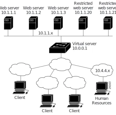
This section provides a configuration example based on the network layout shown inFigure 25. Figure 25 IOS SLB Network Configuration
As shown in the following sample code, the example topology has three public Web servers and two restricted Web servers for privileged clients in subnet 10.4.4.x. The public Web servers are weighted according to their capacity, with server 10.1.1.2 having the lowest capacity and having a connection limit imposed on it. The restricted Web servers are configured as members of the same sticky group, so that HTTP connections and Secure Socket Layer (SSL) connections from the same client use the same real server.
This configuration is coded as follows:
ip slb serverfarm PUBLIC Unrestricted Web server farm
predictor leastconns Use weighted least connections algorithm
real 10.1.1.1 First real server
weight 16 inservice
real 10.1.1.2 Second real server
weight 4
maxconns 1000 Restrict maximum number of connections inservice
real 10.1.1.3 Third real server
weight 24 inservice
ip slb serverfarm RESTRICTED Restricted Web server farm
predictor leastconns Use weighted least connections algorithm
real 10.1.1.20 First real server
in-service
real 10.1.1.21 Second real server
in-service Web server 10.1.1.1 10.4.4.x 10.1.1.x Client Client Client Human Resources Virtual server 10.0.0.1 Web server 10.1.1.2 Web server 10.1.1.3 Restricted web server 10.1.1.21 Restricted web server 10.1.1.20 29163
Configuring Server Load Balancing
Configuration Examples
ip slb vservers PUBLIC_HTTP Unrestricted Web virtual server virtual 10.0.0.1 tcp www Handle HTTP requests
serverfarm PUBLIC Use public Web server farm
inservice
ip slb vservers RESTRICTED_HTTP Restricted HTTP virtual server virtual 10.0.0.1 tcp www Handle HTTP requests
serverfarm RESTRICTED Use restricted Web server farm client 10.4.4.0 255.255.255.0 Only allow clients from 10.4.4.x sticky 60 idle 120 group 1 Couple connections with RESTRICTED_SSL inservice
ip slb vservers RESTRICTED_SSL Restricted SSL virtual server virtual 10.0.0.1 tcp https Handle SSL requests
serverfarm RESTRICTED Use restricted Web server farm client 10.4.4.0 255.255.255.0 Only allow clients from 10.4.4.x
sticky 60 idle 120 group 1 Couple connections with RESTRICTED_HTTP inservice
NAT Configuration Example
This section provides a configuration example based on the network layout shown inFigure 26. Figure 26 IOS SLB NAT Topology
The topology inFigure 26 has four Web servers, configured as follows:
• Servers 1, 2, and 3 are running single HTTP server applications listening on port 80. Server 1 10.1.1.1 Server 2 10.2.1.1 Server 3 10.3.1.1 Server 4 10.4.1.1
Switch A Switch B Switch C
HTTP=80 HTTP=80 HTTP=80 HTTP1 = 8080 HTTP2 = 8081 HTTP3 = 8082
Clients
Configuring Server Load Balancing Configuration Examples
• Server 4 has multiple HTTP server applications listening on ports 8080, 8081, and 8082. Servers 1 and 2 are load balanced using Switch A, which is performing server address translation. Servers 3 and 4 are load balanced using Switches B and C. These two switches are performing server address translation. These switches also perform server port translation for HTTP packets to and from Server 4.
The configuration statements for Switch A are as follows: ip slb serverfarm FARM1
! Translate server addresses nat server ! Server 1 port 80 real 10.1.1.1 inservice ! Server 2 port 80 real 10.2.1.1 inservice ! ip slb vservers HTTP1
! Handle HTTP (port 80) requests virtual 128.1.0.1 tcp www serverfarm FARM1
inservice
The configuration statements for Switch B are as follows: ip slb serverfarm FARM2
! Translate server addresses nat server ! Server 3 port 80 real 10.3.1.1 inservice ! Server 4 port 8080 real 10.4.1.1 port 8080 inservice ! Server 4 port 8081 real 10.4.1.1 port 8081 inservice ! Server 4 port 8082 real 10.4.1.1 port 8082 inservice ! ip slb vservers HTTP2
! Handle HTTP (port 80) requests virtual 128.2.0.1 tcp www serverfarm FARM2
inservice
The configuration statements for Switch C are as follows: ip slb serverfarm FARM2
! Translate server addresses nat server ! Server 3 port 80 real 10.3.1.1 inservice ! Server 4 port 8080 real 10.4.1.1 port 8080 inservice ! Server 4 port 8081 real 10.4.1.1 port 8081 inservice ! Server 4 port 8082
Configuring Server Load Balancing Configuration Examples real 10.4.1.1 port 8082 inservice ! ip slb vservers HTTP2
! Handle HTTP (port 80) requests virtual 128.4.0.1 tcp www serverfarm FARM2
inservice
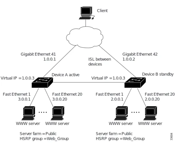
HSRP Configuration Example
Figure 27 shows the topology of an IP network with two Layer 3 switches configured for HSRP. The following conditions exist in this network:
• Device A is the active HSRP Layer 3 switch and handles packets to the real servers with IP addresses 3.0.01 through 3.0.020.
• Device B handles packets to real servers with IP addresses 2.0.0.1 through 2.0.0.20.
• All hosts accessing the network use the IP address of the virtual router (in this case, 1.0.0.3). • The configuration shown uses the Enhanced Interior Gateway Routing Protocol (Enhanced IGRP),
but HSRP can be used with any other routing protocol supported by the Cisco IOS software, such as Open Shortest Path First (OSPF).
Note Some configurations that use HSRP still require a routing protocol for convergence when a topology change occurs. The standby Layer 3 switch becomes active, but connectivity does not occur until convergence occurs.
If the connection between Device A and the client accessing virtual IP 1.0.0.3 fails, fast-converging routing protocols (such as Enhanced IGRP and OSPF) can respond within seconds, ensuring that Device B is prepared to transfer packets that would have gone through Device A.
Configuring Server Load Balancing Configuration Examples
Figure 27 HSRP Example Network Topology
The configuration for Device A is as follows: hostname Device A interface GigabitEthernet 41 ip address 1.0.0.1 255.0.0.0 standby 1 ip 1.0.0.3 standby 1 preempt standby 1 priority 110
standby 1 authentication denmark standby 1 timers 5 15
standby 1 name Web-Group
interface FastEthernet 1 ip address 3.0.0.1 255.0.0.0
router eigrp 1 network 1.0.0.0 network 3.0.0.0
The configuration for Device B is as follows: hostname Device B
interface GigabitEthernet 41 ip address 1.0.0.2 255.0.0.0 standby 1 ip 1.0.0.3
standby 1 preempt
standby 1 authentication denmark
Client Gigabit Ethernet 41 1.0.0.1 Gigabit Ethernet 42 1.0.0.2 Fast Ethernet 1 3.0.0.1 Fast Ethernet 20 3.0.0.20
Device A active Device B standby
Fast Ethernet 20 2.0.0.20 Fast Ethernet 1 2.0.0.1 Virtual IP = 1.0.0.3 ISL between devices Virtual IP = 1.0.0.3
WWW server WWW server WWW server WWW server Server farm = Public
HSRP group = Web_Group
Server farm = Public
Configuring Server Load Balancing
Configuration Examples
standby 1 timers 5 15 standby 1 name Web-Group
interface FastEthernet 41 ip address 2.0.0.1 255.0.0.0
router eigrp 1 network 1.0.0.0 network 2.0.0.0
The standby ip interface configuration command enables HSRP and establishes 1.0.0.3 as the IP address of the virtual router. The configurations of both Layer 3 switches include this command so that both switches share the same virtual IP address. The number 1 establishes Hot Standby group 1. (If you do not specify a group number, the default is group 0.) The configuration for at least one of the Layer 3 switches in the Hot Standby group must specify the IP address of the virtual router; specifying the IP address of the virtual router is optional for other routers in the same Hot Standby group.
The standby preempt interface configuration command allows the Layer 3 switch to become the active switch when its priority is higher than all other HSRP-configured switches in this Hot Standby group. The configurations of both switches include this command so that each can be the standby Layer 3 switch for the other switch. The number 1 indicates that this command applies to Hot Standby group 1. If you do not use the standby preempt command in the configuration for a Layer 3 switch, that switch cannot become the active Layer 3 switch.
The standby priority interface configuration command sets the HSRP priority of the Layer 3 switch to 110, which is higher than the default priority of 100. Only the configuration of Device A includes this command, which makes Device A the default active Layer 3 switch. The number 1 indicates that this command applies to Hot Standby group 1.
The standby authentication interface configuration command establishes an authentication string whose value is an unencrypted eight-character string that is incorporated in each HSRP multicast message. This command is optional. If you choose to use it, each HSRP-configured Layer 3 switch in the group should use the same string so that each switch can authenticate the source of the HSRP messages that it receives. The number 1 indicates that this command applies to Hot Standby group 1. The standby timers interface configuration command sets the interval (in seconds) between hello messages (called the hello time) to 5 seconds, and sets the interval (in seconds) that a Layer 3 switch waits before it declares the active Layer 3 switch to be down (called the hold time) to 8 seconds. (The defaults are 3 and 10 seconds, respectively.) To modify the default values, you must configure each Layer 3 switch to use the same hello time and hold time. The number 1 indicates that this command applies to Hot Standby group 1.
The standby name interface configuration command associates the IOS SLB interface with an HSRP group name (in this case, Web-Group), previously specified on an inservice (virtual server) command. The number 1 indicates that this command applies to Hot Standby group 1.
IOS SLB Stateless Backup Configuration Example
The following commands enable the HSRP standby group 100 IP address, priority, preempt, and timers; and configures a name and authentication for Device A inFigure 27:
standby 100 ip 172.20.100.10 standby 100 priority 110 standby 100 preempt standby 100 timers 5 15 standby 100 name Web_group1 standby 100 authentication Secret
Configuring Server Load Balancing Configuration Examples