Page 243
The 80x86 Instruction Set
Chapter Six
Until now, there has been little discussion of the instructions available on the 80x86 microprocessor. This chapter rectifies this situation. Note that this chapter is mainly for reference. It explains what each instruction does, it does not explain how to combine these instructions to form complete assembly language programs. The rest of this book will explain how to do that.
6.0
Chapter Overview
This chapter discusses the 80x86 real mode instruction set. Like any programming language, there are going to be several instructions you use all the time, some you use occasionally, and some you will rarely, if ever, use. This chapter organizes its presentation by instruction class rather than importance. Since beginning assembly language program-mers do not have to learn the entire instruction set in order to write meaningful assembly language programs, you will probably not have to learn how every instruction operates. The following list describes the instructions this chapter discusses. A “•” symbol marks the important instructions in each group. If you learn only these instructions, you will probably be able to write any assembly language program you want. There are many additional instructions, especially on the 80386 and later processors. These additional instructions make assembly language programming easier, but you do not need to know them to begin writing programs.
80x86 instructions can be (roughly) divided into eight different classes: 1) Data movement instructions
• mov, lea, les , push, pop, pushf, popf
2) Conversions
• cbw, cwd, xlat
3) Arithmetic instructions
• add, inc sub, dec, cmp, neg, mul, imul, div, idiv
4) Logical, shift, rotate, and bit instructions • and, or, xor, not, shl, shr, rcl, rcr
5) I/O instructions
• in, out
6) String instructions • movs, stos, lods
7) Program flow control instructions • jmp, call, ret, conditional jumps 8) Miscellaneous instructions.
• clc, stc, cmc
The following sections describe all the instructions in these groups and how they operate. At one time a text such as this one would recommend against using the extended 80386 instruction set. After all, programs that use such instructions will not run properly on 80286 and earlier processors. Using these additional instructions could limit the num-ber of machines your code would run on. However, the 80386 processor is on the verge of disappearing as this text is being written. You can safely assume that most systems will contain an 80386sx or later processor. This text often uses the 80386 instruction set in vari-ous example programs. Keep in mind, though, that this is only for convenience. There is no program that appears in this text that could not be recoded using only 8088 assembly language instructions.
A word of advice, particularly to those who learn only the instructions noted above: as you read about the 80x86 instruction set you will discover that the individual 80x86 instructions are not very complex and have simple semantics. However, as you approach
Chapter 06
the end of this chapter, you may discover that you haven’t got a clue how to put these sim-ple instructions together to form a comsim-plex program. Fear not, this is a common problem. Later chapters will describe how to form complex programs from these simple instruc-tions.
One quick note: this chapter lists many instructions as “available only on the 80286 and later processors.” In fact, many of these instructions were available on the 80186 microprocessor as well. Since few PC systems employ the 80186 microprocessor, this text ignores that CPU. However, to keep the record straight...
6.1
The Processor Status Register (Flags)
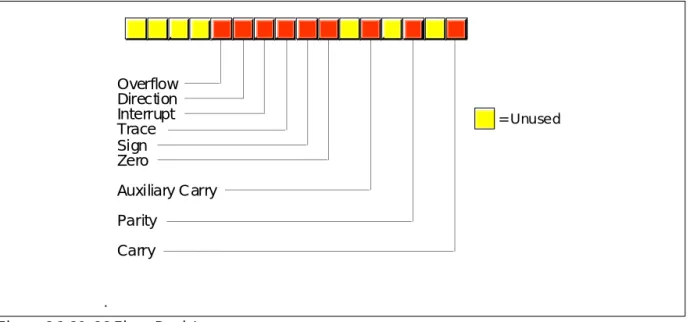
The flags register maintains the current operating mode of the CPU and some instruc-tion state informainstruc-tion. Figure 6.1 shows the layout of the flags register.
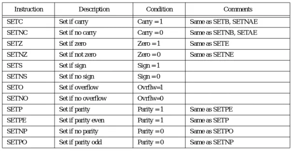
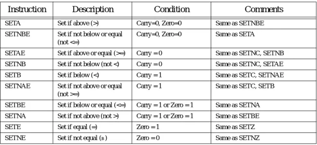
The carry, parity, zero, sign, and overflow flags are special because you can test their status (zero or one) with the setcc and conditional jump instructions (see “The “Set on Condition” Instructions” on page 281 and “The Conditional Jump Instructions” on page 296). The 80x86 uses these bits, the condition codes, to make decisions during program execution.
Various arithmetic, logical, and miscellaneous instructions affect the overflow flag. After an arithmetic operation, this flag contains a one if the result does not fit in the signed destination operand. For example, if you attempt to add the 16 bit signed numbers 7FFFh and 0001h the result is too large so the CPU sets the overflow flag. If the result of the arith-metic operation does not produce a signed overflow, then the CPU clears this flag.
Since the logical operations generally apply to unsigned values, the 80x86 logical instructions simply clear the overflow flag. Other 80x86 instructions leave the overflow flag containing an arbitrary value.
The 80x86 string instructions use the direction flag. When the direction flag is clear, the 80x86 processes string elements from low addresses to high addresses; when set, the CPU processes strings in the opposite direction. See “String Instructions” on page 284 for addi-tional details.
The interrupt enable/disable flag controls the 80x86’s ability to respond to external events known as interrupt requests. Some programs contain certain instruction sequences that the CPU must not interrupt. The interrupt enable/disable flag turns interrupts on or off to guarantee that the CPU does not interrupt those critical sections of code.
Figure 6.1 80x86 Flags Register Overflow Direction Interrupt Trace Sign Zero
Auxiliary Carry Parity
Carry
The 80x86 Instruction Set The trace flag enables or disables the 80x86 trace mode. Debuggers (such as CodeView) use this bit to enable or disable the single step/trace operation. When set, the CPU inter-rupts each instruction and passes control to the debugger software, allowing the debugger to single step through the application. If the trace bit is clear, then the 80x86 executes instructions without the interruption. The 80x86 CPUs do not provide any instructions that directly manipulate this flag. To set or clear the trace flag, you must:
• Push the flags onto the 80x86 stack, • Pop the value into another register, • Tweak the trace flag value,
• Push the result onto the stack, and then • Pop the flags off the stack.
If the result of some computation is negative, the 80x86 sets the sign flag. You can test this flag after an arithmetic operation to check for a negative result. Remember, a value is negative if its H.O. bit is one. Therefore, operations on unsigned values will set the sign flag if the result has a one in the H.O. position.
Various instructions set the zero flag when they generate a zero result. You’ll often use this flag to see if two values are equal (e.g., after subtracting two numbers, they are equal if the result is zero). This flag is also useful after various logical operations to see if a spe-cific bit in a register or memory location contains zero or one.
The auxiliary carry flag supports special binary coded decimal (BCD) operations. Since most programs don’t deal with BCD numbers, you’ll rarely use this flag and even then you’ll not access it directly. The 80x86 CPUs do not provide any instructions that let you directly test, set, or clear this flag. Only the add, adc, sub, sbb, mul, imul, div, idiv, and BCD instructions manipulate this flag.
The parity flag is set according to the parity of the L.O. eight bits of any data operation. If an operation produces an even number of one bits, the CPU sets this flag. It clears this flag if the operation yields an odd number of one bits. This flag is useful in certain data communications programs, however, Intel provided it mainly to provide some compati-bility with the older 8080 µP.
The carry flag has several purposes. First, it denotes an unsigned overflow (much like the overflow flag detects a signed overflow). You will also use it during multiprecision arithmetic and logical operations. Certain bit test, set, clear, and invert instructions on the 80386 directly affect this flag. Finally, since you can easily clear, set, invert, and test it, it is useful for various boolean operations. The carry flag has many purposes and knowing when to use it, and for what purpose, can confuse beginning assembly language program-mers. Fortunately, for any given instruction, the meaning of the carry flag is clear.
The use of these flags will become readily apparent in the coming sections and chap-ters. This section is mainly a formal introduction to the individual flags in the register rather than an attempt to explain the exact function of each flag. For more details on the operation of each flag, keep reading...
6.2
Instruction Encodings
The 80x86 uses a binary encoding for each machine operation. While it is important to have a general understanding of how the 80x86 encodes instructions, it is not important that you memorize the encodings for all the instructions in the instruction set. If you were to write an assembler or disassembler (debugger), you would definitely need to know the exact encodings. For general assembly language programming, however, you won’t need to know the exact encodings.
However, as you become more experienced with assembly language you will proba-bly want to study the encodings of the 80x86 instruction set. Certainly you should be aware of such terms as opcode, mod-reg-r/m byte, displacement value, and so on. Although you do not need to memorize the parameters for each instruction, it is always a good idea to know the lengths and cycle times for instructions you use regularly since this will help
Chapter 06
you write better programs. Chapter Three and Chapter Four provided a detailed look at instruction encodings for various instructions (80x86 and x86); such a discussion was important because you do need to understand how the CPU encodes and executes instructions. This chapter does not deal with such details. This chapter presents a higher level view of each instruction and assumes that you don’t care how the machine treats bits in memory. For those few times that you will need to know the binary encoding for a par-ticular instruction, a complete listing of the instruction encodings appears in Appendix D.
6.3
Data Movement Instructions
The data movement instructions copy values from one location to another. These instructions include mov, xchg, lds, lea, les, lfs, lgs, lss, push, pusha, pushad, pushf, pushfd, pop, popa, popad, popf, popfd, lahf, and sahf.
6.3.1
The MOV Instruction
The mov instruction takes several different forms: mov reg, reg1
mov mem, reg
mov reg, mem
mov mem, immediate data mov reg, immediate data mov ax/al, mem
mov mem, ax/al mov segreg, mem16 mov segreg, reg16 mov mem16, segreg
mov reg16, segreg
The last chapter discussed the mov instruction in detail, only a few minor comments are worthwhile here. First, there are variations of the mov instruction that are faster and shorter than other mov instructions that do the same job. For example, both the
mov ax, mem and mov reg, mem instructions can load the ax register from a memory loca-tion. On all processors the first version is shorter. On the earlier members of the 80x86 family, it is faster as well.
There are two very important details to note about the mov instruction. First, there is no memory to memory move operation. The mod-reg-r/m addressing mode byte (see Chapter Four) allows two register operands or a single register and a single memory oper-and. There is no form of the mov instruction that allows you to encode two memory addresses into the same instruction. Second, you cannot move immediate data into a seg-ment register. The only instructions that move data into or out of a segseg-ment register have mod-reg-r/m bytes associated with them; there is no format that moves an immediate value into a segment register. Two common errors beginning programmers make are attempting a memory to memory move and trying to load a segment register with a con-stant.
The operands to the mov instruction may be bytes, words, or double words2. Both operands must be the same size or MASM will generate an error while assembling your program. This applies to memory operands and register operands. If you declare a vari-able, B, using byte and attempt to load this variable into the ax register, MASM will com-plain about a type conflict.
The CPU extends immediate data to the size of the destination operand (unless it is too big to fit in the destination operand, which is an error). Note that you can move an
1. This chapter uses “reg”, by itself, to denote any eight bit, sixteen bit, or (on the 80386 and later) 32 bit general purpose CPU register (AL/AX/EAX, BL/BX/EBX, SI/ESI, etc.)
The 80x86 Instruction Set immediate value into a memory location. The same rules concerning size apply. However, MASM cannot determine the size of certain memory operands. For example, does the instruction mov [bx], 0 store an eight bit, sixteen bit, or thirty-two bit value? MASM can-not tell, so it reports an error. This problem does not exist when you move an immediate value into a variable you’ve declared in your program. For example, if you’ve declared B
as a byte variable, MASM knows to store an eight bit zero into B for the instruction
mov B, 0. Only those memory operands involving pointers with no variable operands suf-fer from this problem. The solution is to explicitly tell MASM whether the operand is a byte, word, or double word. You can accomplish this with the following instruction forms:
mov byte ptr [bx], 0 mov word ptr [bx], 0
mov dword ptr [bx], 0 (3)
(3) Available only on 80386 and later processors
For more details on the type ptr operator, see Chapter Eight.
Moves to and from segment registers are always 16 bits; the mod-reg-r/m operand must be 16 bits or MASM will generate an error. Since you cannot load a constant directly into a segment register, a common solution is to load the constant into an 80x86 general purpose register and then copy it to the segment register. For example, the following two instruction sequence loads the es register with the value 40h:
mov ax, 40h
mov es, ax
Note that almost any general purpose register would suffice. Here, ax was chosen arbi-trarily.
The mov instructions do not affect any flags. In particular, the 80x86 preserves the flag values across the execution of a mov instruction.
6.3.2
The XCHG Instruction
The xchg (exchange) instruction swaps two values. The general form is xchg operand1, operand2
There are four specific forms of this instruction on the 80x86: xchg reg, mem
xchg reg, reg xchg ax, reg16
xchg eax, reg32 (3) (3) Available only on 80386 and later processors
The first two general forms require two or more bytes for the opcode and mod-reg-r/m bytes (a displacement, if necessary, requires additional bytes). The third and fourth forms are special forms of the second that exchange data in the (e)ax register with another 16 or 32 bit register. The 16 bit form uses a single byte opcode that is shorter than the other two forms that use a one byte opcode and a mod-reg-r/m byte.
Already you should note a pattern developing: the 80x86 family often provides shorter and faster versions of instructions that use the ax register. Therefore, you should try to arrange your computations so that they use the (e)ax register as much as possible. The xchg instruction is a perfect example, the form that exchanges 16 bit registers is only one byte long.
Note that the order of the xchg’s operands does not matter. That is, you could enter
xchg mem, reg and get the same result as xchg reg, mem. Most modern assemblers will automatically emit the opcode for the shorter xchg ax, reg instruction if you specify
Chapter 06
Both operands must be the same size. On pre-80386 processors the operands may be eight or sixteen bits. On 80386 and later processors the operands may be 32 bits long as well.
The xchg instruction does not modify any flags.
6.3.3
The LDS, LES, LFS, LGS, and LSS Instructions
The lds, les, lfs, lgs, and lss instructions let you load a 16 bit general purpose register and segment register pair with a single instruction. On the 80286 and earlier, the lds and
les instructions are the only instructions that directly process values larger than 32 bits. The general form is
LxS dest, source These instructions take the specific forms:
lds reg16, mem32 les reg16, mem32
lfs reg16, mem32 (3)
lgs reg16, mem32 (3)
lss reg16, mem32 (3)
(3) Available only on 80386 and later processors
Reg16 is any general purpose 16 bit register and mem32 is a double word memory location (declared with the dword statement).
These instructions will load the 32 bit double word at the address specified by mem32
into reg16 and the ds, es, fs, gs, or ss registers. They load the general purpose register from the L.O. word of the memory operand and the segment register from the H.O. word. The following algorithms describe the exact operation:
lds reg16, mem32:
reg16 := [mem32] ds := [mem32 + 2] les reg16, mem32:
reg16 := [mem32] es := [mem32 + 2] lfs reg16, mem32:
reg16 := [mem32] fs := [mem32 + 2] lgs reg16, mem32:
reg16 := [mem32] gs := [mem32 + 2] lss reg16, mem32:
reg16 := [mem32] ss := [mem32 + 2]
Since the LxS instructions load the 80x86’s segment registers, you must not use these instructions for arbitrary purposes. Use them to set up (far) pointers to certain data objects as discussed in Chapter Four. Any other use may cause problems with your code if you attempt to port it to Windows, OS/2 or UNIX.
Keep in mind that these instructions load the four bytes at a given memory location into the register pair; they do not load the address of a variable into the register pair (i.e., this instruction does not have an immediate mode). To learn how to load the address of a variable into a register pair, see Chapter Eight.
The LxS instructions do not affect any of the 80x86’s flag bits.
6.3.4
The LEA Instruction
The lea (Load Effective Address) instruction is another instruction used to prepare pointer values. The lea instruction takes the form:
lea dest, source The specific forms on the 80x86 are
lea reg16, mem
lea reg32, mem (3)
(3) Available only on 80386 and later processors.
It loads the specified 16 or 32 bit general purpose register with the effective address of the specified memory location. The effective address is the final memory address obtained after all addressing mode computations. For example, lea ax, ds:[1234h] loads the ax reg-ister with the address of memory location 1234h; here it just loads the ax register with the value 1234h. If you think about it for a moment, this isn’t a very exciting operation. After all, the mov ax, immediate_data instruction can do this. So why bother with the lea instruc-tion at all? Well, there are many other forms of a memory operand besides displace-ment-only operands. Consider the following lea instructions:
lea ax, [bx]
lea bx, 3[bx]
lea ax, 3[bx]
lea bx, 4[bp+si]
lea ax, -123[di]
The lea ax, [bx] instruction copies the address of the expression [bx] into the ax regis-ter. Since the effective address is the value in the bx register, this instruction copies bx’s value into the ax register. Again, this instruction isn’t very interesting because mov can do the same thing, even faster.
The lea bx,3[bx] instruction copies the effective address of 3[bx] into the bx register. Since this effective address is equal to the current value of bx plus three, this lea instruction effectively adds three to the bx register. There is an add instruction that will let you add three to the bx register, so again, the lea instruction is superfluous for this purpose.
The third lea instruction above shows where lea really begins to shine. lea ax, 3[bx]
copies the address of the memory location 3[bx] into the ax register; i.e., it adds three with the value in the bx register and moves the sum into ax. This is an excellent example of how you can use the lea instruction to do a mov operation and an addition with a single instruc-tion.
The final two instructions above, lea bx,4[bp+si] and lea ax,-123[di] provide additional examples of lea instructions that are more efficient than their mov/add counterparts.
On the 80386 and later processors, you can use the scaled indexed addressing modes to multiply by two, four, or eight as well as add registers and displacements together. Intel strongly suggests the use of the lea instruction since it is much faster than a sequence of instructions computing the same result.
The (real) purpose of lea is to load a register with a memory address. For example,
lea bx, 128[bp+di] sets up bx with the address of the byte referenced by 128[BP+DI]. As it turns out, an instruction of the form mov al,[bx] runs faster than an instruction of the form mov al,128[bp+di]. If this instruction executes several times, it is probably more effi-cient to load the effective address of 128[bp+di] into the bx register and use the [bx] address-ing mode. This is a common optimization in high performance programs.
The lea instruction does not affect any of the 80x86’s flag bits.
6.3.5
The PUSH and POP Instructions
The 80x86 push and pop instructions manipulate data on the 80x86’s hardware stack. There are 19 varieties of the push and pop instructions3, they are
push reg16 pop reg16
push reg32 (3)
pop reg32 (3)
push segreg
pop segreg (except CS)
push memory
pop memory
push immediate_data (2)
pusha (2)
popa (2)
pushad (3)
popad (3)
pushf popf
pushfd (3)
popfd (3)
enter imm, imm (2)
leave (2)
(2)- Available only on 80286 and later processors. (3)- Available only on 80386 and later processors.
The first two instructions push and pop a 16 bit general purpose register. This is a compact (one byte) version designed specifically for registers. Note that there is a second form that provides a mod-reg-r/m byte that could push registers as well; most assemblers only use that form for pushing the value of a memory location.
The second pair of instructions push or pop an 80386 32 bit general purpose register. This is really nothing more than the push register instruction described in the previous paragraph with a size prefix byte.
The third pair of push/pop instructions let you push or pop an 80x86 segment register. Note that the instructions that push fs and gs are longer than those that push cs, ds, es, and
ss, see Appendix D for the exact details. You can only push the cs register (popping the cs
register would create some interesting program flow control problems).
The fourth pair of push/pop instructions allow you to push or pop the contents of a memory location. On the 80286 and earlier, this must be a 16 bit value. For memory opera-tions without an explicit type (e.g., [bx]) you must either use the pushw mnemonic or explicitly state the size using an instruction like push word ptr [bx]. On the 80386 and later you can push and pop 16 or 32 bit values4. You can use dword memory operands, you can use the pushd mnemonic, or you can use the dword ptr operator to force 32 bit operation. Examples:
push DblWordVar push dword ptr [bx] pushd dword
The pusha and popa instructions (available on the 80286 and later) push and pop all the 80x86 16 bit general purpose registers. Pusha pushes the registers in the following order:
ax, cx, dx, bx, sp, bp, si, and then di. Popa pops these registers in the reverse order. Pushad
and Popad (available on the 80386 and later) do the same thing on the 80386’s 32 bit regis-ter set. Note that these “push all” and “pop all” instructions do not push or pop the flags or segment registers.
The pushf and popf instructions allow you to push/pop the processor status register (the flags). Note that these two instructions provide a mechanism to modify the 80x86’s trace flag. See the description of this process earlier in this chapter. Of course, you can set and clear the other flags in this fashion as well. However, most of the other flags you’ll want to modify (specifically, the condition codes) provide specific instructions or other simple sequences for this purpose.
Enter and leave push/pop the bp register and allocate storage for local variables on the stack. You will see more on these instructions in a later chapter. This chapter does not
sider them since they are not particularly useful outside the context of procedure entry and exit.
“So what do these instructions do?” you’re probably asking by now. The push instruc-tions move data onto the 80x86 hardware stack and the pop instructions move data from the stack to memory or to a register. The following is an algorithmic description of each instruction:
push instructions (16 bits): SP := SP - 2
[SS:SP] := 16 bit operand (store result at location SS:SP.)
pop instructions (16 bits): 16-bit operand := [SS:SP] SP := SP + 2
push instructions (32 bits): SP := SP - 4
[SS:SP] := 32 bit operand
pop instructions (32 bits): 32 bit operand := [SS:SP] SP := SP + 4
You can treat the pusha/pushad and popa/popad instructions as equivalent to the corre-sponding sequence of 16 or 32 bit push/pop operations (e.g., push ax, push cx, push dx, push bx, etc.).
Notice three things about the 80x86 hardware stack. First, it is always in the stack seg-ment (wherever ss points). Second, the stack grows down in memory. That is, as you push values onto the stack the CPU stores them into successively lower memory locations. Finally, the 80x86 hardware stack pointer (ss:sp) always contains the address of the value on the top of the stack (the last value pushed on the stack).
You can use the 80x86 hardware stack for temporarily saving registers and variables, passing parameters to a procedure, allocating storage for local variables, and other uses. The push and pop instructions are extremely valuable for manipulating these items on the stack. You’ll get a chance to see how to use them later in this text.
Most of the push and pop instructions do not affect any of the flags in the 80x86 proces-sor status register. The popf/popfd instructions, by their very nature, can modify all the flag bits in the 80x86 processor status register (flags register). Pushf and pushfd push the flags onto the stack, but they do not change any flags while doing so.
All pushes and pops are 16 or 32 bit operations. There is no (easy) way to push a sin-gle eight bit value onto the stack. To push an eight bit value you would need to load it into the H.O. byte of a 16 bit register, push that register, and then add one to the stack pointer. On all processors except the 8088, this would slow future stack access since sp now con-tains an odd address, misaligning any further pushes and pops. Therefore, most programs push or pop 16 bits, even when dealing with eight bit values.
Although it is relatively safe to push an eight bit memory variable, be careful when popping the stack to an eight bit memory location. Pushing an eight bit variable with
push word ptr ByteVar pushes two bytes, the byte in the variable ByteVar and the byte immediately following it. Your code can simply ignore the extra byte this instruction pushes onto the stack. Popping such values is not quite so straight forward. Generally, it doesn’t hurt if you push these two bytes. However, it can be a disaster if you pop a value and wipe out the following byte in memory. There are only two solutions to this problem. First, you could pop the 16 bit value into a register like ax and then store the L.O. byte of that register into the byte variable. The second solution is to reserve an extra byte of pad-ding after the byte variable to hold the whole word you will pop. Most programs use the former approach.
6.3.6
The LAHF and SAHF Instructions
The lahf (load ah from flags) and sahf (store ah into flags) instructions are archaic instructions included in the 80x86’s instruction set to help improve compatibility with Intel’s older 8080 µP chip. As such, these instructions have very little use in modern day 80x86 programs. The lahf instruction does not affect any of the flag bits. The sahf instruc-tion, by its very nature, modifies the S, Z, A, P, and C bits in the processor status register. These instructions do not require any operands and you use them in the following man-ner:
sahf lahf
Sahf only affects the L.O. eight bits of the flags register. Likewise, lahf only loads the L.O. eight bits of the flags register into the AH register. These instructions do not deal with the overflow, direction, interrupt disable, or trace flags. The fact that these instructions do not deal with the overflow flag is an important limitation.
Sahf has one major use. When using a floating point processor (8087, 80287, 80387, 80486, Pentium, etc.) you can use the sahf instruction to copy the floating point status reg-ister flags into the 80x86’s flag regreg-ister. You’ll see this use in the chapter on floating point arithmetic (see “Floating Point Arithmetic” on page 771).
6.4
Conversions
The 80x86 instruction set provides several conversion instructions. They include
movzx, movsx, cbw, cwd, cwde, cdq, bswap, and xlat. Most of these instructions sign or zero extend values, the last two convert between storage formats and translate values via a lookup table. These instructions take the general form:
movzx dest, src ;Dest must be twice the size of src. movsx dest, src ;Dest must be twice the size of src. cbw
cwd cwde cdq
bswap reg32
xlat ;Special form allows an operand.
6.4.1
The MOVZX, MOVSX, CBW, CWD, CWDE, and CDQ Instructions
These instructions zero and sign extend values. The cbw and cwd instructions are available on all 80x86 processors. The movzx, movsx, cwde, and cdq instructions are avail-able only on 80386 and later processors.
The cbw (convert byte to word) instruction sign extends the eight bit value in al to ax. That is, it copies bit seven of AL throughout bits 8-15 of ax. This instruction is especially important before executing an eight bit division (as you’ll see in the section “Arithmetic Instructions” on page 255). This instruction requires no operands and you use it as fol-lows:
cbw
The cwd (convert word to double word) instruction sign extends the 16 bit value in ax
to 32 bits and places the result in dx:ax. It copies bit 15 of ax throughout the bits in dx. It is available on all 80x86 processors which explains why it doesn’t sign extend the value into
eax. Like the cbw instruction, this instruction is very important for division operations.
Cwd requires no operands and you use it as follows cwd
The cwde instruction sign extends the 16 bit value in ax to 32 bits and places the result in eax by copying bit 15 of ax throughout bits 16..31 of eax. This instruction is available only on the 80386 and later processors. As with cbw and cwd the instruction has no oper-ands and you use it as follows:
cwde
The cdq instruction sign extends the 32 bit value in eax to 64 bits and places the result in edx:eax by copying bit 31 of eax throughout bits 0..31 of edx. This instruction is available only on the 80386 and later. You would normally use this instruction before a long divi-sion operation. As with cbw, cwd, and cwde the instruction has no operands and you use it as follows:
cdq
If you want to sign extend an eight bit value to 32 or 64 bits using these instructions, you could use sequences like the following:
; Sign extend al to dx:ax cbw cwd ; Sign extend al to eax
cbw cwde ; Sign extend al to edx:eax
cbw cwde cdq
You can also use the movsx for sign extensions from eight to sixteen or thirty-two bits. The movsx instruction is a generalized form of the cbw, cwd, and cwde instructions. It will sign extend an eight bit value to a sixteen or thirty-two bits, or sign extend a sixteen bit value to a thirty-two bits. This instruction uses a mod-reg-r/m byte to specify the two operands. The allowable forms for this instruction are
movsx reg16, mem8 movsx reg16, reg8 movsx reg32, mem8
movsx reg32, reg8 movsx reg32, mem16 movsx reg32, reg16
Note that anything you can do with the cbw and cwde instructions, you can do with a
movsx instruction:
movsx ax, al ;CBW
movsx eax, ax ;CWDE
movsx eax, al ;CBW followed by CWDE
However, the cbw and cwde instructions are shorter and sometimes faster. This instruction is available only on the 80386 and later processors. Note that there are not direct movsx
equivalents for the cwd and cdq instructions.
The movzx instruction works just like the movsx instruction, except it extends unsigned values via zero extension rather than signed values through sign extension. The syntax is the same as for the movsx instructions except, of course, you use the movzx mnemonic rather than movsx.
Note that if you want to zero extend an eight bit register to 16 bits (e.g., al to ax) a sim-ple mov instruction is faster and shorter than movzx. For example,
mov bh, 0
is faster and shorter than
movzx bx, bl
Of course, if you move the data to a different 16 bit register (e.g., movzx bx, al) the movzx
Like the movsx instruction, the movzx instruction is available only on 80386 and later processors. The sign and zero extension instructions do not affect any flags.
6.4.2
The BSWAP Instruction
The bswap instruction, available only on 80486 (yes, 486) and later processors, con-verts between 32 bit little endian and big endian values. This instruction accepts only a sin-gle 32 bit register operand. It swaps the first byte with the fourth and the second byte with the third. The syntax for the instruction is
bswap reg32
where reg32 is an 80486 32 bit general purpose register.
The Intel processor families use a memory organization known as little endian byte organization. In little endian byte organization, the L.O. byte of a multi-byte sequence appears at the lowest address in memory. For example, bits zero through seven of a 32 bit value appear at the lowest address; bits eight through fifteen appear at the second address in memory; bits 16 through 23 appear in the third byte, and bits 24 through 31 appear in the fourth byte.
Another popular memory organization is big endian. In the big endian scheme, bits twenty-four through thirty-one appear in the first (lowest) address, bits sixteen through twenty-three appear in the second byte, bits eight through fifteen appear in the third byte, and bits zero through seven appear in the fourth byte. CPUs such as the Motorola 68000 family used by Apple in their Macintosh computer and many RISC chips employ the big endian scheme.
Normally, you wouldn’t care about byte organization in memory since programs written for an Intel processor in assembly language do not run on a 68000 processor. How-ever, it is very common to exchange data between machines with different byte organiza-tions. Unfortunately, 16 and 32 bit values on big endian machines do not produce correct results when you use them on little endian machines. This is where the bswap instruction comes in. It lets you easily convert 32 bit big endian values to 32 bit little endian values.
One interesting use of the bswap instruction is to provide access to a second set of 16 bit general purpose registers. If you are using only 16 bit registers in your code, you can double the number of available registers by using the bswap instruction to exchange the data in a 16 bit register with the H.O. word of a thirty-two bit register. For example, you can keep two 16 bit values in eax and move the appropriate value into ax as follows:
< Some computations that leave a result in AX > bswap eax
< Some additional computations involving AX > bswap eax
< Some computations involving the original value in AX > bswap eax
< Computations involving the 2nd copy of AX from above >
You can use this technique on the 80486 to obtain two copies of ax, bx, cx, dx, si, di, and
bp. You must exercise extreme caution if you use this technique with the sp register. Note: to convert 16 bit big endian values to 16 bit little endian values just use the 80x86 xchg instruction. For example, if ax contains a 16 bit big endian value, you can con-vert it to a 16 bit little endian value (or vice versa) using:
xchg al, ah
6.4.3
The XLAT Instruction
The xlat instruction translates the value in the al register based on a lookup table in memory. It does the following:
temp := al+bx al := ds:[temp]
that is, bx points at a table in the current data segment. Xlat replaces the value in al with the byte at the offset originally in al. If al contains four, xlat replaces the value in al with the fifth item (offset four) within the table pointed at by ds:bx. The xlat instruction takes the form:
xlat
Typically it has no operand. You can specify one but the assembler virtually ignores it. The only purpose for specifying an operand is so you can provide a segment override pre-fix:
xlat es:Table
This tells the assembler to emit an es: segment prefix byte before the instruction. You must still load bx with the address of Table; the form above does not provide the address of
Table to the instruction. Only the segment override prefix in the operand is significant. The xlat instruction does not affect the 80x86’s flags register.
6.5
Arithmetic Instructions
The 80x86 provides many arithmetic operations: addition, subtraction, negation, mul-tiplication, division/modulo (remainder), and comparing two values. The instructions that handle these operations are add, adc, sub, sbb, mul, imul, div, idiv, cmp, neg, inc, dec, xadd, cmpxchg, and some miscellaneous conversion instructions: aaa, aad, aam, aas, daa, and das. The following sections describe these instructions in detail.
The generic forms for these instructions are
add dest, src dest := dest + src
adc dest, src dest := dest + src + C
SUB dest, src dest := dest - src
sbb dest, src dest := dest - src - C
mul src acc := acc * src
imul src acc := acc * src
imul dest, src1, imm_src dest := src1 * imm_src imul dest, imm_src dest := dest * imm_src
imul dest, src dest := dest * src
div src acc := xacc /-mod src
idiv src acc := xacc /-mod src
cmp dest, src dest - src (and set flags)
neg dest dest := - dest
inc dest dest := dest + 1
dec dest dest := dest - 1
xadd dest, src (see text)
cmpxchg operand1, operand2 (see text) cmpxchg8ax, operand (see text)
aaa (see text)
aad (see text)
aam (see text)
aas (see text)
daa (see text)
6.5.1
The Addition Instructions: ADD, ADC, INC, XADD, AAA, and DAA
These instructions take the forms:add reg, reg
add reg, mem
add mem, reg
add reg, immediate data add mem, immediate data add eax/ax/al, immediate data
adc forms are identical to ADD.
inc reg
inc mem
inc reg16 xadd mem, reg xadd reg, reg aaa
daa
Note that the aaa and daa instructions use the implied addressing mode and allow no operands.
6.5.1.1
The ADD and ADC Instructions
The syntax of add and adc (add with carry) is similar to mov. Like mov, there are special forms for the ax/eax register that are more efficient. Unlike mov, you cannot add a value to a segment register with these instructions.
The add instruction adds the contents of the source operand to the destination oper-and. For example, addax, bx adds bx to ax leaving the sum in the ax register. Add com-putes dest :=dest+source while adc computes dest :=dest+source+C where C represents the value in the carry flag. Therefore, if the carry flag is clear before execution, adc behaves exactly like the add instruction.
Both instructions affect the flags identically. They set the flags as follows: • The overflow flag denotes a signed arithmetic overflow.
• The carry flag denotes an unsigned arithmetic overflow.
• The sign flag denotes a negative result (i.e., the H.O. bit of the result is one).
• The zero flag is set if the result of the addition is zero.
• The auxiliary carry flag contains one if a BCD overflow out of the L.O. nibble occurs.
• The parity flag is set or cleared depending on the parity of the L.O. eight bits of the result. If there are an even number of one bits in the result, the ADD instructions will set the parity flag to one (to denote even parity). If there are an odd number of one bits in the result, the ADD instructions clear the parity flag (to denote odd parity).
The add and adc instructions do not affect any other flags.
The add and adc instructions allow eight, sixteen, and (on the 80386 and later) thirty-two bit operands. Both source and destination operands must be the same size. See Chapter Nine if you want to add operands whose size is different.
Since there are no memory to memory additions, you must load memory operands into registers if you want to add two variables together. The following code examples demonstrate possible forms for the add instruction:
; J:= K + M
mov ax, K
add ax, M
If you want to add several values together, you can easily compute the sum in a single register:
; J := K + M + N + P
mov ax, K
add ax, M
add ax, N
add ax, P
mov J, ax
If you want to reduce the number of hazards on an 80486 or Pentium processor, you can use code like the following:
mov bx, K
mov ax, M
add bx, N
add ax, P
add ax, bx
mov J, ax
One thing that beginning assembly language programmers often forget is that you can add a register to a memory location. Sometimes beginning programmers even believe that both operands have to be in registers, completely forgetting the lessons from Chapter Four. The 80x86 is a CISC processor that allows you to use memory addressing modes with various instructions like add. It is often more efficient to take advantages of the 80x86’s memory addressing capabilities
; J := K + J
mov ax, K ;This works because addition is
add J, ax ; commutative!
; Often, beginners will code the above as one of the following two sequences. ; This is unnecessary!
mov ax, J ;Really BAD way to compute
mov bx, K ; J := J + K.
add ax, bx
mov J, ax
mov ax, J ;Better, but still not a good way to
add ax, K ; compute J := J + K
mov J, ax
Of course, if you want to add a constant to a memory location, you only need a single instruction. The 80x86 lets you directly add a constant to memory:
; J := J + 2
add J, 2
There are special forms of the add and adc instructions that add an immediate constant to the al, ax, or eax register. These forms are shorter than the standard add reg, immediate
instruction. Other instructions also provide shorter forms when using these registers; therefore, you should try to keep computations in the accumulator registers (al, ax, and eax) as much as possible.
add bl, 2 ;Three bytes long
add al, 2 ;Two bytes long
add bx, 2 ;Four bytes long
add ax, 2 ;Three bytes long
etc.
Another optimization concerns the use of small signed constants with the add and adc
instructions. If a value is in the range -128,,+127, the add and adc instructions will sign extend an eight bit immediate constant to the necessary destination size (eight, sixteen, or thirty-two bits). Therefore, you should try to use small constants, if possible, with the add
6.5.1.2
The INC Instruction
The inc (increment) instruction adds one to its operand. Except for the carry flag, inc
sets the flags the same way as add operand, 1 would.
Note that there are two forms of inc for 16 or 32 bit registers. They are the inc reg and
inc reg16 instructions. The inc reg and inc mem instructions are the same. This instruction consists of an opcode byte followed by a mod-reg-r/m byte (see Appendix D for details). The inc reg16 instruction has a single byte opcode. Therefore, it is shorter and usually faster.
The inc operand may be an eight bit, sixteen bit, or (on the 80386 and later) thirty-two bit register or memory location.
The inc instruction is more compact and often faster than the comparable add reg, 1 or
add mem, 1 instruction. Indeed, the inc reg16 instruction is one byte long, so it turns out that two such instructions are shorter than the comparable add reg, 1 instruction; however, the two increment instructions will run slower on most modern members of the 80x86 family. The inc instruction is very important because adding one to a register is a very mon operation. Incrementing loop control variables or indices into an array is a very com-mon operation, perfect for the inc instruction. The fact that inc does not affect the carry flag is very important. This allows you to increment array indices without affecting the result of a multiprecision arithmetic operation ( see “Arithmetic and Logical Operations” on page 459 for more details about multiprecision arithmetic).
6.5.1.3
The XADD Instruction
Xadd (Exchange and Add) is another 80486 (and later) instruction. It does not appear on the 80386 and earlier processors. This instruction adds the source operand to the desti-nation operand and stores the sum in the destidesti-nation operand. However, just before stor-ing the sum, it copies the original value of the destination operand into the source operand. The following algorithm describes this operation:
xadd dest, source temp := dest
dest := dest + source source := temp
The xadd sets the flags just as the add instruction would. The xadd instruction allows eight, sixteen, and thirty-two bit operands. Both source and destination operands must be the same size.
6.5.1.4
The AAA and DAA Instructions
The aaa (ASCII adjust after addition) and daa (decimal adjust for addition) instruc-tions support BCD arithmetic. Beyond this chapter, this text will not cover BCD or ASCII arithmetic since it is mainly for controller applications, not general purpose programming applications. BCD values are decimal integer coded in binary form with one decimal digit (0..9) per nibble. ASCII (numeric) values contain a single decimal digit per byte, the H.O. nibble of the byte should contain zero.
The aaa and daa instructions modify the result of a binary addition to correct it for ASCII or decimal arithmetic. For example, to add two BCD values, you would add them as though they were binary numbers and then execute the daa instruction afterwards to correct the results. Likewise, you can use the aaa instruction to adjust the result of an ASCII addition after executing an add instruction. Please note that these two instructions assume that the add operands were proper decimal or ASCII values. If you add binary
(non-decimal or non-ASCII) values together and try to adjust them with these instruc-tions, you will not produce correct results.
The choice of the name “ASCII arithmetic” is unfortunate, since these values are not true ASCII characters. A name like “unpacked BCD” would be more appropriate. ever, Intel uses the name ASCII, so this text will do so as well to avoid confusion. How-ever, you will often hear the term “unpacked BCD” to describe this data type.
Aaa (which you generally execute after an add, adc, or xadd instruction) checks the value in al for BCD overflow. It works according to the following basic algorithm:
if ( (al and 0Fh) > 9 or (AuxC5 =1) ) then if (8088 or 8086)6 then
al := al + 6 else
ax := ax + 6 endif
ah := ah + 1
AuxC := 1 ;Set auxilliary carry
Carry := 1 ; and carry flags.
else
AuxC := 0 ;Clear auxilliary carry
Carry := 0 ; and carry flags.
endif
al := al and 0Fh
The aaa instruction is mainly useful for adding strings of digits where there is exactly one decimal digit per byte in a string of numbers. This text will not deal with BCD or ASCII numeric strings, so you can safely ignore this instruction for now. Of course, you can use the aaa instruction any time you need to use the algorithm above, but that would probably be a rare situation.
The daa instruction functions like aaa except it handles packed BCD (binary code dec-imal) values rather than the one digit per byte unpacked values aaa handles. As for aaa,
daa’s main purpose is to add strings of BCD digits (with two digits per byte). The algo-rithm for daa is
if ( (AL and 0Fh) > 9 or (AuxC = 1)) then al := al + 6
AuxC := 1 ;Set Auxilliary carry.
endif
if ( (al > 9Fh) or (Carry = 1)) then al := al + 60h
Carry := 1; ;Set carry flag.
endif
6.5.2
The Subtraction Instructions: SUB, SBB, DEC, AAS, and DAS
The sub (subtract), sbb (subtract with borrow), dec (decrement), aas (ASCII adjust for subtraction), and das (decimal adjust for subtraction) instructions work as you expect. Their syntax is very similar to that of the add instructions:
sub reg, reg
sub reg, mem
sub mem, reg
sub reg, immediate data sub mem, immediate data sub eax/ax/al, immediate data
5. AuxC denotes the auxiliary carry flag in the flags register.
6. The 8086/8088 work differently from the later processors, but for all valid operands all 80x86 processors pro-duce correct results.
sbb forms are identical to sub.
dec reg
dec mem
dec reg16 aas
das
The sub instruction computes the value dest := dest - src. The sbb instruction computes
dest := dest - src - C. Note that subtraction is not commutative. If you want to compute the result for dest := src - dest you will need to use several instructions, assuming you need to preserve the source operand).
One last subject worth discussing is how the sub instruction affects the 80x86 flags reg-ister7. The sub, sbb, and dec instructions affect the flags as follows:
• They set the zero flag if the result is zero. This occurs only if the operands are equal for sub and sbb. The dec instruction sets the zero flag only when it decrements the value one.
• These instructions set the sign flag if the result is negative.
• These instructions set the overflow flag if signed overflow/underflow occurs.
• They set the auxiliary carry flag as necessary for BCD/ASCII arithmetic. • They set the parity flag according to the number of one bits appearing in
the result value.
• The sub and sbb instructions set the carry flag if an unsigned overflow occurs. Note that the dec instruction does not affect the carry flag.
The aas instruction, like its aaa counterpart, lets you operate on strings of ASCII num-bers with one decimal digit (in the range 0..9) per byte. You would use this instruction after a sub or sbb instruction on the ASCII value. This instruction uses the following algo-rithm:
if ( (al and 0Fh) > 9 or AuxC = 1) then al := al - 6
ah := ah - 1
AuxC := 1 ;Set auxilliary carry
Carry := 1 ; and carry flags. else
AuxC := 0 ;Clear Auxilliary carry Carry := 0 ; and carry flags. endif
al := al and 0Fh
The das instruction handles the same operation for BCD values, it uses the following algorithm:
if ( (al and 0Fh) > 9 or (AuxC = 1)) then al := al -6
AuxC = 1 endif
if (al > 9Fh or Carry = 1) then al := al - 60h
Carry := 1 ;Set the Carry flag. endif
Since subtraction is not commutative, you cannot use the sub instruction as freely as the add instruction. The following examples demonstrate some of the problems you may encounter.
; J := K - J
mov ax, K ;This is a nice try, but it computes sub J, ax ; J := J - K, subtraction isn’t
; commutative!
mov ax, K ;Correct solution.
sub ax, J
mov J, ax
; J := J - (K + M) -- Don’t forget this is equivalent to J := J - K - M
mov ax, K ;Computes AX := K + M
add ax, M
sub J, ax ;Computes J := J - (K + M) mov ax, J ;Another solution, though less
sub ax, K ;Efficient
sub ax, M
mov J, ax
Note that the sub and sbb instructions, like add and adc, provide short forms to sub-tract a constant from an accumulator register (al, ax, or eax). For this reason, you should try to keep arithmetic operations in the accumulator registers as much as possible. The sub
and sbb instructions also provide a shorter form when subtracting constants in the range -128..+127 from a memory location or register. The instruction will automatically sign extend an eight bit signed value to the necessary size before the subtraction occurs. See Appendix D for the details.
In practice, there really isn’t a need for an instruction that subtracts a constant from a register or memory location – adding a negative value achieves the same result. Neverthe-less, Intel provides a subtract immediate instruction.
After the execution of a sub instruction, the condition code bits (carry, sign, overflow, and zero) in the flags register contain values you can test to see if one of sub’s operands is equal, not equal, less than, less than or equal, greater than, or greater than or equal to the other operand. See the cmp instruction for more details.
6.5.3
The CMP Instruction
The cmp (compare) instruction is identical to the sub instruction with one crucial dif-ference – it does not store the difdif-ference back into the destination operand. The syntax for the cmp instruction is very similar to sub, the generic form is
cmp dest, src The specific forms are
cmp reg, reg
cmp reg, mem
cmp mem, reg
cmp reg, immediate data cmp mem, immediate data cmp eax/ax/al, immediate data
The cmp instruction updates the 80x86’s flags according to the result of the subtraction operation (dest - src). You can test the result of the comparison by checking the appropri-ate flags in the flags register. For details on how this is done, see “The “Set on Condition” Instructions” on page 281 and “The Conditional Jump Instructions” on page 296.
Usually you’ll want to execute a conditional jump instruction after a cmp instruction. This two step process, comparing two values and setting the flag bits then testing the flag bits with the conditional jump instructions, is a very efficient mechanism for making deci-sions in a program.
Probably the first place to start when exploring the cmp instruction is to take a look at exactly how the cmp instruction affects the flags. Consider the following cmp instruction:
cmp ax, bx
This instruction performs the computation ax-bx and sets the flags depending upon the result of the computation. The flags are set as follows:
Z: The zero flag is set if and only if ax = bx. This is the only time ax-bx produces a zero result. Hence, you can use the zero flag to test for equality or inequality.
S: The sign flag is set to one if the result is negative. At first glance, you might think that this flag would be set if ax is less than bx but this isn’t always the case. If
ax=7FFFh and bx=-1 (0FFFFh) subtracting ax from bx produces 8000h, which is negative (and so the sign flag will be set). So, for signed comparisons anyway, the sign flag doesn’t contain the proper status. For unsigned operands, consider
ax=0FFFFh and bx=1. Ax is greater than bx but their difference is 0FFFEh which is still negative. As it turns out, the sign flag and the overflow flag, taken together, can be used for comparing two signed values.
O: The overflow flag is set after a cmp operation if the difference of ax and bx pro-duced an overflow or underflow. As mentioned above, the sign flag and the over-flow flag are both used when performing signed comparisons.
C: The carry flag is set after a cmp operation if subtracting bx from ax requires a bor-row. This occurs only when ax is less than bx where ax and bx are both unsigned values.
The cmp instruction also affects the parity and auxiliary carry flags, but you’ll rarely test these two flags after a compare operation. Given that the cmp instruction sets the flags in this fashion, you can test the comparison of the two operands with the following flags:
cmp Oprnd1, Oprnd2
For signed comparisons, the S (sign) and O (overflow) flags, taken together, have the following meaning: If ((S=0) and (O=1)) or ((S=1) and (O=0)) then Oprnd1 < Oprnd2 when using a signed comparison. If ((S=0) and (O=0)) or ((S=1) and (O=1)) then Oprnd1 >= Oprnd2 when using a signed comparison.
To understand why these flags are set in this manner, consider the following exam-ples:
Oprnd1 minus Oprnd2 S O
--- --- -
-0FFFF (-1) - 0FFFE (-2) 0 0
08000 - 00001 0 1
0FFFE (-2) - 0FFFF (-1) 1 0
07FFF (32767) - 0FFFF (-1) 1 1
Remember, the cmp operation is really a subtraction, therefore, the first example above computes (-1)-(-2) which is (+1). The result is positive and an overflow did not occur so both the S and O flags are zero. Since (S xor O) is zero, Oprnd1 is greater than or equal to Oprnd2.
In the second example, the cmp instruction would compute (-32768)-(+1) which is (-32769). Since a 16-bit signed integer cannot represent this value, the value wraps around to 7FFFh (+32767) and sets the overflow flag. Since the result is positive (at least within the confines of 16 bits) the sign flag is cleared. Since (S xor O) is one here, Oprnd1 is less than Oprnd2.
In the third example above, cmp computes (-2)-(-1) which produces (-1). No overflow occurred so the O flag is zero, the result is negative so the sign flag is one. Since (S xor O) is one, Oprnd1 is less than Oprnd2.
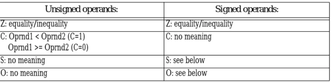
Table 27: Condition Code Settings After CMP
Unsigned operands: Signed operands:
Z: equality/inequality Z: equality/inequality C: Oprnd1 < Oprnd2 (C=1)
Oprnd1 >= Oprnd2 (C=0)
C: no meaning
S: no meaning S: see below
In the fourth (and final) example, cmp computes (+32767)-(-1). This produces (+32768), setting the overflow flag. Furthermore, the value wraps around to 8000h (-32768) so the sign flag is set as well. Since (S xor O) is zero, Oprnd1 is greater than or equal to Oprnd2.
6.5.4
The CMPXCHG, and CMPXCHG8B Instructions
The cmpxchg (compare and exchange) instruction is available only on the 80486 and later processors. It supports the following syntax:
cmpxchg reg, reg cmpxchg mem, reg
The operands must be the same size (eight, sixteen, or thirty-two bits). This instruction also uses the accumulator register; it automatically chooses al, ax, or eax to match the size of the operands.
This instruction compares al, ax, or eax with the first operand and sets the zero flag if they are equal. If so, then cmpxchg copies the second operand into the first. If they are not equal, cmpxchg copies the first operand into the accumulator. The following algorithm describes this operation:
cmpxchg operand1, operand2 if ({al/ax/eax} = operand1) then8
zero := 1 ;Set the zero flag
operand1 := operand2 else
zero := 0 ;Clear the zero flag
{al/ax/eax} := operand1 endif
Cmpxchg supports certain operating system data structures requiring atomic opera-tions9 and semaphores. Of course, if you can fit the above algorithm into your code, you can use the cmpxchg instruction as appropriate.
Note: unlike the cmp instruction, the cmpxchg instruction only affects the 80x86 zero flag. You cannot test other flags after cmpxchg as you could with the cmp instruction.
The Pentium processor supports a 64 bit compare and exchange instruction –
cmpxchg8b. It uses the syntax:
cmpxchg8b ax, mem64
This instruction compares the 64 bit value in edx:eax with the memory value. If they are equal, the Pentium stores ecx:ebx into the memory location, otherwise it loads edx:eax with the memory location. This instruction sets the zero flag according to the result. It does not affect any other flags.
6.5.5
The NEG Instruction
The neg (negate) instruction takes the two’s complement of a byte or word. It takes a single (destination) operation and negates it. The syntax for this instruction is
neg dest
It computes the following:
dest := 0 - dest
This effectively reverses the sign of the destination operand.
8. The choice of al, ax, or eax is made by the size of the operands. Both operands to cmpxchg must be the same size.
If the operand is zero, its sign does not change, although this clears the carry flag. Negating any other value sets the carry flag. Negating a byte containing -128, a word con-taining -32,768, or a double word concon-taining -2,147,483,648 does not change the operand, but will set the overflow flag. Neg always updates the A, S, P, and Z flags as though you were using the sub instruction.
The allowable forms are:
neg reg
neg mem
The operands may be eight, sixteen, or (on the 80386 and later) thirty-two bit values. Some examples:
; J := - J
neg J
; J := -K
mov ax, K
neg ax
mov J, ax
6.5.6
The Multiplication Instructions: MUL, IMUL, and AAM
The multiplication instructions provide you with your first taste of irregularity in the 8086’s instruction set. Instructions like add, adc, sub, sbb, and many others in the 8086 instruction set use a mod-reg-r/m byte to support two operands. Unfortunately, there aren’t enough bits in the 8086’s opcode byte to support all instructions, so the 8086 uses the reg bits in the mod-reg-r/m byte as an opcode extension. For example, inc, dec, and
neg do not require two operands, so the 80x86 CPUs use the reg bits as an extension to the eight bit opcode. This works great for single operand instructions, allowing Intel’s design-ers to encode several instructions (eight, in fact) with a single opcode.
Unfortunately, the multiply instructions require special treatment and Intel’s design-ers were still short on opcodes, so they designed the multiply instructions to use a single operand. The reg field contains an opcode extension rather than a register value. Of course, multiplication is a two operand function. The 8086 always assumes the accumula-tor (al, ax, or eax) is the destination operand. This irregularity makes using multiplication on the 8086 a little more difficult than other instructions because one operand has to be in the accumulator. Intel adopted this unorthogonal approach because they felt that pro-grammers would use multiplication far less often than instructions like add and sub.
One problem with providing only a mod-reg-r/m form of the instruction is that you cannot multiply the accumulator by a constant; the mod-reg-r/m byte does not support the immediate addressing mode. Intel quickly discovered the need to support multiplica-tion by a constant and provide some support for this in the 80286 processor10. This was especially important for multidimensional array access. By the time the 80386 rolled around, Intel generalized one form of the multiplication operation allowing standard mod-reg-r/m operands.
There are two forms of the multiply instruction: an unsigned multiplication (mul) and a signed multiplication (imul). Unlike addition and subtraction, you need separate instruc-tions for these two operainstruc-tions.
The multiply instructions take the following forms:
10. On the original 8086 chip multiplication by a constant was always faster using shifts, additions, and subtrac-tions. Perhaps Intel’s designers didn’t bother with multiplication by a constant for this reason. However, the 80286 multiply instruction was faster than the 8086 multiply instruction, so it was no longer true that multiplica-tion was slower and the corresponding shift, add, and subtract instrucmultiplica-tions.
Unsigned Multiplication:
mul reg
mul mem
Signed (Integer) Multiplication:
imul reg
imul mem
imul reg, reg, immediate (2)
imul reg, mem, immediate (2)
imul reg, immediate (2)
imul reg, reg (3)
imul reg, mem (3)
BCD Multiplication Operations: aam
2- Available on the 80286 and later, only. 3- Available on the 80386 and later, only.
As you can see, the multiply instructions are a real mess. Worse yet, you have to use an 80386 or later processor to get near full functionality. Finally, there are some restrictions on these instructions not obvious above. Alas, the only way to deal with these instructions is to memorize their operation.
Mul, available on all processors, multiplies unsigned eight, sixteen, or thirty-two bit operands. Note that when multiplying two n-bit values, the result may require as many as 2*n bits. Therefore, if the operand is an eight bit quantity, the result will require sixteen bits. Likewise, a 16 bit operand produces a 32 bit result and a 32 bit operand requires 64 bits for the result.
The mul instruction, with an eight bit operand, multiplies the al register by the oper-and oper-and stores the 16 bit result in ax. So
mul operand8
or imul operand8
computes:
ax := al * operand8
“*” represents an unsigned multiplication for mul and a signed multiplication for imul. If you specify a 16 bit operand, then mul and imul compute:
dx:ax := ax * operand16
“*” has the same meanings as above and dx:ax means that dx contains the H.O. word of the 32 bit result and ax contains the L.O. word of the 32 bit result.
If you specify a 32 bit operand, then mul and imul compute the following: edx:eax := eax * operand32
“*” has the same meanings as above and edx:eax means that edx contains the H.O. double word of the 64 bit result and eax contains the L.O. double word of the 64 bit result.
If an 8x8, 16x16, or 32x32 bit product requires more than eight, sixteen, or thirty-two bits (respectively), the mul and imul instructions set the carry and overflow flags.
Mul and imul scramble the A, P, S, and Z flags. Especially note that the sign and zero flags do not contain meaningful values after the execution of these two instructions.
Imul (integer multiplication) operates on signed operands. There are many different forms of this instruction as Intel attempted to generalize this instruction with successive processors. The previous paragraphs describe the first form of the imul instruction, with a single operand. The next three forms of the imul instruction are available only on the 80286 and later processors. They provide the ability to multiply a register by an immediate value. The last two forms, available only on 80386 and later processors, provide the ability to multiply an arbitrary register by another register or memory location. Expanded to show allowable operand sizes, they are
imul operand1, operand2, immediate ;General form imul reg16, reg16, immediate8
imul reg16, reg16, immediate16 imul reg16, mem16, immediate8 imul reg16, mem16, immediate16
imul reg16, immediate8 imul reg16, immediate16
imul reg32, reg32, immediate8 (3) imul reg32, reg32, immediate32 (3) imul reg32, mem32, immediate8 (3)
imul reg32, mem32, immediate32 (3)
imul reg32, immediate8 (3)
imul reg32, immediate32 (3)
3- Available on the 80386 and later, only.
The imul reg, immediate instructions are a special syntax the assembler provides. The encodings for these instructions are the same as imul reg, reg, immediate. The assembler simply supplies the same register value for both operands.
These instructions compute:
operand1 := operand2 * immediate operand1 := operand1 * immediate
Besides the number of operands, there are several differences between these forms and the single operand mul/imul instructions:
• There isn’t an 8x8 bit multiplication available (the immediate8 operands
simply provide a shorter form of the instruction. Internally, the CPU sign extends the operand to 16 or 32 bits as necessary).
• These instructions do not produce a 2*n bit result. That is, a 16x16 multi-ply produces a 16 bit result. Likewise, a 32x32 bit multimulti-ply produces a 32 bit result. These instructions set the carry and overflow flags if the result does not fit into the destination register.
• The 80286 version of imul allows an immediate operand, the standard
mul/imul instructions do not.
The last two forms of the imul instruction are available only on 80386 and later proces-sors. With the addition of these formats, the imul instruction is almost as general as the add
instruction11:
imul reg, reg imul reg, mem These instructions compute
reg := reg * reg
and reg := reg * mem
Both operands must be the same size. Therefore, like the 80286 form of the imul
instruction, you must test the carry or overflow flag to detect overflow. If overflow does occur, the CPU loses the H.O. bits of the result.
Important Note: Keep in mind that the zero flag contains an indeterminate result after executing a multiply instruction. You cannot test the zero flag to see if the result is zero after a multiplication. Likewise, these instructions scramble the sign flag. If you need to check these flags, compare the result to zero after testing the carry or overflow flags.
The aam (ASCII Adjust after Multiplication) instruction, like aaa and aas, lets you adjust an unpacked decimal value after multiplication. This instruction operates directly on the ax register. It assumes that you’ve multiplied two eight bit values in the range 0..9 together and the result is sitting in ax (actually, the result will be sitting in al since 9*9 is 81, the largest possible value; ah must contain zero). This instruction divides ax by 10 and leaves the quotient in ah and the remainder in al: