GENERAL
DESIGN
OF
CRITICALLY
DAMPED
GALVANO-METERS
By Frank Wenner
CONTENTS
Page
I. Introduction 211
II. Theory 212
1. Theoperation constants 212
2. Theintrinsicconstants 215
3. Operationconstants intermsof intrinsicconstants 216
4. Relationsbetweenoperation constants 223
III. Generaldesign 223
1. Numberofoperationandintrinsicconstants 223
2. Intrinsicconstantsintermsofoperation constants 225
3. Procedureinthe general design. 229
4. Designforcurrentsensitivity 231
5. Designforvoltagesensitivity 235
6. Designfor
Jidtsensitivity 238 7. Designfor fedtsensitivity 240
8. Detaildesign 241
IV. Summary 243
I.
INTRODUCTION
The
theory of the galvanometer,when
used under the criticallydamped
condition as a detector of constant voltage in a circuit offairly low resistance, is given in papers
by White
xand
Jaeger2
,
published about 10years ago. In these papers
some
oftheequa-tionswhich
we
shall useare given. However,we
wishto considersensitivities to current
and
voltage impulses as well as to steady currentand
voltage,and
in order that the mattermay
bepre-sented as a unit, the theory, in so far as it is needed in the design
of suchgalvanometers, will be given here.
That
is,we
shallshow
the relations between those constants of a galvanometer with
which the user is concerned
and
those constants with which themaker
is concerned.1PhysicalReview,19, p. 305; 1904.
2ZeitschriftfurInstrumentenkunde,23,p.261andp. 353, 1903;and AnnalenderPhysik,326, p.64, 1906.
212 Bulletin of the
Bureau
of Standards [Voi.13The
user is concerned with the period, the resistance whichmust
be putin series or parallel in order to give critical damping,and
the sensitivity to the quantity the galvanometer is used todetect or measure. These will be referred to as the operation
constants.
The maker
is concerned with the inertiaconstant, thedamping
constant, the restoring constant, thedynamic
constant,and
the resistance—
constants which dependupon
the kind ofmaterial used, the
number
of turns, the intensity of magnetiza-tion,and
the sizeand
the proportions of the parts ofthe galvano-meter. These will be referred to as the intrinsic or constructionconstants. These
two
sets of constants are necessarilyinterde-pendent,
and
a knowledge of the relations existing betweenthem
is necessary for an understanding of the subject of galvanometer
design.
We
shall, therefore,show
inwhat manner
each of theoperation constants depends
upon
the intrinsic constants.These relationswill thenbe used in establishing a procedure for
finding aset orsets of values forthe intrinsic or construction
con-stants, such as will give previously selected or specified values for
those of the operation constants which pertain to the class of
work
in which the galvanometer is to be used.The
finding ofsome
set of values for the intrinsic constants whichmay
bereal-izedin the constructionwithout unnecessarydifficulty,
and
whichwill give the specified values for the operation constants,
consti-tutes
what
we
call the general design of a galvanometer.The
matter will be considered primarily from the standpoint of the design of
moving
coil galvanometers of high sensitivity, thoughmuch
of the discussion will applyequally well tothe less sensitivegalvanometers with pointers
and
to galvanometers of themoving
magnet
type.The
way
inwhich particularvaluesfortheintrinsic constantsmay
be realized,and
other matters pertaining towhat
we
call thedetail design, can not be considered in this paper. II.THEORY
1.
THE
OPERATION
CONSTANTS
,
Galvanometers are used critically
damped
in four distinctclasses of measurements, in each of which the quantity to be
detectedor
measured
is different.In thefirst (which
we
shall referto as class A) it is thecurrent, or change in the current, in a circuitincluding the galvanometer.The measurement
of insulation resistanceby
the direct deflectionmethod
using a fairly high voltage isan example
of this class ofWenner) Galvanometer Design 213
measurements.
Here
the sensitivity which should be considered is to current.In the second (or class B) it is the change in the voltage in the circuit in which the galvanometer is connected which is to be
detected or measured.
The
change in voltage in thegalvano-meter circuit, on reversing the test current through a bridge
which is not exactly balanced, is
an example
of this class of measurements.Here
the sensitivity which should be considered is to voltage.3In thethird (or class C) it isthe quantityofelectricitysuddenly
passed through the circuit, including the galvanometer, which is
to be detected or measured.
The
comparison,ofthe capacities of condensersby
the ballistic throws given,when
they are charged tothesame
voltageand
dischargedthroughthesame
galvanometer,and
the comparison of capacitiesby
themethod
of mixtures, areexamples of this class of measurements.
Here
the sensitivitywhich should be considered is to impulsive rush of a quantity
of electricity q=\idt through the circuit including the
galva-nometer.
In the fourth (or class D) it is the time integral of the
electro-motive force in the circuit.
Examples
of this class ofmeasure-ments
are the comparison of magnetic fieldsby
the ballisticthrows they give,
when
a coil connected in series with the galva-nometer is suddenlyremoved
firstfrom
one fieldand
then fromthe other, or the comparison of
two
mutual
inductancesby
connecting their secondaries differentially in series with the
gal-vanometer
and
simultaneously reversing the currents in theirprimaries, adjusting the ratio of the currents so as to
make
theballistic throw zero.
Here
the sensitivity which should becon-sidered is to the fedt, where e (the voltage) is negligibly small
except for a very short time.
Besides the sensitivity to the quantity to be detected or
meas-ured the user of a galvanometer is concerned with the time
between the change
which
causes the deflectionand
the instantwhen
thedeflectionmay
be consideredto have reached a constantvalue; or, inthe caseof
an
impulse, theinstantwhen
thedeflectionhas reached a
maximum
valueand
must
be read.We
shall referto the first as the deflection period
and
the second as the ballisticperiod.
3Under anydefiiniteconditionsthe voltage sensitivityisequal tothecurrent sensitivitydividedby
theresistance. It,therefore,isnotnecessary to introducetheideaofa voltage sensitivity as distinctfrom the currentsensitivity. However,forthose cases inwhichitisthevoltage ratherthan thecurrentwhich
isthequantitytobemeasuredorwhichisthe independentvariable,theoperationofthegalvanometer
2i4 Bulletin of the
Bureau
of Standards [Voi.13 In allcasestheuserof agalvanometerisconcerned withthecon-ditions which give critical damping; that is, the conditions which
make
the motion of themoving
system just aperiodic (or justdeadbeat).
The
damping
often depends to averymarked
degreeupon
the resistance of the circuit into which the galvanometer isconnected.
The
resistance ofthecircuit (notincludingtheresist-ance of the galvanometer) in which the motion of the
moving
systemiscriticallydamped
willbereferred to asthe externalcritical resistance. Inmost
cases it is an important operation constantofthe galvanometer. If theapparatuswithwhich the galvanom-eterisbeingused has a resistance between the terminalsto
which
the galvanometer is connected different from the external critical
resistance, critical
damping
can betbrought about withmost
gal-vanometers of the
moving
coil typeand
withsome
of themoving
magnet
type. Insome
cases it is doneby
putting resistance inseries with the apparatus
and
galvanometer,and
in other casesresistance is put in parallel across the terminals to which the
gal-vanometer
is connected.Sometimes
it is desiredthatthegalvanometer be approximatelycritically
damped
without special adjustment for all readings orsettings oftheapparatuswith
which
it isused,when
theresistanceoftheapparatusbetween the terminalsto whichthegalvanometer
is connected varies with the setting through wide limits. This conditionis usually easily broughtabout
by
the use oftwo
resist-ances, one connected in parallel
and
the other connected in serieswiththe galvanometer.
By
aproper choiceoftheresistances, thedamping
can bemade
very nearly critical regardless of theresist-ance of the apparatus with
which
the galvanometer is used, butto doso necessarilyreduces the sensitivityverymaterially. It is
also possible to design a galvanometer so that, without a shunt or
parallel resistance, it will be approximately critically
damped
when
used in circuits of almostany
resistance. This isaccom-plished
by
the use of suitable airdampers
orby
the use of anauxiliary windingclosed
upon
itself.Sometimes
thewinding of amoving
coil galvanometeris placedon
a metal framewhich
servesalso as the auxiliary closed circuitwinding.
The
use ofan
auxil-iary winding
makes
the construction of a galvanometer to have ahigh sensitivity to voltage or voltage impulse
and
a shortdeflec-tion period
much
more
difficult.For
generallaboratory use it is desirablethat therate of change of thedamping
(or,more
specifically, the rate of change of theWenner] Galvanometer Design 215
circuit shall be small. Its value, or something equivalent to it,
might beconsidered as one ofthe operation constants. However, where a high or fairly high sensitivity is required it is better to
make
the adjustments necessary to give critical or approximatelycritical damping.
Where
this is done, the rate of change of thedamping
with change of the external resistance is of but littleimportance.
The
operation constants with which the user of a galvanometermay
be concerned,and
the symbols here used to represent them, are as follows:
R
=
the external critical resistance,T
d=
the deflection period, •T
b=
the ballistic period,Si
=
the currentsensitivity,S
e=
the sensitivity to voltage in acircuit having a resistancegiving critical damping,
S'e
=
the sensitivityto voltage in acircuit of resistanceexceeding the critical resistance,S
q=
the sensitivity to quantity or Jidt,S
n=the
sensitivity to jedt in acircuit having aresistance givingcritical damping,
and
S'n
=
the sensitivityto jedt in acircuit having a resistance in ex-cess ofthe critical resistance.For
any
one of the four classes ofmeasurements
we
needcon-sider only the appropriate period
and
sensitivity,and
usually theresistance of the apparatus between the terminals to which the
galvanometer is connected, or the external critical resistance of
the galvanometer.
2.
THE
INTRINSICCONSTANTS
As
hasbeen pointed out above, the values of the operationcon-stants necessarily
depend
upon
the size, shape,and
arrangementof the parts of thegalvanometer; thekind of material used in the
construction; the intensity of magnetization, etc.
That
is, theydepend
upon
the values of the intrinsic or construction constants.The
intrinsic constantsand
the symbols here used to representthem
are as follows:
K
=
theinertia constant (themoment
of inertia),
D=the
damping
constant (the ratio of the drag or retarding torqueon
themoving
system to its rate of displacement,with the circuit open)
f
21
6
Bulletin of the
Bureau
of Standards [Voi.i3£/
=
the restoring constant (the ratio of the restoring torque tothe displacement)
,
G
=
thedynamic
or displacing constant (the ratio of the dis-placing torque to the current),and
R
g=
the resistance of the galvanometer.Other symbols used
and
thequantities which they represent are as follows:
e
=
the voltage impressed in the circuit in whichthe galvanom-eter is connected,i
=
the current in the circuit in which the galvanometer is connected,$
=
the angular displacement ofthemoving
system, /=
the time,s
=
theresistanceoftheshuntacrossthegalvanometerterminals,r
=
theresistance in series withthe galvanometer,R'
=the
resistance in series with the galvanometer if in excess ofthe external critical resistance,
r'
=
the resistance of an auxiliary closedwinding,g
=
thedynamic
constant of an auxiliary closed winding,V
=the damping
constant with the auxiliary winding open,and
j, I, m, n,
and
p=
constants definedby
equations (66), (72), (49). (50),and
(83).3.
OPERATION CONSTANTS
INTERMS
OF
INTRINSICCONSTANTS
The
equation generally accepted as representing the motion of themoving
system of a galvanometer4is
K
%
+D
tt
+ue
=
Gi
«
where i is the current in the winding or coil. This equation,
however, is not in a convenient form, since as galvanometers are
generally used the current, *, is affected
by
the motion of themoving
systemand
so is notknown.
The
currentmay,
neverthe-less, be expressed in terms of the impressed voltage, that is, the
voltage having its seat in the apparatus with which the
galvano-meteris used, the voltage generated'
by
the motion ofthemoving
systemand
the constants of the circuit.As
is wellknown,
especially to thosewho
are familiar with theprinciples of operation of dynamo-electric machinery, that part
of the electrical
power
supplied to the galvanometer which is converted into mechanicalpower
is i times the generated orback
wen™*) Galvanometer Design 217
voltage. Also the mechanical
power
is the torque, Gi, times theangular velocity, -77* Since these
two
quantitiesmust
beequal it df)follows, therefore, that the generated voltage is
—
G-rr-Conse-quently, if
r+R
e is the resistance of the circuitand
e is theim-pressed voltage,
._ e
G
dBl
~r+R
e~7+R
s ~di(2)
This value of isubstituted inequation (1) gives as the equation of motion of the
moving
systemG
2V0
,™
Ge
-dt+ue
=TrR
s
(3)
If,for
any
reason,the galvanometerisshuntedby
aresistance, sy
the currentwhich
would
flowthroughthecoilincasethe impressed €Svoltage onlywereeffective,is
—
,
p
,p
anc*incasethe generated
voltage onlywereeffective,is
—
==—
;—
tt~37*
Where
R
e is the& J
rs-rrRg
+
sR
s dt sresistance ofthe galvanometer
and
r is theresistance of theappa-ratus with
which
it is used, or whichis in series with thegalva-nometer,
and
inwhich
there isthe impressedvoltage,e. Since the current through the coil is equal to that whichwould
flow as aresult of the impressedvoltageonly, plus thatwhich
would
flowasa result ofthe generated voltage only, itfollows that for this case the equation of motion is
K
d2°Jn
1
g(j
+
r)\de 1
no
Gse
1
a
These
may
beconsidered the general equations forthemotionof themoving
systems of galvanometers, excepting in those cases in which it is necessary to take into consideration either the effectsof self or
mutual
inductance or of capacity.That
the relations are at least approximately correct has been verifiedby
numerous
checksbetween values forconstants found
by
using theserelationsand
those valuesfoundby
othermeans. Itmust
notbe presumed, however, that they are correct to a high order of accuracy,and
it isnotnecessaryforthepurposeofthispaperthattheyshouldbe.
Equationsofthetypeof (3)
and
(4) areconsideredinelementarytextbooks
on
differential equationsand
in their solution there is obtained the auxiliary equationa2
21
8
Bulletin of the
Bureau
of Standards [Vol.13inwhich/, g,
and
hare thecoefficients of-r^'-jrand
6.The
formof the solution will depend
upon
whetherg2
>
4fh, g2
=
4fh or g2
<
4fhas well as
upon what
function e is of t.When
some
change ismade
in the apparatus with which the galvanometer is used sothatesuddenlyassumes a
new
constantvalue, orwhen
themoving
system of the galvanometer is released from a deflected position,the
moving
system takesup
thenew
position in theminimum
time (and the motion is said to be just aperiodic or criticallydamped)
if thetwo
roots of the auxiliary equation just referredto are equal.
That
is, ifG
2 r+
R,or if
+
D
=
2^KU
(5)The
particular value of r which satisfies equation (5) is theexternal critical resistance of the galvanometer
and
is designatedas R. Therefore it follows from equation (5) that
R
-iwki5
-*•
w
If the resistance of the apparatus with which the galvanometer
isused (measuredbetweenthe terminalstowhichthegalvanometer
is connected) is less than the external critical resistance, then
critical
damping
may
be brought aboutby
connecting the properamount
of resistance in series with the galvanometer. If theresistance of the apparatus with which the galvanometer is used
is
more
than the external critical resistance of the galvanometer, criticaldamping
may
usually be brought aboutby
connecting a resistance, s, of suitable value in parallel with the galvanometer. Inthis case the value of smust
be chosen so thatsR'/(s
+
R')=R
(7a)where R' represents the resistance of the apparatus.
If the galvanometer is critically
damped
without the use of a parallel resistance, itfollows from equations (3), (5),and
(7), thatWenner] Galvanometer Design 219
If a parallel resistance is used to bring about critical damping, it
follows fromequations (4), (6), (7),
and
(7a) thatK^
+2
^Ku
dj
f
+
ue^
G2
-
2R
^
+DR
^
(9)
at at
K
Lrand
if conditions are such that the galvanometer has noappre-ciable effect
upon
the magnitude of the current, i, in themain
circuit, then
K^
+
^
m
de+ue
^(P-
2R
gmJ
+
DR
g)idt2
dt
G
Here, since the galvanometeris shunted, i is notthe currentin its windingorcoil.
Equations (8), (9),
and
(10) are the general equations for themotion of the
moving
systems ofcriticallydamped
galvanometersand
are the equationson which
thework
which follows is based.Equation(8) applies incasecritical
damping
isbrought about with-out the useofa shunt,and
the impressed voltageistheindependent variable. Equation(1o)appliesincasethegalvanometerisshunted to bring about critical damping,and
the currentmay
beconsid-ered the independent variable. Equation (9) applies in caseit is necessary to use a shunt to bring about critical
damping and
when
the impressed voltage, rather than the current,must
beconsidered the independent variable. Equation (9) applies in the
cases which are intermediate betweenthose to whichequation (8)
applies
and
those towhich
equation (10) applies.Following a change in the value of the voltage or current from one steady value to another, there results a change in the steady
deflection. Ifthechangein voltageis Ae, orcurrentisAt,
and
theresulting change in the steady deflection is A0, the ratio of Ad
to Ae, or to Ai, is the sensitivity. Since,
when
the deflectiond2
9 do
becomes steady, both
-^
and
-r?are zero,inspection of equations(8), (9),
and
(10) shows that„
2^KU-D
5e=
GU
(II)G
2-2R
g
^KU
+
DR
g*
9~
R'GU
U;
c
G
2
-2R
g
^/KU+DR
g ,Si=
qU
(13)220 Bulletin of the
Bureau
of Standards [Voi.13where Si is the sensitivity of the galvanometer to current
when
connectedinacircuit ofhighresistance,
S
cis thesensitivityofthegalvanometer to voltage havingits seat in apparatus of resistance
equal to the external critical resistance of the galvanometer,
and
S'e is the sensitivity of the galvanometer to voltage in
appa-ratus having a resistance R' in excess of the external critical
resistance of the galvanometer, so that the galvanometer
must
beshuntedto bring aboutcritical damping.
If, instead of the voltage or current assuming a
new
constantvalue, it assumes a fairly large value for a very short time, after
which it becomes zero or assumes its former value, an impulse is given to the
moving
system. If the time of the impulse is very short in comparison with the time of throw, during the impulse thesecondand
third terms of the left-handmembers
of equations(8), (9),
and
(10) are very small in comparison with the first, somay
be neglected.Then
by
a single integration over the time ofthe impulseit follows that
de
2^/KU-D
C
,.
'
,
—J
edt (14)dt
G
dB
G
2-2R
e
^/KU
+
DR
and
7
M
G
2
-
2R
e
-jKU
+
DR
gC
;yK
dt
G
J
**
(l6)
While here
no
consideration is given to self-induced voltage, whichmay
during a part of the impulse be of thesame
order ofmagnitude as e, it
may
easily beshown
thatno
appreciable erroris introduced
on
thisaccount, unless the self-inductance is so largethat the electrical time constant of the circuit is appreciable in
comparison with the time ofthe
throw
of themoving
system. After the impulse the right-handmembers
of equations (8), (9),and
(10) are zero, so that for each of the three cases the equation of the motion of themoving
system is:
*S
+2
V^S
+W
=°
(17)The
solution ofthis equation (which is aspecial form ofequations(3)
and
(4) considered above) is as follows:
e
= C
1e-^uWt+ C
2te-^uirt (jg)where C\
and
C
2 are constants of integrationand
e is the base ofWenner] Galvanometer Design 221
impulse both 6
and
tmay
be considered zero. Differentiation ofequation (18) gives
-^L
-C
2t^U]Ke-^^jKt+
C
2€--yTmt
(19)
from which it follows that is a
maximum
when
t—
^KjU
orthat
T
h=
^/K/U
(20)where
T
b is the time of throw5 orthe ballistic period. It also d6
dt
follows that
C
2 is equal to the value of-77when
t=
o,which isthevalue of -7- as given
by
equation (14), (15),and
(16).The
sub-stitution of these values for
C
2and
t in equation (18) givese
_ij
d
1
fedt
eGL
2
KU\
S
*=
T^J+=
7ri\ 2-WTT\
(2i)_e_
G
2-2i?gv
S
»=
fedt=
eR'G^KU
K*2)_e_
g>-2R
eJku+dr
9 Sq=
Jidt
=
T^jWu
(23)where is the
maximum
value of 6 or themagnitude
of theballistic throw,
and
S
n, S'n,and
S
q are thesensitivities to voltageand
current impulses.From
equation (18) itwill be seen that the deflection reaches amaximum
and
thenbecomes
zero after a long time.However,
when
t=
(27r+ i)^KIU
the deflection has passedand
is then onlya little
more
than 1 per cent of itsmaximum
value. Since, inreturning from the deflected position, themotion follows the
same
law as
when
e is suddenly changed from one constant value toanother, the system accomplishes nearly 0.99 part of its final steady deflectionin atimeequal to 2ir^/K/U.
For
most
purposesoneis notconcernedin readingdeflect-ionsto as close as 1 percent,
so
we
shall consider thatr
d=
27rVx7Z7 (24)where
T
d is the deflection period.That
is,we
shall consider thedeflectionperiod tobethe
same
asthecompleteundamped
period.5Theeffect ofdamping,especiallycriticaldamping,uponthetimeofthroworballisticperiodandupon
theballisticsensitivityisdiscussedbyStewart,PhysicalReview,16, p. 158, 1902. Theeffect ofthe
damp-ingbythecurrent in acircuit oflowresistanceresultingfromthe voltage generatedbythemotionofthe
222 Bulletin of the Bureau of Standards [Vol.13
Collecting the equations representing the relations6
between
operation
and
intrinsic constants givesR
__&-R
s{2jKU-D)
2^Jku-d
5JT
d=
27njK/U
(26)t^tJk/u
(27)Se
=
^f^
(38)&-R
g(2jKU-D)
a e_
Wgu
K29)Si
^-R
g(2(VKU-D)
(3o)
u
"J
2-"7^T7l
(31)eG[_ -y/KU.
G>-R
g(2^KU-D)
•
bn_
eG^KUR'
(32)G*-R
g(2TJKU-D)
It
may
be ofinteresttonote thatincaseD
is verysmallincom-parison with
^KU
*>
Ik
S
°=
G\U
(34)and
and
in caseD
=
2^KU
Si
=
~
(36)S
«=
^m
(37)that is, the relations are
much
simpler than in the correspondingequations above.
6Itshouldbe understoodthatthemagnitudesofthe operation constants are tobeexpressed in th«
Wmner] Galvanometer Design 223
4. RELATIONS
BETWEEN
OPERATION CONSTANTS
The
fact that agalvanometer has but five intrinsic constants is evidence that all of the relations givenby
equations (25) to (33)can not be independent
and
that theremust
besome
relationsbetween the operation constants.
An
inspection willshow
thatthere is a simple relation between the ballistic
and
deflectionperiods,
and
between the four sensitivities. Expressing the otheroperation constants in terms ofR,
T
d,and
S
givesS'e=-g}Se (39)
Si
=RS
e (40)Sn=—jT-
(41)el d
c,
_
27rRSeR
r , x*
n~R'T
de-R'**
U2)
2irRSe
ei d
These equations
show
what
should be expected from agalvano-meter intended for use in class
B
work, if used with apparatushavingresistance between galvanometer terminals in excess ofthe external critical resistance of the galvanometer, or
when
used inclass A, C, or
D
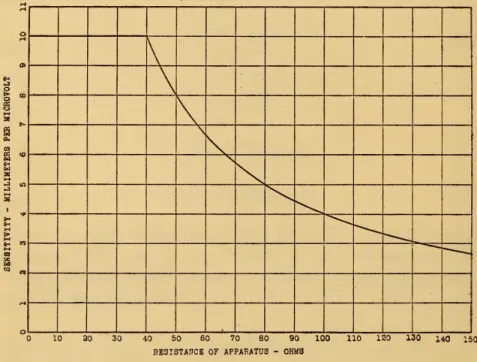
work.The
way
the sensitivity changes as the resistance of theappa-ratus (between galvanometer terminals) increases, keeping the
damping
critical eitherby
resistance in series or in parallel, isshown
in Fig. 1.The
pointwhere
the direction of the curveschanges abruptly is
where
it is necessary to change the resistance from series to parallel to keep thedamping
critical, orwhere
theresistance of the apparatus is equal to the external critical
resist-ance of the galvanometer.
III.
GENERAL
DESIGN
1.
NUMBER
OF OPERATION
AND
INTRINSICCONSTANTS
Equations (25) to (33) give the relations between the operation
and
intrinsic constants; that is, they enable one to calculate the values of the operation constants forknown
values of the intrinsic constants.But
in the general design of galvanometers224 Bulletin of the
Bureau
of Standards [Vol.13 the problem is to find values or sets of values for the intrinsic constants such as will give specified values for theopera-tion7 constants.
An
inspection of the equations shows that astheystand it
would
be difficultto usethem
for this purpose. For example, consider the design of a galvanometer for use with a bridgehavingaspecifiedresistancebetweenthe terminalstowhichthegalvanometer is to be connected, to give a specified deflection
per unit of voltage which
would
be between the galvanometerterminals ofthe bridge withthe galvanometercircuit open,
and
to\
\
\
\
\
1 2 3 4 5 6 7 8 9 10 1 LO 1 20 1 30 1 tO 15
RESISTANCE OF APPARATUS -0HM8
Fig. i.
—
Curve showing how the sensitivity to voltage changes asthe resistance of theapparatus, with which the galvanometer is used, is changed. Thecurveappliesfor a galvanometer having an external critical resistanceof40 ohms anda sensitivityof 10
millimetersper microvolt
come
to rest in adeflected orzero position in specifiedtime.The
problem, then, is to find a set ofvalues forthe intrinsic constants
such as will give the specified values for R,
T
d,and
S
e.7Thevaluesofthefive intrinsicconstantsofagalvanometermaybe determined from measurements
of fiveindependentoperation constants, orifoneormoreoftheintrinsicconstantsismeasureddirectly,
then the remainingintrinsicconstantsmaybe determined from measurementsoffour or fewerindependent operation constants. Theequationsrepresentingtherelationsbetweentheintrinsicconstantsand the
measuredoperation constantsmaybe usedforcalculatingthevaluesoftheintrinsicconstants necessary to givepreviously selected valuesforoperation constants. For example, wehave theequations given in thisBulletin,6,p.361, 1910. Thesecouldbe usedfordeterminingvaluesfortheinertiaconstant,the
dampingconstant,therestoring constant,andthedynamicconstant necessary to give previously selected valuesforthealternating-currentsensitivity,thealternating-voltagesensitivity,the direct-current sen-sitivity,andtheresonating frequency;the valuefortheresistanceofthe galvanometer being chosen
Wmner) Galvanometer Design 225
The
relations between the operation constantsand
the intrinsicconstants are given
by
equations (25), (26),and
(28). However,itwill be seen thatone can not readily choose a setofvalues such
that
when
they are substituted in these equations they give the value specified for each of the three operation constants.Even
if he should find a set of values which
would
give the specifiedvalues for the operation constants, they
would
probably be such aswould
make
the detail designand
construction unnecessarilydifficult. It is therefore desirable thatthe matter be investigated
forthe purpose of establishing, ifpossible, adefinite procedure for
finding values for the construction constants of galvanometers
such as will give specified values for the operation constants,
per-taining to each of the four different classes of
work
consideredabove. Itisalso importantthat the procedure enable us to
know
definitelythelimitstothe values foreachoftheintrinsicconstantsand
something of therelations between them.It has been
shown
above that there are only three independentrelations expressed
by
equations (25) to (33). It has also beenpointed out that for
any
class ofmeasurements
the user of agal-vanometer
is concerned, at most, with only three operationcon-stants, while the galvanometer has five intrinsic constants. This
suggests that possibly values for
two
ormore
of the intrinsic constantsmay
be chosen arbitrarily 8 or within limitsand
values
then calculated for the others such as will give specified values
for the operation constants.
2. INTRINSIC
CONSTANTS
INTERMS
OF OPERATION CONSTANTS
An
inspection of equations (25) to (33) shows that all can besatisfied with a zero value for both the resistance,
R
g,and
thedamping
constant, D.But
the construction of a galvanometer forwhicheitherR
gorD
iszeroisimpossible, thoughinsome
caseseither or both
may
bemade
so small as to haveno
appreciableeffect. If,however, the galvanometeristo
have
a high sensitivityto voltage or voltage impulse in a circuit of low resistance, then
neither can conveniently be
made
so small that its effectmay
beneglected.
Considering the external critical resistance R, the deflection
period
T
d, the sensitivityS
e, the resistanceR
g,and
thedamping
constant
D
as fixed, a solution of equations (25), (26),and
(28)8Aconsiderationofthematter fromthestandpointofthepoweravailableforproducingadeflection, the deflection period,andtheenergynecessary toproducea deflectionshowsthat, inmanycases,avalue
226 Bulletin of the
Bureau
of Standards [Vol.13for the inertia constant
K,
the restoring constant Z7,and
thedynamic
constant G, shows that the valuesfortheseconstants are complex (contain a realand
imaginary part) unlessIn
any
design possible of construction, therefore,D
must
have a value less than thismaximum
which dependsupon
the valuesdesired for the operation constants
and
the value chosen for theresistance
R
g, which, however, has no definite upper limit.The
valuesfor
R
gmay,
therefore, be chosenentirely arbitrarily, whilethe values for
D
must
be chosen less than a certainmaximum.
Values for others of the intrinsic constants, instead of these two,may,
within limits,be chosenarbitrarily,buttherelations9obtain-able
from
equations (25), (26),and
(28) which givemost
promise ofbeing of use in the design of galvanometers for use in classB
measurements
ared
=^s7r
(45)K
=^sM
(46)where
m=R/(R+R
g) (49)and
H
=
K[
1±
Vi-
47r2DS
e 2R/T
d2
m]
(50)The
±
sign in equation (50) shows that even after values are chosen forR
gand
D
there still remains a choice betweentwo
setsof values for
K,
U
fand
G. It willbe seen, too, thatifD
is smallincomparison withits
maximum
possible values, eachvalueinone set ismuch
smallerthan the corresponding value in the other set.9Equationssomewhatsimilar to
(45)to(48)were publishedbyJaeger(AnaalenderPhysik,326,p. 76, 1906)anddiscussedbrieflywithreference tochangesina particulargalvanometernecessaryforacertain changeinthe periodandtotalcriticalresistance. LaterDiesselhorst(ZeitschriftfurInstrumentenkunde, 31, p.250, 1911)usedthesameequationsforfindingvaluesfortheinertiaconstant,thedampingconstant, therestoringconstant,andthedynamicconstant necessary to givechosenvaluesforthesensitivity,the period,thetotal critical resistance,anda factordependinguponthelogarithmicdampingon opencircuit.
Neitherof theseauthorsseparatestheresistanceofthe galvanometerfromitstotal critical resistance.
Thatis,theydo notmakeacompletedistinctionbetweenthoseoftheoperation constantswithwhich the userofthe galvanometerisconcernedandtheintrinsicconstants, and, asthe equationsare stated,
itwould seemthatan unnecessaryconditionisimposedon accountofthewaythefactordependingupon
thelogarithmicdecrement on opencircuit enters. Inrealitynounnecessaryconditionisimposed,since theuserofa galvanometer does notcarewhatthedecrementon opencircuitisand,consequently,the designermaychooseanyvalueforthe factorwhich seemseasilyrealized in theconstruction.
Wmner] Galvanometer Design 227
If the smaller values are chosen, the construction
may
bemuch
more
difficultand
the completed instrumentmay
bemuch
more
delicate than is necessary, considering the values for its operation
constants
and
the values chosen for its resistanceand
damping
constant. Galvanometers in which
more
than half of the criticaldamping
iscausedby
the currentwhichflows inthemain
winding,as a result of the voltage generated
by
themoving
system, havethe larger values for
K,
U,and
G; others have the smallervalues.From
the standpoint of the design there is a decided difference,depending on whetherthe
+
orthe—
sign,whichoccurs hereand
later, is used,
and
sometimes it will be desirable to use oneand
sometimes the other.
In the design of galvanometers foruse in class
A
measurements
therelations obtainablefrom equations (25), (26),
and
(30),whichgive
most
promise ofbeing ofvalue, are«5S?
(5.)where
m=RI{R+R
s) (55)and
p
=
K[
1±
V
1-
4K
2Si2D/T
d'Rm]
(56) Here, in caseT
2Rm
is very large in comparison with ^tt2
S
2D
and
the negative sign ofequation (56) is used, expansion ofthe radical showsthat
p
may
beconsideredequalto7r2Si2D/T
d2
Rm
. This value
of
p
substituted in equations (52), (53),and
(54) gives47T
U
=
f
(58)G^
(59)Theseequations10
may
also beobtained directlyfrom therelations
D
=
2tIKU,T
d=
2ir^/K/Uand
Si=G/U
(60)10Inequations(59)and(75)wehaveconsideredthat m=i, whichwemaydo, sinceRislarge in com-parisonwithR£orthereisacondenserinseriesinthecircuit.
228 Bulletin of the
Bureau
of Standards Woi.13 which apply in case the instrument is criticallydamped
with themain
galvanometer circuit open.In the
same
way, itfollows from equations (25), (27),and
(31) that the relationsmost
likely to be of service in the design ofgalvanometers for use in class
D
measurements areu=
¥tS?r
(63)where
m=R/(R+R
e) (65)and
j=^[i±^i-e
2DS
n2
R/m]
(66) Finally from equations (25), (27),and
(33) it follows that therelationswhichgive
most
promise ofbeingof service in the designofgalvanometers foruse
m
classC
measurements
areD<§^
(6 7)k
-
2J
W
(68)
2Rml
U
=
e^T
b
(69) f 2RI
where
and
m=R/(R+R
g) (71)/=
X
[1±Vi
-e
2DS
q2
/Rm]
(72)
In case
Rm
is large in comparison with e2S
q2D
and
we
use thenegativesign ofequation (72), expansionofthe radicalshows that
we
may
consider l=
e2S
qD/4.Rm. This value of I substituted in equations (68), (69),and
(70) gives^
=
—
(73)U-gr
(74)Wenner) Galvanometer Design 229
Equations (57), (58), (59), (73), (74),
and
(75) apply only in those cases in which criticaldamping
is brought aboutundercon-ditions in which the voltage generated
by
the motionof themov-ing system has no appreciable effect
upon
the magnitude of the current in themain
winding. If thedamping
is supplied mainlyby
a current induced inan
auxiliary winding closedupon
itself,and
if gand
r' are itsdynamic
constantand
resistance,and
D'
is the
damping
constant with bothmain and
auxiliary windingopen, the constants ofthe auxiliary winding
must
be such that9
p
=
2^KU-D>
(76)If the galvanometer is to be used in a circuit
whose
resistance,R'
+R
8includingthatofthe galvanometer, isnotexcessively high, then for criticaldamping
it is necessary thatIt should be noted that the operation constants all appear
on
the left-hand side of the equations,
and
also that those ofequa-tions
numbered
(45) to (50) pertain to classB
measurements,those of equations
numbered
(51) to (59) pertain to classA
meas-urements, those of equationsnumbered
(61) to (66) pertain to classD
measurements,and
those of equationsnumbered
(67) to (75) pertain to classC
measurements.These equations
show
themaximum
value thedamping
con-stant of a galvanometer can have
and
have chosen values for itsresistance, external critical resistance, period,
and
sensitivity.They
alsoshow what
values the inertia constant, the restoringconstant,
and
thedynamic
constantmust
have in order that a galvanometermay
have chosen valuesfor its resistance,damping
constant,external critical resistance (and insome
casestheresist-anceofthe apparatuswith
which
the galvanometeris to be used),
and
the particular periodand
sensitivity withwhich
we
may
beconcerned.
The
equationsmay,
therefore,be used in the general design ofgalvanometers.3.
PROCEDURE
INTHE
GENERAL DESIGN
Since a value for the resistance of the galvanometer
may
be chosen arbitrarilyand any
value taken for itsdamping
constant,less than a certain
maximum
shown
by
the first of each set ofequations,
much
is leftto thejudgment
of the personmaking
the230 Bulletin of the
Bureau
of Standards [Voi.13 designand
constructionand
theperformance oftrie galvanometer,in matters other than the values of its operation constants, will
depend in
no
small degreeupon
thejudgment
used.In carryingoutageneral designthefirstthing to dois to choose a value for the resistance of the galvanometer,
and
if one isentirely at a loss in the matter, he
may
take it equal to that ofthe rest of the circuit in
which
the galvanometer is to be used,that is, take
R
s equal to R. This
makes
m, which occurs inmost
of the equations, equal to one-half. Using this value for
m
inthe first of the set of equations, pertaining to the class of
work
in which it is intended that the galvanometer shallbe used, gives
the
maximum
valueD
can have. TakingD
equal to half thismaximum
valueand
using the -f- sign inthe last equation of theset
makes n
(or I orp
orj) equal to 0.85. Using these values form
and n
the corresponding values forK,
U,and
G
can readily becalculated. This gives us a set of values for the intrinsic
con-stants such as will give the specified values forthe operation
con-stants.
While it is notto be
presumed
that this particular set ofvalueswill lend itself
most
readily to the detail designand
construction,it
may
be used inmaking
a preliminary detail design.A
littleconsideration of the detail design will show, in
most
cases, that the resistance of the galvanometer can, to advantage, bemade
much
less thantheexternal criticalresistance,
and
in amoving
coiltypeofgalvanometer, of low external critical resistance, the larger part
of the resistance
may
be in the suspensions rather than in thecoil. Ordinarily, such a preliminary detail design will enable us
to chooserevisedvalues for
R
gand
forD, suchthat withthe corre-sponding values forK,
U,and
G
they constitute a set of valuesfor the intrinsic constants
which
aremore
easily realized in thedetail*design
and
construction.To
getthe bestresults in the general design of a galvanometer,one should be reasonably familiar with the performance
and
con-struction of
somewhat
similar galvanometers(know
both theiroperation
and
their intrinsic constants)and
know
fairlydefinitelythe properties of the materials available for the construction of
the proposed galvanometer. Usually the general design should
be considered as subject to slight modifications until, the size of
the mirror, the size of the wire,
number
of turns ofand
dimen-sions of the winding, the strength of the magnetic field, the kind
ofmaterial, section
and
length ofthe suspensions,and
most
of theWenner) Galvanometer Design 231
4.
DESIGN FOR CURRENT
SENSITIVITYHere
the problem is to design a galvanometer which shall besuitable foruseinclass
A
measurements, thatis, in thosemeasure-ments
in which the galvanometer serves to detect or measure a small current in a circuit of high resistance. (See p. 212.) Ingeneral, this resistance
may
bepresumed
to be so high thatno
account need be taken of theeffect of the resistance of the
galva-nometer, or ofthe voltage generated
by
the motion of itsmoving
systemupon
themagnitude
of thecurrent. Stating the situationin a slightly different way, the
power
which can reasonably bedissipated in the resistance of the galvanometer (Rsi
2
) plus that
which can be converted into mechanical
power
(i e', where e' isisthe voltage generated
by
the motionofthemoving
system) issosmallincomparison with the
power
suppliedto thecircuit thatno account need be taken ofit.We
may,
therefore,make
theresist-ance, or
any
other of the intrinsic constants, practically as largeas
we
please.More
specifically, the problem is to design a galvanometer to be criticallydamped
in a circuitof very high resistanceand
haveacertain deflection period
and
current sensitivity.Equations (51) to (56), inclusive, givethe relationswhich
must
be satisfied inthe general design. Here,
R
istheresistancewhich,when
connected in series with the galvanometer, gives criticaldamping.
With
the galvanometer connected in a circuit of veryhigh resistance, it is the value of the shunt necessary to produce
criticaldamping. Ifthere isa second windingforwhich theratio of
dynamic
constant to resistance is such as will, in itself, give critical damping, then the shuntmay
be dispensed with, that is,R
may
be taken as indefinite. There is, therefore,no
definitelimit for the value of R. It is desirable, however, either to have
a
shunt ofonly moderately high resistance or to dispense with itentirely. If
R
is to be only moderately high, the first matter to be decidedupon
in the general design is the resistance ofthegal-vanometer. In this choice
much
willdepend
upon
the sizeand
properties (especially magnetic impurities
and
thickness of theinsulation) of thewire available forwinding the coil; the size
and
kind ofwire available forthe suspensions; the period, sensitivity,
size of mirror,
and
ruggednessof the instrument desired;and
theskill of the person
who
is to construct it. If the sensitivity is tobe high the winding should be of fine wire, the
number
of turns should be fairly large,and
the magnetic field should be strong. However, there is little orno
advantage in increasing thenumber
232 Bulletin of the
Bureau
of Standards [Vol.13of turns to the point at which the inertia constant increases as
rapidly as the
dynamic
constant.Having
decidedupon
a value for the resistance of thegalva-nometer, experienceshowsthat the externalcriticalresistance
may
be chosen from 2 to 20 timesR
g, the resistance of thegalvanom-eter (10 to 100times
R
gif the deflection period is long). Next,avalue
may
be chosen for thedamping
constant D. This valuemust
necessarily be less than themaximum
corresponding to thechosen values for the resistances
and
specified values for thedeflection period
and
current sensitivity asshown
by
equation(51).
The
corresponding values for the inertia constantK,
therestoring constant U,
and
thedynamic
constantG
may
thenreadily be calculated
from
equations (52) to (56), inclusive, usingthe positive signinequation (56).
The
preliminary values fortheintrinsic constants, found in this way,
may
be modified to suitbetterthe conditions
met
in the detail design.As
an example,assume
thata galvanometeris desired tohave adeflection period of six seconds, a current sensitivity of 2000
mm
per microampere
and
be criticallydamped
with a resistance in parallel of 2000ohms;
that is, a galvanometerfor whichT
d=
6, Si=
2000,and
R
=
2000Here
the sensitivityand
resistance areexpressed in the unitscom-monly
used, whileup
to this point it has beenassumed
that allquantities
would
be expressed in cgs units or in thesame
systemof units.
Expressing the current sensitivityintermsof thedeflectionona
scale 1 meterinfront ofthe mirrorinmillimeters permicroampere,
the resistances in ohms, the deflection period in seconds,
and
theintrinsicconstants, other than the resistance of the galvanometer,
in cgs units, requires a change in the constant in the equations expressing the relations between the various constants.
Making
this change in equations (51) to (56), which give the relations which
must
besatisfiedin this case,theymay
bewrittenasfollows:
D<^
(78)K
_
o.3,TJ*mp
^
v
^2.
7T*Rmp
(go)
wenner] Galvanometer Design 233
where
ni=R/(R+R
g) (82)and
P
=
y
2[i±^i-S
iD/TRm]
(83)From
experience with other galvanometers,we
would
judgethat it
would
be convenient tomake
the coiland
suspensionsin such a
way
as to have a resistance in the neighborhood of200 ohms. Using this value for
R
gand
2000 for R, it follows from equation (82) that772=0.91
and
using this value form
and
the specified values for theopera-tion constants, it follows from equation (78) that
L><o.oi6
Taking
D
=
0.008gives, from equation (83),
£=0.85
Values for
K,
U,and
G
are then obtained from equations (79), (80),and
(81), using these values form
and p and
the specifiedvalues for the operation constants. Proceeding in this
way
givesK
=
o.o2j, 77=o.oo8, £7=
0.029G
=
330000,and
R
g=
200These constitute a set ofvalues for the intrinsic constants which givethe specified values for the operationconstants.
These values for the period, current sensitivity,
and
external critical resistance are those givenby
the Leeds&
Northrup Co.11fortheirtypeof high sensitivity galvanometer.
The
value chosenfor the resistance, however, is considerably less than the value
which theygive. Consequently,theirvaluesforthe otherintrinsic constants
must
differ slightly from these values.It is to be understood that these values for the intrinsic
con-stants would, in all probability, be changed slightly to better
satisfy conditions
met
in the detail design. However, a change of ahundred
ohms
in the resistance of the galvanometer, so thatwe
could use a particular size of wire thatmight
be available,would
not necessitateany
very appreciable changes in the other intrinsic constants. If, onconsidering the detail design, itshouldbefound that it
would
bebetter tohave
all theintrinsicconstants larger, all thatwould
be necessarywould
be to choose acorre-spondinglylarger value for R.
234 Bulletin of the
Bureau
ofStandards \voi. i3 In designing a galvanometer to be criticallydamped
without a shunt, the simpler equations (57), (58),and
(59)may
be used.Changing the constant of the latterto correspondwith the unit of
sensitivity usedhere, these
may
be rewritten as followsK
=
o.oSoTdD
(84)U
=
3.*4D/Td (85)G
=
i57oo5iD/T
d (86)It will be noticed that the resistance of the galvanometer does
not appear here
and
that there are only three conditions to besatisfied. Therefore, in addition to the resistance
any
other one ofthe intrinsicconstantsmay
be chosenentirely arbitrarily.The
problem of the design, however, is not materially different from
that just considered, except that
some means must
be providedfor producing the necessary damping, since conditions are such
that the voltage generated
by
the motion of themoving
system canhave
no
appreciable effectupon
themagnitude
of the current in the winding. If this is to be accomplishedby
an auxiliary winding closedupon
itself, the constants of this windingmay
bereadily calculated after
K
and
U
are determined, providing D',the
damping
constant with bothmain and
auxiliary windingsopen, is small in comparison with
tJKU
or isknown
approxi-mately.From
equation (76) it follows that the relation whichmust
be satisfied is£-[2VWC-Z>']XlO>
(87)where g is the
dynamic
constant of the auxiliary winding in cgsunits
and
/
its resistance in ohms.In case one does not care to
work
outthe details ofa design to such an extent as will give specified values for the operationcon-stants
and
yet wishes to construct a galvanometer having a highcurrent sensitivity
and
a short deflection period, he shouldmake
the ratio of the value for the
dynamic
constant to the value forthe inretia constant12
as large as practicable. This follows
from
equations (84)
and
(86), which shows that for thiscase^
2=
YXio-7
(88)
Wenmr] Galvanometer Design 235 5.
DESIGN
FOR VOLTAGE
SENSITIVITYHere
the problem is to design a galvanometer which shall besuitable for use in class
B
measurements, that is, in thosemeas-urements in which the galvanometer serves to detect or measure a small voltage in a circuit of fairlylow resistance. (Seep. 213.)
The
resistance of the galvanometer and, during the time thedeflection is changing, the voltage generated
by
the motion of itsmoving
system have amarked
effectupon
the magnitude of thecurrent,
and
consequentlyupon
the magnitude of the torqueacting
upon
themoving
system.Usually the apparatus with which the galvanometer is used (and in which, under definite conditions, there is a voltage to be
detected or measured) has a certain resistance between the terminals to which the galvanometer is connected. If this
resist-ance is
R
and
the voltage e, themaximum
current thatmay
bedrawn from
these terminals is e/Rand
thepower
whichmay
bedissipated in apparatus connected between the terminals can not
under
any
condition bemore
than e2i^R. This, therefore, is themaximum
possible value forpower
available for producing adeflection of the galvanometer.
However, except
by
a motion of themoving
system, this elec-tricalpower
can not be converted into mechanical power. There-fore, theamount
of energy available forproducing a deflection ofthegalvanometeris T&e2
l<\R.
The
potentialenergyrepresentedby
the deflection
must
necessarily be considerably less than thisamount, since the displacement of the
moving
system takes place according to a particular law, asshown
by
equation (18), so that theback
or generated voltage is not, except at certain instances, of themagnitude
necessary for galvanometer toreceive themaxi-mum
available power. Further,some power
is lost in theresist-anceofthewinding
and
in air friction,and
intheauxiliary closedwinding, if there isone.
The
problem, therefore, is very differentfrom
that which hasjust been considered. Instead of having all the
power
one mightcare to dissipate in theresistance of the galvanometer
and
use inproducing adeflection, the
amount
ofpower
available is definitelylimited. Consequently all possible
ways
in which thepower
isused, such as in the resistance of the winding, in the
damping
frameorauxiliarywinding, in case thereisto beone, aswell as in airfriction
and
in twisting the suspensions or turning the magnet,236 Bulletin of the
Bureau
of Standards [Vol.13it
must
considered. It might, therefore be better to speak of thepower
sensitivity, or possibly the energy sensitivity, rather thanthe voltage sensitivity.
More
specifically, the problem is the designof a galvanometer to be criticallydamped when
connected toan
external circuit having a resistance R, to have a certainsensitivity
5
e to voltage in this circuit,and
to have a certaindeflection period Td.
Equations (45) to (50) give the relations which
must
besatis-fied. If the sensitivity isexpressed as the deflection
on
ascale 1meter in front of the mirror caused b}^ an impressed voltage of
1 microvolt, the resistances are expressed in
ohms
and
the otherquantities are expressed in cgs units, these equations
may
bewrittenas follows:
(89)
(90)
(91)
(92)
(93) (94)
where
and
L
}<
Tim
=
S
e 2
R
K
=
o^2Td
3
mn
S
e*RU
= i2.yTdmnS
e 2R
G
= 64oooTan
Sem
=^R/(R
S+R)
=
K[ii:^i-DRSe
2/Til
m\
The
first thing to be done is to decideupon
a value forR
s, theresistance of the galvanometer. This value
when
substituted inequation (93) gives a value of m.
Then
from
equation (89) themaximum
possiblevalueforD, thedamping
constant, isobtained.Choosing a smaller value for D, a value for
n
is obtained from equation(94). Thesevaluesform
and
n,and
thespecifiedvaluesforthe operation constants substituted in equations (90), (91),
and
(92) givevalues for the remaining intrinsicconstantsK,
U,and
G. It willbe observedthat the higher thesensitivityand
theshorterthe deflection period desired,
and
the higher the resistance of theapparatuswith whichthegalvanometer isto be used,
and
alsothe higher the resistance of the galvanometer is made, the smaller13D,
K,
U,and
G
must
be. For galvanometers of high sensitivityand
short period the difficultiesmet
in the detail designand
con-struction
become
greater the smallerwe
attempt tomake
theWenner] Galvanometer Design 237
inertia
and
restoring constants. In the general design of such galvanometerswe
should thereforeaim
to keep these constantsabout as high as is possible. Since particularvalues usually are desired for
T
d, R,and
S"e the only placewhere there can bemuch
choice is in the values of
m
and
n, which should be kept as nearunity as is practicable.
That
is, the values forR
eand
D
shouldbe so chosen that
R
s is small in comparison with R,D
is small in comparison withitsmaximum
possible value,and
the plus sign inequation (94) should be used.
The
procedure given here is one thatwe
have been using for the past three years,and
a fairlylarge
number
of general designs have been made. In a few casesthe corresponding detail designs have been
worked
outand
thegalvanometers constructed.
For example, let us consider the general design of a
moving
coilgalvanometer to be critically
damped
withan
external resistance of 20 ohms, tohave
adeflection period of 10 seconds,and
a sensi-tivity of 20mm
per microvolt, that is, haveR
=
20,T
d=
10,and
S
e=
20From
experience in the construction of sensitive galvanometerswe know
that for the suspensions of this galvanometer very finewire
must
be used,and
that itwould
be difficult tomake
theirresistance
much
less than 10 ohms.We
alsoknow
that thereneed be
no
difficulty inmaking
the coil so as tohave
aresistanceof less than 5 ohms. Taking
R
s=
i2 gives, from equation (93),m
=0.62,and
this value ofm
gives, from equation (94),D
<o.oo8.From
experience in the construction ofsomewhat
similargalva-nometers
we
know,ifwe
are tousean
approximately uniformradialfieldwith acoil 8 to 10
mm
wideand
10to 15mm
long,we
would
have difficulty inmaking
thedamping
constantmuch
less than0.004. Taking this value for
D
gives, from equation (94),n
=
0.85. Values for the remaining intrinsic constants are then
obtained from equations (90), (91),
and
(92)by
substitutingthese values for
m
and n and
thespecifiedvaluesforthe operationconstants. This procedure gives as acomplete set ofvalues
i£
=
0.021, 12=0.004,U
=
0.0084G
=
19 500,and
R
=
12
The
galvanometers14which
w
re designate as type
M
have (withcertain adjustments) very nearly these values for their intrinsic
constants.