AUSTRALIAN JOURNAL OF BASIC AND
APPLIED SCIENCES
ISSN:1991-8178 EISSN: 2309-8414 Journal home page: www.ajbasweb.com
Open Access Journal
Published BY AENSI Publication
© 2016 AENSI Publisher All rights reserved
This work is licensed under the Creative Commons Attribution International License (CC BY).
http://creativecommons.org/licenses/by/4.0/
To Cite This Article: V.Arulalan and Dr.R. Dhanasekaran, Closed loop Implementation of Ultra Sparse Matrix Converter for Wind Energy Conversion System. Aust. J. Basic & Appl. Sci., 10(1): 498-504, 2016
Closed loop Implementation of Ultra Sparse Matrix Converter for Wind
Energy Conversion System
1V.Arulalan and 2Dr.R. Dhanasekaran
1Research Scholar, St.Peter’s University, Dept. of Electrical and Electronics Engineering, Chennai-600 054, Tamilnadu, India. 2Professor & Director, Research Syed Ammal Engineering College, Ramanathapuram-623502, Tamilnadu, India.
Address For Correspondence:
V.Arulalan, Research Scholar, St.Peter’s University, Dept. of Electrical and Electronics Engineering, Chennai-600 054, Tamilnadu, India.
A R T I C L E I N F O A B S T R A C T
Article history:
Received 10 December 2015 Accepted 28 January 2016 Available online 10 February 2016
Keywords:
SVPWM, PIC16F87XA
Microcontroller, Photo coupler.
Background: This Paper presents hardware model of the ultra-sparse matrix based converter system for AC/AC conversion system. Here the shoot through capability is implemented using z-source inverter for improving voltage boost at the dc output side of Matrix Converter. The inrush current and capacitor voltage stress is reduced and is verified using the hardware model. The output across the RL load is presented. Here the Pulse input to the switches are achieved using Programmable Interface Controller. The Photo coupler based gate driver is used for generating the pulses for the Sparse rectifier bridge.
INTRODUCTION
Sparse matrix converters eliminate the use of multiple step commutation procedure used in the conventional matrix converter systems. Ultra Sparse Matrix Converters consists of the less number of switches and the Driver potentials compared to the very sparse and the sparse matrix converters (Ekrem Karaman, et al., 2012). Thus the complexity in generating the input pulses are reduced. The Sinusoidal Pulse Width Modulation Technique is implemented in the rectifier stage while the Space Vector Pulse Width Modulation is used in the inverter side. Here the AC/DC/AC system is used, which consists of the DC link capacitor fed from the series Z-source inverter circuits. The DC link is not present in the case of Direct AC/AC Conversion Systems (Ekrem Karaman, Fen Niu, and Andrzej M. Trzynadlowski, 2012).
The Closed Loop Control System can be implemented for the proposed type of Ultra-Sparse Matrix based Wind Energy Converter system (Santoshkumar, M., Rangani, Hiren H Patel, 2015). Thus the LC Filter is used in the Wind Energy System in order to reduce the harmonic content at the input of the system. The requirement of high frequency DC to DC Transformers or Linear Transformers can be eliminated in this type of AC-DC-AC conversion Systems (Amit, K Singh, et al., 2015).
The Ultra-Sparse Matrix based Converter can also be used for the Induction Heating applications without any energy storage elements (Haseena Banu, H., R. Gandhi, 2015). The six switch topology uses the simple clamp circuit with a single diode and a single transistor (Schonberger, J., et al., 2007). The Clarke Transformation can be used for the three phase quantities into two phase quantities (Park, Inverse Park and Clarke,). The SVPWM uses the three phase inputs displaced by 120° with each other.
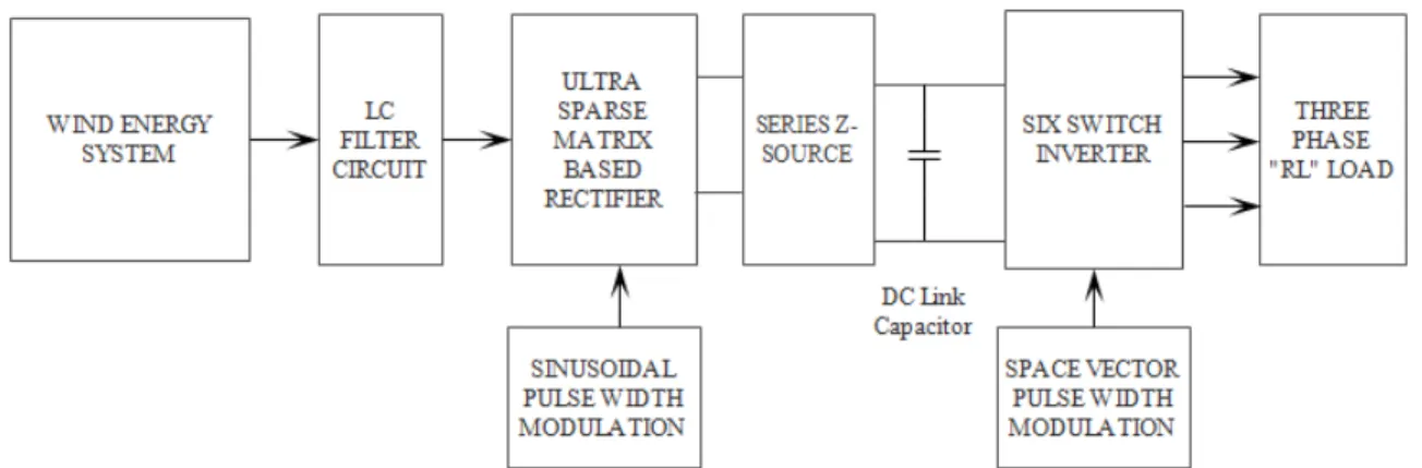
Block Diagram Of Proposed Matrix Based Wind Energy Conversion System:
Programmable Interface Controller is used in the Hardware for the generation of the pulses and given to the rectifier switches. The “RL” type of Load is connected to the output of the System. The proposed type of Matrix Converter topology uses only nine transistors and eighteen diodes (http://www.diodes.com). The Vertical Axis Wind Turbine is better in comparison to the Horizontal Axis Wind Turbine due to the case that it avoids the requirement of yaw system (Sajjad Hossain Rafin, S.M., Thomas A. Lipo, Byung-il Kwon, 2014). The design aspects such as the blade shape and position plays vital role in the efficient operation of wind energy conversion system. The kinetic energy input to the Wind turbine is converted to the mechanical input to the gear box and is used to drive the generator for the extraction of electrical energy and the betz limit governs the maximum power output from the wind energy conversion system (Aravind, C.V and G.P. Ramesh, 2013). Power Semiconductor devices improves the power conversion efficiency by reducing the cost and number of devices used for power conversion (Ramesh, G.P. and C.V. Aravind, 2015).
Fig. 1: Proposed Ultra Sparse Matrix Converter based Wind Energy Conversion System
Hardware Components Used:
Components used in the Proposed System:
Table 1: Components used in the proposed type of Matrix Converter System
S.NO Components Quantity
1 Ac socket 1
2 1amp Bridge rectifier 1
3 470mf 25v capacitor 1
4 7805 regulator 1
5 10mf 25v capacitor 1
6 330 ohm resister 1
7 LED 1
8 0.1 capacitor 2
9 22pf capacitor 2
10 10MHZ crystal oscillator 1
11 40 pin IC Base 1
12 100 ohm resister 1
13 Micro switch 1
14 PIC16f874A IC 1
Driver boards:
Table 2: Driver components used
S.NO Components Quantity
1 TLP 250 1
2 IN4007N Diode 1
3 1000mf capacitor 2
4 1k resistor 1
5 100 ohm resistor 1
6 8 PIN IC 1
The table 1 and table 2 shows the components used in the proposed type of matrix converter system and the driver used respectively. Thus the detail about the PIC Microcontroller and other components used is explained below.
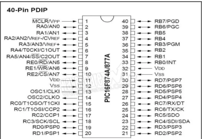
The PIC Controller used here is the PIC16f874A. It is a 40-Pin IC and has the several units including Input / Output Ports, Control Pins including reset, power, clock, Processor (CPU), Memory (RAM, ROM, EEPROM), Serial and parallel ports, Timers, Analog-to-digital (A/D) and digital-to-analog (D/A) converters. It has several Serial communication interfaces including USART, SPI, I2C, CAN. It comes with the several types of packages including DIP, PLCC, SOIC, QFP. Thus the PIC microcontroller used consists of the analog inputs. Fig. 2 shows the Pin Configuration of the PIC Microcontroller and the input signals and clock signals and Timers used (http://toshiba.semicon- storage.com/info/docget.jsp?pid=TLP250&lang=en&type=datasheet).
Fig. 2: Pin Configuration of the PIC16F87A Micro Controller
Diode:
The Diode used in the rectifier side consists of the IN4007. The diodes ranging from the IN4000 to IN4007 are one amp rated and are low speed rectifier diodes. The IN4007 diode is rated at 1 Ampere and 1000 Volts and has a long reverse recovery time. It has the advantages including High Current Capability, Low Forward Voltage drop, Peak Surge Voltage rating of 30A, Low reverse leakage current and it is a lead free finish. Fig.3 represents the diagrammatic representation of the IN4007 Diode used in the rectifier section.
Fig. 3: IN4007 Diode
Gate Driver Circuit:
Fig. 4: Pin Configuration of TLP250 Gate driving circuit used.
Fig 4 represents the Pin Configuration of the TLP 250 gate driving circuit. TLP250 gate drive is suitable for Power MOSFET and IGBT switches. It consists of a GaAlAs light emitting diode and an integrated photo detector. Here the pin 1 and 4 are No Connection, pin 2 and 3 are anode and cathode respectively, while pin 5 is Ground while pin 6 and 7 is Output Voltage Vo and pin 8 is Vcc. TLP250 consists of a photo coupler at the input of the Gate drive circuit.
Input threshold Current If = 5mA(max) Supply Current Icc = 11mA (max) Supply Voltage Vcc = 10 – 35V Output Current Io = 1.5A (max) Switching time (tpLH/tpHL) = ±1.5µs(max.) Isolation Voltage = 2500 Vrms
Maximum Operating Insulation Voltage = 890 Vpk.
The Gate Driver is based on the Photo Coupler where it consists of a GaAlAs based light emitting diode and an integrated photo detector (TLP250 TOSHIBA).
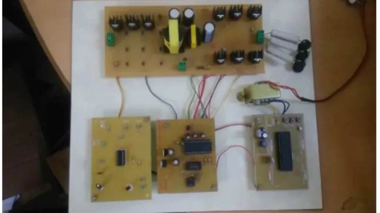
Hardware Implementation: Hardware Configuration:
Fig. 5: Proposed Model of the Ultra-Sparse Matrix based Wind Energy Conversion System
The Fig.5 represents the entire setup of the Proposed System. Permanent Magnet Synchronous Generator is used in the Wind Energy System. The PMSG used in the proposed system is 400 Watts Three Phase Generator.
Fig. 6: Entire setup of the Proposed Matrix based Converter System.
Fig. 7: PIC16f874A used for the pulse generation
Fig. 8: TLP250 Gate Driver.
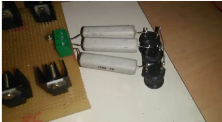
Fig. 9: Rectifier and Inverter used for the Proposed System
Fig. 11: Three Phase Supply across the Input side of the Matric Converter
Fig. 12: Output Voltage Waveform across the RL Load
Transformer used here is 12 Volt Step Down transformer. The output is divided into two outputs. One is +5V supplied to the PIC microcontroller and +12V supplied to the TLP250 gate driver circuit. Output Voltage is obtained at 90 Volts. Fig.7 represents the PIC16f874A Microcontroller used for the generation of the pulse. The Fig.8 represents the TLP250 Gate Driver. Fig 9 uses the Bridge inverter and the sparse matrix converter. Fig. 10 represents the RL load connected across the output side. Thus the Resistive load of 1K ohm and power rating of 10 Watts is used. The Fig. 11 represents the Three Phase AC waveform given to the input side and the Fig. 12 represents the Output Voltage waveform across the RL load of the inverter Section. The Proposed type of converter system can also be improved by using the closed loop configuration using a specific type of controller
Conclusion:
The Series Z-Source based Ultra-Sparse Matrix Converter is implemented for the Wind Energy Conversion System. The inrush current across the DC link Capacitor is limited compared to the existing topologies by using the effective shoot through capability of Series Z-Source Network Configuration. The Proposed System is implemented in hardware and the output shows the reliability of the Proposed Converter system and applications of the proposed type of converter system includes grid line application for low harmonic output and the renewable energy applications. The advantages of the proposed type of converter system includes the reduced complexity in the pulse generation, reduced switching losses, low harmonic content, reduced cost and ease of implementation.
REFERENCES
Ekrem Karaman, Mehdi Farasat, and Andrzej M. Trzynadlowski, 2012. Matrix Converter with a Series Z-Source”, IECON 2012 - 38th Annual Conference, IEEE Industrial Electronics Society, pp: 6093-6098.
Santoshkumar, M., Rangani, Hiren H Patel, 2015. Control Scheme for Ultra Sparse Matrix Converter”, International Journal of Current Engineering and Scientific Research (IJCESR), 2(7): 30-37.
Amit, K Singh, Pritam Das, S.K. Panda, 2015. A Novel Matrix Based Isolated Three Phase AC-DC Converter with Reduced Switching Losses”, Applied Power Electronics Conference and Exposition (APEC), IEEE, pp: 1875-1880.
Haseena Banu, H., R. Gandhi, 2015. A high efficient induction heating using ultra sparse matrix converter”, International Journal of Scientific & Engineering Research, 6(4): 393-398.
Schonberger, J., T. Friedli, S.D. Round and J.W. Kolar, 2007. An Ultra Sparse Matrix Converter with a Novel Active Clamp Circuit”, Power Conversion Conference - Nagoya, 2007 (PCC '07), IEEE, pp: 784-791.
Ekrem Karaman, Fen Niu, and Andrzej M. Trzynadlowski, 2012.Three-Phase Switched-Inductor Z-Source Matrix Converter0, Applied Power Electronics Conference and Exposition (APEC), 2012 Twenty-Seventh Annual IEEE pp:1449-1454.
TLP250 TOSHIBA Photocoupler based Gate Driver Datasheet, Toshiba Corporation.
WebLink : http://toshiba.semicon- storage.com/info/docget.jsp?pid=TLP250&lang=en&type=datasheet PIC16F87XA Data Sheet 28/40/44-Pin Enhanced Flash Microcontrollers, Microchip Technology Inc. Weblink: http://www.diodes.com/_files/datasheets/ds28002.pdf
Sajjad Hossain Rafin, S.M., Thomas A. Lipo, Byung-il Kwon, 2014. Novel Matrix Converter Topologies with Reduced Transistor Count, Energy Conversion Congress and Exposition (ECCE), pp: 1078-1085.
Aravind, C.V and G.P. Ramesh, 2013. Design Aspects of Blade Shape and Position for the Vertical Axis Wind Turbine, International Journal Of Technology And Engineering Science, IJTES, 1(6): 1001-1007.
Ramesh, G.P. and C.V. Aravind, 2015. Design Aspects of Blade Shape and Position for the MAGLEV Vertical Axis Wind Turbine”, Power Electronics and Renewable Energy Systems, Lecture Notes in Electrical Engineering, Springer India, 326: 933-940.