Effect of Surface Treatment and Crystal Orientation on Microstructural Changes
in Aluminized Ni-Based Single-Crystal Superalloy
*1Kazuki Kasai
1;2;*2, Hideyuki Murakami
2, Seiji Kuroda
2and Hachiro Imai
11Division of Materials Science and Engineering, Graduate School of Shibaura Institute of Technology, Tokyo 135-8548, Japan 2Coating Materials Group, National Institute for Materials Science, Tsukuba 305-0047, Japan
The effect of pre-surface treatment and crystal orientation on microstructural changes in the aluminized 4th generation Ni-based single-crystal superalloy TMS-138 was investigated. The substrate superalloy was cut along the {100} and {110} planes on which three kinds of surface finishing, such as grit blasting, mechanical polishing and electro-polishing were conducted prior to the conventional high-activity aluminizing process. A thermal cycling test at 1373 K revealed that heavy deformation of the substrate surface by grit blasting gave rise to the formation of a secondary reaction zone (SRZ) in the vicinity of the interdiffusion zone/substrate interfaces. When the surfaces were finished by electropolishing, voids were formed in the vicinity of the interdiffusion zone/substrate interfaces. It was also found that accelerated formation of SRZ and voids was observed along theh110idirections rather than theh100idirections during the thermal cycling test. The difference in morphological changes of substrates can be related to the residual stress introduced by the surface finishing.
[doi:10.2320/matertrans.M2010439]
(Received December 28, 2010; Accepted June 6, 2011; Published July 21, 2011)
Keywords: secondary reaction zone (SRZ), thermal barrier coatings (TBC), aluminizing, nickel-based single crystal superalloys
1. Introduction
Currently, there is a strong requirement to reduce carbon dioxide emissions in order to protect the earth against deterioration of environments. One of the effective ways to cope with this problem is to increase the efficiency of thermal engines. Since an increase in operating temperatures of such engines is a simple solution, the development of components with higher heat and oxidation resistance is essential. Therefore, a various kind of heat and oxidation resistant coatings have been developed to be placed on various Ni-based single-crystal superalloy substrates which are currently used for the hottest section of jet engines.1,2)
To enhance the oxidation resistance, the aluminizing process is regarded as one of the effective coating techniques. This coating technique provides an aluminum enriched layer on the substrate surface, by a reaction between gaseous aluminum halides and a metal substrate. This method has some advantages such as simple apparatus set-up, high cost performance and uniform formation of coatings.
However, it is reported that when aluminized turbine blades are exposed to high temperature, microstructural changes in the coating layer and at the substrate take place by the interdiffusion of alloying elements.3) One example of
such microstructural changes is the formation of a secondary reaction zone (SRZ). The SRZ is defined as the region between the inter-diffusion zone (IDZ) and the substrate, characteristically showing a high density of fine topological close-packed phase (TCP) precipitates, and a high angle boundary to the substrate.4) In other words, the SRZ is a
region consisting of the re-crystallized substrate with TCP precipitates. Since the SRZ formation can destroy the and
0 coherent two-phase microstructure, which accordingly leads to a deterioration of mechanical properties of the
substrate, understanding of formation kinetics of SRZ is important.5–8)
On the other hand, microstructural anisotropy of Ni-based superalloys which were fabricated by the directionally solidified method can cause anisotropic microstructural differences. There is another important report which revealed that surface re-crystallization formed during service at elevated temperatures was promoted by the residual stress that had been applied to the components during machining.9)
It is thus easily anticipated that surface crystal orientation, and/or pre-surface treatments prior to coating can affect the SRZ formation kinetics. However, to the best of our knowledge, there are very few reports investigating such effects, except for the authors’ group.10,11)
In this study, microstructural changes of aluminized superalloy (4th generation Ni-based single crystal superalloy, TMS-138) were investigated, focusing on the effect of surface crystal orientation and pre-surface treatment. In particular, microstructural changes of grit-blasted, mechan-ical polished and electropolished {100}, {110} surfaces were investigated.
2. Experimental Procedure
The so-called 4th generation Ni-based single crystal superalloy, TMS-138, whose composition is Ni-6.7Co-3.6Cr-1.9Mo-2.1W-13.8Al-2.1Ta-0.04Hf-1.7Re-1.2Ru in at%, was used as a substrate material. After the precise determination of crystal orientation by the back Laue reflection method, the substrate superalloy was cut into an octahedral rod by the electron discharge machining (EDM) method, of which width is 1.9 mm and length is 18 mm. The [001] direction was set to the longer direction. According to this method, each of the side surfaces faces to either {100} or {110} plain group. All the side surfaces were then mechan-ically polished followed by the electro-polishing in order to get rid of the surface residual stress. As shown in Fig. 1, among the 8 side surfaces of the octagonal rod, 5 surfaces,
*1This Paper was Originally Published in Japanese in J. Japan Inst. Metals
74(2010) 19–23.
*2Graduate Student, Shibaura Institute of Technology
((11110) to (110)) were grit-blasted using high purity alumina powder of 425–500mm. The blasting pressure was5105Pa and the working distance was 10 cm. Finally three of the eight side surfaces, including two grit blasted and one electropolished, were again mechanically polished up to #1200 Emery finish. In this manner, three kinds of surface finishing were applied to two kinds of surface orientation in one piece of specimen, which made it possible to investigate the effect of surface finishing and surface crystal orientation on the microstructural changes.
After those surface finishing treatments, pack cementation of aluminum was carried out. The specimen was embedded in a heat resistant container with mixture of metal powders and NH4Cl reactant. The composition of the powder is
24.5 mass% Al (45–106mmin particle size) 24.5 mass% Cr (45mm), 49 mass% Al2O3 (15–63mm) and 2 mass% NH4Cl.
This container was put into a vacuum furnace and evacuated down to1101Pa at an ambient temperature by a rotary
pump. After this evacuation, dry Ar gas was introduced into the furnace up to 1105Pa. The evacuation-Ar flush
operation was repeated three times. Then the furnace was heated up to 1273 K in 1 h and kept at 1273 K for 5 h in Ar flow at the rate of 200 mLmin1.
In order to understand the microstructural changes by heating, a thermal cycling test was carried out. One thermal cycle consists of heating for 1 h at 1373 K and cooling at an ambient temperature for 20 min in air atmosphere. The test was conducted up to 100 thermal cycles. After the cycling test of 1, 3, 10, 30 and 100 cycles, the specimen was sliced along the (001) surface, and the sliced surfaces were analyzed by SEM, EDX and EBSD.
3. Results
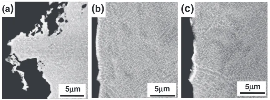
Figure 2 shows cross-sectional backscattered electron (BSE) images in the vicinity of the specimen surfaces after each surface treatment. As shown in Fig. 2(a), the =0
[image:2.595.51.286.73.174.2]coherent two-phase structure was heavily distorted by the grit blast treatment. On the other hand, such kind of surface distortion was not induced by other treatments as shown in Fig. 2(b) and (c).
Figure 3 shows cross-sectional BSE images after the aluminizing treatment. After the aluminizing process, the
electropolished
blasted
Mechanically-polished
(0 1 0)
(1 1 0)
(1 0 0)
(1 1 0) (1 1 0)
(1 0 0)
(0 1 0) (1 1 0)
4.6mm (0 0 1)
Fig. 1 Schematic view of the specimen used in this study.
(a
)
5
µ
m
(c)
5
µ
m
5
µ
m
(
b
)
Fig. 2 Surface cross-sectional morphologies of the specimen after each surface treatment: (a) blasted (1110), (b) electropolished (1110) and (c) mechanical polished (11110).
Aluminized
Coating
substrate
SRZ
(a)
(b)
Inter diffusion
zone(IDZ)
[image:2.595.82.514.409.569.2] [image:2.595.107.490.612.769.2]formation of SRZ beneath the interdiffusion zone was observed in the grit blasted (1110) surface as indicated by the arrows in Fig. 3(a). The rougher surface in Fig. 3(a) is attributed to the surface roughness before the aluminizing treatment. For the electropolished surfaces, the formation of SRZ was not observed as shown in Fig. 3(b).
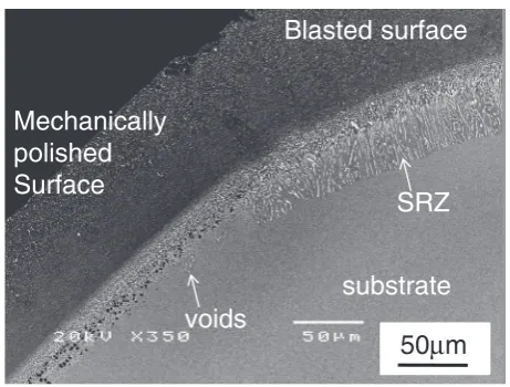
The following thermal cycle test revealed that the micro-structural changes varied depending on region. Typically two types of changes were observed: one is the SRZ formation region and the other is the void formation region. The formation of SRZ and void was clearly observed in Fig. 4, which is the cross-sectional BSE images showing both blasted (1110) and mechanical polished (1100) surfaces after 10 cycles.
The increase in number of thermal cycles gave rise to the expansion of both SRZ formation region and void formation region. Figure 5 shows cross-sectional BSE images of (a) blasted (1110) and (b) electropolished (100) in the surface region after 100 cycles. As shown in Fig. 5(a), SRZ formed uniformly and reached as thick as 110mm under the interdiffusion zone (IDZ) for the blasted (1110) surface, while a number of voids were grown to form a layer for the electropolished (100) surface. The size and number of voids both increased with increasing thermal cycles. It was also found that once the voids formed, subsequent SRZ formation was rarely observed in the void formation zone. Similar
tendency was observed for all the other void forming surfaces.
Figure 6 summarizes the average thickness of void formation layers in the seven kinds of surfaces. It was revealed that the thickness of void formation layer of {110} surfaces was thicker than that of {100} surfaces for electro-polished and mechanically electro-polished surfaces of five kinds, expect for the blasted (010) and mechanically polished (1100), which exhibited formation of both SRZ and voids.
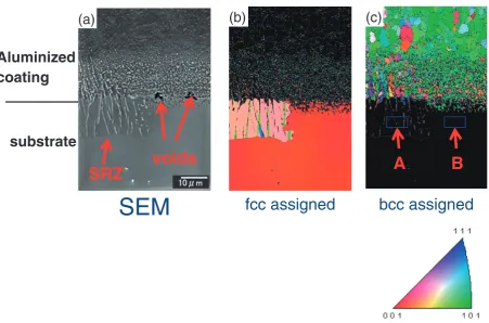
In order to further understand the differences in micro-structure between the SRZ formation region and the void formation region, EBSD analysis was conducted for the region where both SRZ and voids were observed. In Fig. 7, the upper part corresponds to the coating layer followed by the interdiffusion zone, and the lower part corresponds to the single crystal Ni-based superalloy substrate. It should also be noted that orientation maps are displayed from the normal direction (ND), which is normal to the observation surface. While it is clear from the region assigned as fcc that the substrate was single-crystal, the orientation of SRZ region was different from that of the substrate. This suggests that re-crystallization of the single-crystal substrate took place in the vicinity of the original substrate surface. On the other hand, such a change in crystal orientation was not observed in the void formation region. It was also found that void formation region lies in the vicinity of the interface between
bcc-substrate
voids
SRZ
Blasted surface
Mechanically
polished
Surface
50
µ
m
Fig. 4 Cross-sectional BSE images of the specimen after 10 heat cycles showing the edge region between blasted (1110) and mechanically polished (1100).
substrate SRZ
IDZ
100µm
Aluminized Coating
voids
100µm
(a)
(b)
Fig. 5 Cross-sectional BSE images after 100 heat cycles: (a) blasted (1110) and (b) electropolished (100).
A
verage thickness of
void formation zone,
t
/
µ
m
(010)(110)(100)(110)(010)(110) (100)
0 10 20 30 40 50 60 70 80
blasted
Electro polished
Mechanically polished
SRZ SRZ
[image:3.595.53.284.69.244.2] [image:3.595.320.534.72.235.2] [image:3.595.105.492.308.435.2]structured coating layer and the substrate. Finally, the EDS area analysis for the region A and B in Fig. 7(c) was conducted. The result is summarized in Table 1, Al concen-tration in the SRZ region was is higher than that in the void formation region.
4. Discussion
Figure 8 shows a schematic summary of the microstruc-tural changes after 100 heat cycles. The SRZ was observed in the grit-blasted (1110) surface and in its two neighboring sides, i.e. blasted (010) and mechanically polished (1100) surfaces. There were no SRZ regions observed in the other surfaces. Additionally, the SRZ was observed at the edge region between the blasted (010) and (110) surfaces, and mechanically polished (1100) and (11110) surfaces. In this manner, typically two different kinds of microstructural changes, i.e. SRZ and void formation, were observed in a single substrate. To the best of the authors’ knowledge, there were very few reports showing such a phenomenon. This section discusses about the possible mechanism of these microstructural changes.
As already mentioned in the experimental procedure section, the grit blast treatment was conducted on the five
side surfaces from (11110) to (110) with the central surface being oriented normal to the [1110] direction. Therefore, the surface strain can be the highest on the (1110) surface, followed by the (010) and (1100) surfaces, while the (110) and (11110) surfaces can have lower surface strain after the grit blast treatment. In addition, considering that the edge region tends to become the stress concentration site, it is rational that the SRZ formation zone coincided with the region having higher surface strain. The formation of SRZ in the mechan-ically polished (1100) surface can be explained by the fact that the mechanical polishing could not perfectly remove the surface deformation region formed by the grit blasting.
The SRZ formation was observed both in the blasted (1110) and (010) surfaces, and the growth rate of SRZ was higher in the blasted (1110) than the (100) surface. However, no formation of SRZ was observed in the electropolished (1110) and mechanically polished (11110) surfaces, having small residual strain. This result indicates that the effect of surface residual strain is more significant on microstructural changes
fcc assigned
bcc assigned
SEM
SRZ
voids
substrate
Aluminized
coating
(a)
(b)
(c)
A
B
[image:4.595.74.526.68.366.2]Fig. 7 (a) Cross-sectional SEM image of blasted (1110) after 3 heat cycles and corresponding orientation map assigned as (b) fcc and (c) bcc, respectively.
Table 1 Composition of region A and B in Fig. 7 (at%).
Al Ru Cr Co Ni Hf Ta W Re A 15.24 0.78 3.7 6.18 66.79 0.37 3.02 2.4 1.52 B 12.51 1.53 3.93 6.62 68.45 0.51 2.35 2.45 1.65
(0 1 0)
(1 1 0)
(1 0 0)
(1 1 0) (1 1 0)
(1 0 0)
(0 1 0) (1 1 0)
electropolished blasted
Mechanically-polished SRZ
[image:4.595.306.548.418.505.2] [image:4.595.46.292.427.472.2]rather than that of surface crystal orientation, even though the formation kinetics of SRZ is affected by the crystal orientation of the substrate surface and though the growth rate of SRZ is higher along the h110i directions than the
h100i directions.11) More systematic investigations such as
quantification of surface strain by the surface treatment would confirm this hypothesis.
It was also found that void formation was more accelerated on the {110} surfaces than the {100} surfaces. This may be attributed to the orientation relationship between aluminized coatings and superalloy substrates, and to the difference in thermal expansion coefficients, which will be investigated by the authors’ group in the future.
While SRZ can be regarded as microstructural changes accompanying recrystallization, void formation did not accompany recrystallization as shown in Fig. 7. According to the result that SRZ was already observed in the as aluminized state, it is likely that the void formation could play a role as retarding the formation and growth of SRZ, which indicates the region with recrystallization.
The results obtained in this study suggest the possibility that there had been some differences in microstructure and elemental distribution between the SRZ formation zone and the void formation zone in the as-aluminized stage. For-mation kinetics of SRZ could be explained in the following manner. Surface strain having been introduced during the grit blasting promoted recrystallization of the substrate in the vicinity of the substrate/coating interface when the alumi-nizing process proceeds. The recrystallization accelerated the interdiffusion between Al and Ni via grain boundaries formed and accordingly promoted the formation of SRZ. As shown in Table 1, the Al concentration in the SRZ formation region is higher than that in the bottom of the void formation area can be caused by the acceleration of Al diffusion from the coated region by grain boundaries.
On the other hand, formation kinetics of voids could be explained in the following manner. As shown in Fig. 7, the thermal expansion coefficient of a Ni-based single-crystal superalloy substrate, having fcc structured=0coherent two
phases, is larger than that of a bcc structured aluminized coating layer.12)Therefore, during the cooling process after aluminizing, this difference in thermal expansion coefficient caused tensile stress between the substrate and coating. To relax this stress, it is expected that recrystallization (for-mation of SRZ) or void for(for-mation can occur in the substrate. During heating in the thermal cycling process, Al in the coating layer diffuses inward and the alloying elements of the substrate, especially Ni, diffuse outward from the substrate to the coating layer. In the case of the NiAl intermetallic phase, diffusivity of Ni is higher than that of Al on the Ni-rich side, and vice versa.13) In the aluminized coating layer close to
IDZ, the composition of NiAl became Ni-rich and thus the outward diffusion of Ni is dominant rather than the inward
diffusion Al. In addition, when the specimen was heated, the compressive stress was applied to the substrate and the tensile stress being applied to the coating layer, resulting in the accelerated outward diffusion of elements. These can be the cause of void formation.
In summary, microstructural changes in aluminized Ni-based single-crystal superalloy during thermal cycling were investigated in this study. In the interface between the coating and substrate, SRZ and voids were formed. And these microstructural changes were affected by the surface treat-ment and substrate crystal orientation. However, these microstructural changes may be also affected by several parameters such as substrate composition, phases and aluminizing conditions. In order to understand the effect of such parameters, further investigation should be conducted in the future.
5. Conclusions
Microstructural changes of the aluminized 4th generation Ni-based single-crystal superalloy TMS-138 was inves-tigated, focusing on the surface crystal orientation and pre-surface treatment. The following results were obtained.
(1) Depending on the crystal orientation and pre-surface treatment, SRZ formation region and void formation region were observed.
(2) SRZ was mainly observed in the grit blasted surfaces which is regarded to have higher residual stress. (3) No SRZ formation was observed in the void formation
zone.
(4) Accelerated formation of SRZ and voids was observed along theh110idirections.
REFERENCES
1) H. Murakami: Kinzoku76(2006) 1012–1016.
2) S. Kuroda and H. Murakami: Kinzoku75(2005) 741–745. 3) S. Hayashi and T. Narita: Materia Japan46(2007) 225–228. 4) A. Suzuki, C. M. F. Rae, M. Yoshida, Y. Matsubara and H. Murakami:
Proc. Eleventh Int. Symp. on Superalloys sponsored by TMS, (the Minerals, Metals and Materials Society, 2008) pp. 777–786. 5) A. Sato, Y. Aoki, M. Arai and H. Harada: J. Japan Inst. Metals71
(2007) 320–325.
6) D. K. Das, B. Gleeson, K. S. Murphy, S. Ma and T. M. Pollock: Mater. Sci. Technol.25(2009) 300–308.
7) D. K. Das, K. S. Murphy, S. Ma and T. M. Pollock: Metall. Mater. Trans. A39(2008) 1647–1657.
8) S. Wo¨llmer, S. Zaefferer, M. Go¨ken, T. Mack and U. Glatzel: Surf. Coat. Technol.167(2003) 83–96.
9) M. Okazaki, I. Ohtera and Y. Harada: Metall. Mater. Trans. A 35 (2004) 535–542.
10) H. Murakami and T. Sakai: Scr. Mater.59(2008) 428–431. 11) T. Sakai, M. Shibata, H. Murakami and S. Kuroda: Mater. Trans.47
(2006) 1665–1670.