University of Warwick institutional repository: http://go.warwick.ac.uk/wrap
A Thesis Submitted for the Degree of PhD at the University of Warwick
http://go.warwick.ac.uk/wrap/2768
This thesis is made available online and is protected by original copyright. Please scroll down to view the document itself.
DESIGN OF INTERLOCKING BRICKS
FOR ENHANCED WALL CONSTRUCTION
FLEXIBILITY, ALIGNMENT ACCURACY
AND LOAD BEARING
A thesis submitted in partial fulfilment of the requirements of
the degree of Doctor of Philosophy in Engineering
By
ii
TABLE OF CONTENTS
LISTOFFIGURES... V LISTOFTABLES ... VII LISTOFGRAPHS ... IX ACKNOWLEDGEMENT ... X ABSTRACT ... XI DECLARATION ... XII LISTOFABBREVIATIONSANDVARIABLES ... XIIICHAPTER 1 ... 16
1.0 INTRODUCTION ... 16
1.1 BACKGROUND ... 16
1.1.1 HOUSING DEFICIT ... 16
1.1.2 POVERTY ... 17
1.1.3 APPROPRIATE HOUSING SOLUTIONS ... 18
1.1.4 EARTH WALLING ... 18
1.1.5 MORTARLESS WALL BUILDING ... 19
1.2 RESEARCHJUSTIFICATION ... 20
1.3 RESEARCHMETHODOLOGY ... 22
1.4 STRUCTUREOFTHETHESIS ... 22
CHAPTER 2 ... 24
2.0 LITERATUREREVIEWFORMORTARLESSCONSTRUCTION ... 24
2.1 HISTORYOFINTERLOCKINGBRICKS ... 24
2.2 INTERLOCKINGMORTARLESSBRICKS/BLOCKSFORHOUSECONSTRUCTION ... 26
2.2.1 DEFINITIONS ... 27
2.2.2 INTERLOCKING HOLLOW-BLOCKS ... 28
2.2.3 THAI INTERLOCK BRICKS ... 30
2.2.4 SOLBRIC SYSTEM FROM SOUTH AFRICA ... 31
2.2.5 HYDRAFORM SYSTEM FROM SOUTH AFRICA ... 33
2.2.6 BAMBA SYSTEM FROM SOUTH AFRICA ... 35
2.2.7 AURAM SYSTEM FROM INDIA ... 37
2.2.8 TANZANIAN INTERLOCK BRICK (TIB) SYSTEM ... 38
2.3 WALLPERFORMANCEFACTORS ... 40
2.4 CHARACTERISTICSOFMORTARLESSWALLING ... 42
2.5 SELF-ALIGNMENTANDINTERLOCKING ... 43
2.6 WALLALIGNMENTACCURACY ... 46
2.7 LOADBEARINGCAPACITYOFMORTARLESSWALL ... 47
2.8 PRODUCTIONOFBRICKS/BLOCKS ... 56
2.9 SELECTIONOFSUITABLESOILFORSTABILISATION ... 57
2.9.1 SHRINKAGE BOX FOR SOIL TESTING ... 59
2.10 BRICKCURING ... 62
2.10.1 BRICK HANDLING ... 62
2.10.2 CURING CONDITION ... 63
2.11 SUBJECTSWORTHYOFFURTHERANALYSIS ... 64
2.12 CONCLUSIONTOLITERATUREREVIEW ... 72
CHAPTER 3 ... 73
3.0 RESOURCEUSEIMPLICATIONSOFEMPLOYINGMORTARLESSTECHNOLOGY ... 73
3.1 INTRODUCTION ... 73
3.2.1 CEMENT ... 75
3.2.2 CEMENT REDUCTION ... 77
3.2.3 CEMENT & GREENHOUSE GASES ... 78
3.2.4 SOIL ... 80
3.2.5 WATER ... 80
3.3 MTPERFORMANCEANDCOSTREDUCTION ... 82
3.3.1 ELEMENTS OF COST REDUCTION ... 82
3.3.2 WALL CONSTRUCTION STAGES ... 83
3.4 SUMMARY ... 88
CHAPTER 4 ... 89
4.0 INTERLOCK-BRICKWALLINGFLEXIBILITY ... 89
4.1 INTRODUCTION ... 89
4.1.1 BACKGROUND ... 90
4.1.3 BRICKWORK PATTERNS ... 92
4.1.4 BRICK SHAPE ... 92
4.1.5 WALL CONFIGURATIONS ... 93
4.2 BRICK-SETDESIGNTOENHANCETHEFLEXIBILITYOFINTERLOCKWALLING ... 94
4.2.1 COMMON PART-BRICKS ... 94
4.2.2 HALF-BRICK WALL ... 95
4.2.3 DEVELOPMENT OF A NEW PART-BRICK ... 96
4.3 USESOFC½B’SINTHEASSEMBLYOFINTERLOCKINGBRICK-WALL ... 99
4.3.1 PIERS ... 99
4.4 FORMATIONOFNEWBOND ... 102
4.4.1 SHOKSE BOND ... 103
4.4.2 LIJUJA BOND ... 107
4.5 SPECIALBRICKS ... 110
4.5.1 TEE BRICK (TB) ... 110
4.5.2 ANGLE BRICKS ... 112
4.5.3 CURVED WALLS ... 114
4.6 IMPROVEMENTINFLEXIBILITYACHIEVED ... 116
4.6 SUMMARY ... 117
CHAPTER 5 ... 119
5.0 BRICKIRREGULARITIESANDTHEIRIMPLICATIONSFORWALLQUALITY ... 119
5.1 BRICKIRREGULARITIES ... 119
5.2 SOIL-CEMENTBRICKCURINGPRACTICE ... 124
5.3 SUMMARY ... 126
CHAPTER 6 ... 127
6.0 THERELATIONSHIPBETWEENWALLALIGNMENTANDBRICKGEOMETRIC IMPERFECTION ... 127
6.1 INTRODUCTION ... 127
6.1.1 THE EXPERIMENTAL OBJECTIVES... 128
6.2 PRIMARYPREPARATIONFOREXPERIMENT ... 129
6.2.1 MOULD DESIGN AND FABRICATIONS... 130
6.2.2 BRICK PRODUCTION ... 136
6.2.3 DETERMINATION OF BRICK CHARACTERISTICS ... 139
6.3 REPRESENTINGBRICKGEOMETRYINALIGNEDPOSITION ... 150
iv
6.4 RESEARCHTECHNIQUESFOREXAMININGBRICK-TO-COLUMNALIGNMENT RELATIONSHIP ... 156
6.5 THEORETICALANALYSISOFBRICKCOLUMN ... 158
6.5.1 THE RELATIONSHIP BETWEEN BRICK CHARACTERISTIC CONDITIONS AND COLUMN-ALIGNMENT ... 158
6.5.2 SUMMARY OF THEORETICAL ANALYSIS... 164
6.6 PHYSICALEXPERIMENTSANDTESTINGTECHNIQUES ... 165
6.6.1 INTRODUCTION ... 165
6.6.2 COLUMNS AND WALLS ALIGNMENT ACCURACY TEST ... 166
6.6.3 PHYSICAL ALIGNMENT ACCURACY TEST RESULTS & DISCUSSIONS ... 171
6.7.2 COMPUTER MODEL ... 186
6.7.3 COMPUTATION OF COLUMN/WALL OUT-OF-PLUMB DEVIATION ... 190
6.7.4 THE RELATION BETWEEN THE STATISTICS OF COLUMN OUT-OF-PLUMB DEVIATION AND THE SIZE OF THE BRICK-PILE FROM WHERE THE SET OF BRICKS WAS PICKED ... 193
6.7.5 SENSITIVITY OF SD OF OUT-OF-PLUMB DEVIATIONS (σx) TO COLUMN HEIGHT 205 6.8 WALLALIGNMENTANALYSIS ... 207
6.8.1 EXPERIMENTAL DATA FOR WALLS ... 208
6.8.2 BRICK INACCURACY LIMITS FOR ALLOWABLE WALL LEAN ... 213
CHAPTER 7 ... 217
7.0 STIFFNESSOFDRY-STACKEDBRICKCOLUMNS ... 217
7.1 INTRODUCTION ... 217
7.2 THEORETICALANALYSISFORACOLUMNS’RESISTANCETOLATERALFORCES .... 220
7.2.1 A VERTICAL COLUMN WITH ALL BRICKS GLUED TOGETHER ... 222
7.2.2 DRY-STACKED BRICKS WITH PERFECT SURFACES ... 223
7.2.3 DRY-STACKED BRICKS WITH IRREGULAR SURFACES ... 225
7.2.4 THE COLUMN OVERTURNING POINT ANALYSIS ... 227
7.1.5 SUMMARY OF THEORETICAL ANALYSIS... 231
7.3 EXPERIMENTALAPPLICATIONOFLATERALFORCETOTHETOPOFCOLUMNS ... 232
CHAPTER 8 ... 239
8.0 CONCLUSIONSANDRECOMMENDATIONS ... 239
8.1 INTERLOCKBRICKS’OPPORTUNITIESENHANCED ... 239
8.2 MEASURESTOREDUCEBRICKIRREGULARITIES... 241
8.3 DEFLECTIONPREDICTIONSFORWALLS&COLUMNS ... 242
8.4 AREASFORFURTHERRESEARCH ... 246
LIST OF FIGURES
Figure 2.1 Interlocking hollow-blocks ... 29
Figure 2.2 Thai interlocking brick ... 31
Figure 2.3 SOLBRIC interlock brick ... 32
Figure 2.4 Hydraform block ... 33
Figure 2.5 Typical Hydraform block-laying (diagram from Hydraform Manual 2004) .. 34
Figure 2.6 Bamba interlocking brick ... 35
Figure 2.7 Available Bamba brick parts in the market ... 36
Figure 2.8 the use of Bamba interlocking brick units in stretcher bond ... 37
Figure 2.9 Auram Interlocking Brick ... 38
Figure 2.10 Tanzanian Interlocking Brick (TIB) ... 39
Figure 2.11 Osteomorphic bricks ... 44
Figure 2.12 Alan Blocks ... 45
Figure 2.13 Test brick prism ... 48
Figure 2.14 simply supported panel tested for differential settlement ... 50
Figure 2.15 Brick surfaces of different imperfections ... 51
Figure 2.16 Cracks due to bending movements caused by unequal height of bricks in a course ... 52
Figure 2.17 brick early cracks caused by unevenness of brick surfaces ... 52
Figure 2.18 Stages of contact area from overall solid block to mortarless to effective contact ... 53
Figure 2.19 Behaviour of dry-stacked brick joint under full loading ... 55
Figure 2.20 Specification of bricks’ sides as used on block-work position ... 62
Figure 2.21 Press machine operations schema ... 67
Figure 3.1 Limit of soils for stabilisation that reduce cement use in the brick production77 Figure 3.2 Comparison of construction cost between MT and CB ... 86
Figure 4.1 Common bond for interlocking bricks (2003 technology) ... 95
Figure 4.2 Two ½-bricks for the Tanzanian interlocking brick (TIB) system ... 96
Figure 4.3 Details of a Centre-half bat (C½B) ... 97
Figure 4.4 Typical single story brick wall foundation ... 98
Figure 4.5 Piers providing restraint to wall ... 98
Figure 4.6 Construction of attached piers enhanced by centre-half bats ... 100
Figure 4.7 Attached one and a half-brick wide pier ... 101
Figure 4.8 An isolated solid two-brick square column ... 102
Figure 4.9 One-Brick thick wall in Shokse bond ... 104
Figure 4.10 Front elevation of a wall in Shokse bond ... 105
Figure 4.11 Plan views of course 1 and 2 of 1-brick thick wall in Shokse bond ... 105
Figure 4.12 TIB closer is a half-brick cut perpendicular to end face ... 106
Figure 4.13 Tanzanian Interlock Brick (TIB) Closer ... 107
vi
Figure 4.18 One-brick wide pier attached to wall junction assembled using TB ... 111
Figure 4.19 Angle bricks ... 113
Figure 4.20 Common polygonal wall assembled using angle brick ... 114
Figure 4.21 Isometric view of curved wall ... 115
Figure 4.22 Performance improvement level of TIB ... 117
Figure 5.1 Typical poor curing conditions in low-cost building-material production sites ... 124
Figure 5.2 Implications of brick irregularities on wall assembly ... 125
Figure 6.1 Full brick (FB) moulding inserts ... 132
Figure 6.2 End-half bat (E½B) moulding inserts ... 132
Figure 6.3 Three-quarter bat (¾B) moulding inserts ... 133
Figure 6.4 Centre-half bat (C½B) moulding inserts ... 133
Figure 6.5 Tee brick mould inserts ... 134
Figure 6.6 Common moulding inserts components ... 135
Figure 6.7 New cover for MultiBloc press ... 135
Figure 6.8 Multibloc press with new cover and moulding inserts ... 136
Figure 6.9 Positions on brick for determination of its (i) length and (ii) width ... 139
Figure 6.10 Brick in position for dimensional and surface flatness determination ... 140
Figure 6.11 Brick marked for surface flatness determination ... 142
Figure 6.12 Representing top and bottom brick planes as in position ... 144
Figure 6.13 Orientation assuming bottom of brick is laid on a true horizontal base ... 145
Figure 6.14 The brick imperfection characteristics as implied on wall ... 155
Figure 6.15 Analysis of an imperfect dry-stack brick in position ... 159
Figure 6.16 Effect of brick irregularity on column height ... 160
Figure 6.17 Column/wall vertical alignment test rig ... 168
Figure 6.18 Wall out-of-plumb deviation measurement-taking in reference to rig-vertical-datum ... 169
Figure 6.19 Theoretical brick surface contact distance ... 175
Figure 6.20 Experimental grooved bricks (GB) (the half scale bricks) ... 176
Figure 6.23 Flowchart of a Column Assembly Simulation Model (CASM) for random brick laying strategy ... 187
Figure 6.24 Flowchart of a Column Assembly Simulation using alternate wedge-angle189 Figure 6.25 Imperfect bricks placed in position showing successive vertical deviation ... 191
Figure 6.26 Brick surface divided into 20 equal parallel contact bands ... 196
Figure 6.27 Restraining options for experimental walls ... 209
Figure 6.28 Test wall with both sides restrained ... 210
Figure 7.1 Moment and Deflection Model to examine hinging formation for a dry-stacked column ... 219
Figure 7.3 The displacement behaviour of dry-stacked column built from perfect and imperfect bricks ... 224
Figure 7.4 Brick interface contact points ... 225
LIST OF TABLES
Table 2.1 Categories of interlock-brick systems ... 27
Table 2.2 Level of soil shrinkage with recommended compression pressure ... 58
Table 2.3 Linear shrinkage moulds used in different parts of the world ... 60
Table 2.4 Advantages and disadvantages of compaction scenarios... 69
Table 3.1 Characteristics of walls compared ... 74
Table 3.2 Reduction of carbon emission by minimum use of cement ... 79
Table 3.3 Water quantity for production and curing ... 82
Table 3.4 Cost comparison of one square metre wall in Tanzanian Shillings (Tsh.) ... 85
Table 3.5 Productivity enhancement as a means of labour cost reduction ... 87
Table 3.6 Costs of materials and labour separated ... 88
Table 4.1 Wall construction flexibility of CT and IBs (year 2000 technology) ... 91
Table 4.2 Common brick elements ... 94
Table 4.3 Wall construction flexibility achieved by TIB ... 116
Table 6.1 Sand particle distribution test results ... 137
Table 6.2 Data comparison between experimental and standards ... 141
Table 6.3 Determination of a bricks’ upper plane ... 143
Table 6.4 Determination of a bricks’ bottom plane ... 143
Table 6.5 Brick length (ℓ) ... 146
Table 6.6 Brick width (w) ... 146
Table 6.7a Experimental interlocking bricks’ measured data for flatness determination147 Table 6.7b Experimental interlocking bricks’ measured data for flatness determination ... 148
Table 6.8 Brick-plane inclinations of top(upper) and bottom surfaces ... 149
Table 6.9 Research techniques and the variables each can allow ... 157
Table 6.11 Physical columns assembled using random laying strategy (C1) ... 173
Table 6.12 Physical columns assembled using ‘allowed to reverse’ strategy (C2) ... 173
Table 6.13 Physical columns assembled using ‘select and replace’ strategy (C3) ... 174
Table 6.14 The comparison of assembly strategies ... 174
Table 6.16 Practical column assemblies using grooved-bricks randomly stacked ... 181
Table 6.17 the comparison of out-of-plumb deviation between normal-brick and grooved-brick columns & theoretical predictions ... 182
Table 6.18 Table of f 1 factors, ... 197
Table 6.19 SD of out-of-plumb deviations (σx mm) for 1440 simulated column assemblies ... 201
Table 6.20 Scaling factor K ... 201
Table 6.21Simulations of 480 column assemblies of indented-bricks i.e. using 30mm spacing between the contact points ... 203
Table 6.22 Correction of experimental data using Kλ factors ... 204
viii
Table 6.26 SD of out-of-plumb deviations (σx mm) for 720 simulated wall assemblies 212 Table 6.27 the out-of-plumb deviations comparison between practical and simulations for ungrooved-indented brick walls ... 212
Table 6.28 SD of out-of-plumb deviations (σx mm) for 720 simulated column assemblies for D = 60mm (corresponding to grooved- experimental bricks) ... 215
Table 6.29 The effect of brick bump variation on allowable wall lean limits using grooved bricks (D = 60mm) ... 215
Table 7.1 Stiffness comparison between mortarless and mortared columns ... 235
Table 7.2 Normal brick column (NBC) stiffness test results ... 236
LIST OF GRAPHS
Graph 6.1 Particle size distribution curve ... 137
Graph 6.2 Influence of brick population on out-of-plumb variations ... 206
Graph 7.1 NBC stiffness test ... 237
x
ACKNOWLEDGEMENT
I would like to acknowledge the assistance of the following people: -
• Dr Thomas T.H., School of Engineering, The University of Warwick, for
guidance, encouragement, understanding and supervision of the research without
him none of the findings would have been possible.
• Dr Oram C.E., School of Engineering, The University of Warwick, for guidance
and supervision of the design and fabrication of brick moulds, without him the
task wouldn’t have been easy.
• To all laboratory and workshop staff members, to mention just a few;
o Mr Banks C. – Laboratory technician, for the support from preparations,
production, construction and testing. He made my work easier.
o Mr Meesum P. – Head of mechanical workshop and his team Whitehouse
M. and Dexter P. for their job well-done made the brick production
simple, easy and perfect.
• The library staff for their efficient and effective service; provision of literatures
within and outside the University at the appropriate time.
• Dr GM Kawiche – The Director General of the National Housing and Building
Research Agency of Tanzania, for the permission to study in UK, for obtaining
financial support from the Government of Tanzania, and for his persistent
encouragement over the whole period of my study.
• To my wife Liz and my twin daughters Jully and Jane, for being patient and
ABSTRACT
The worldwide housing shortage has stimulated a search for appropriate, easy, fast and cost-effective new ways of wall construction. Among many technologies found to have promise is mortarless technology using dry-stack interlocking bricks/blocks.
This thesis is about such mortarless walling technology and in particular: how to improve wall-construction flexibility, the effects of brick irregularities on wall alignment accuracy and wall behaviour (stiffness, strength) when subject to lateral forces.
The flexibility of mortarless technology (MT) has been enhanced by the development of new bricks (centre-half bat and tee brick): the introduction of closer bricks led to the formation of two new bonds (patterns) namely Shokse and Lijuja bonds. It is now possible to construct more than thick walls, to attach more than half-brick-wide piers (buttresses) onto walls, and, using special bricks, to construct polygonal and curved walls using interlocking bricks.
Three methods (theoretical modeling, physical experiments and computer simulation) were used to analyze the effects of brick imperfections on wall alignment accuracy. Theoretical analysis confirmed that brick moulders should concentrate on achieving parallel top and bottom faces rather than achieving true square-ness.
Physical column assembly compared three brick-laying strategies namely: “random”, “reversing” and “replace”. The columns assembled using the “reversing” and “replace” strategies realized alignment improvement factors of 1.6 and 2.9 respectively over “random” strategy. The research also revealed that grooving, to prevent bricks making contact near their centre lines, improved column alignment by factor 2.13 and stiffness by factor 2.0, thus allowing construction of longer and higher walls without strengthening measures.
In order to attain alignment accuracy in accordance with BS 5628-3:2005 in a dry-stack mortarless wall, this research recommends using full bricks with top and bottom surface irregularities not exceeding ±0.5mm for un-grooved bricks, and up-to ±0.9mm for grooved bricks.
xii
DECLARATION
This declaration confirms that this thesis is original and sole work of the author alone.
The thesis does not include any previous material submitted by any other researcher in
any form not acknowledged as required by existing regulations.
No material contained in this thesis has been used elsewhere for publication prior the
production of this work.
This declaration also officially affirms that this thesis is being submitted for the degree of
Doctor of Philosophy of the University of Warwick only and not to any other similar
LIST OF ABBREVIATIONS AND VARIABLES
Note: Variables are in Italics½B Half bat
¾B Three-quarter bat
Aef Effective surface area
Anom Nominal surface area
BIB Burnt Interlocking Brick
Bn Number of bricks selected from a set
Bs Set of bricks
BS British Standards
C½B Centre half bat
C1 Column built using random strategy
C2 Column built using reverse strategy
C3 Column built using replace strategy
CEB Compressed earth bricks CSSB Cement soil stabilised blocks C: S Cement to Soil ratio
D Spacing between brick contact points
E Young’s modulus of brick material
Eq Equation
FB full brick
Fconst. Constant load
fcw Wall compressive strength
g Mass due to gravity
G groove width
GB Grooved brick
GBC Grooved brick column
xiv ISSB Interlocking soil stabilised brick
IB Interlocking brick
L Brick length
LL Liquid limit
LS Linear shrinkage
M Moment
MBC Mortarless brick construction
Mf Moment caused by applied force
MPa Mega Pascal
Mw Moment caused by weight
N Number of courses
NB Normal brick
NBC Normal brick column
NHBRA National Housing and Building Research Agency
OMC Optimum moisture content
Ost Osteomophic
OPC Ordinary Portland cement P&D Protrusions and depressions
S Sensitivity
SD Standard deviation
ST Stack
t Thickness/Height deviation from ideal
T The ideal brick thickness/height
TB Tee brick
TE Theoretical equation
T&G Tongue and grooved
TIB Tanzanian interlocking brick
VITA Volunteer in Technical Assistance
w Weight
W Brick width (depth of column/wall thickness)
y Height error of structure (wall/column)
α Internal angle between brick bottom and front surface (refer figure 6.1)
β Internal angle between brick top and front surface (refer figure 6.1)
χ2 Chi-Square
δ Horizontal deflection of the front top edge of the ith course from its bottom edge
γ Role ‘wedge’ angle formed by top and bottom surfaces of a brick
ηo Ratio of effective to nominal areas
λ Brick-set size divide by column/wall height (n – course number)
ω An interface angle between to merged surfaces
θ Face angle formed by deflected Nth course in reference to plumb line
ρ Density
σγ Standard deviation of wedge-angle
σef Effective stress
CHAPTER 1
1.0 INTRODUCTION
1.1 BACKGROUND
1.1.1 HOUSING DEFICIT
Housing is one of the basic human needs and is usually ranked third after food and clothing.
In most developing countries housing is inadequate and the housing backlog has been
increasing rapidly. One key reason for housing inadequacy is the increase in population
Racodi (1997). It is estimated that the World’s population is rising weekly by more than a
million people, a rate that new construction does not match Earth from the air. [Online].
(URL http://www.earthfromtheair.com.html). 2004. (Accessed 15 December 2004) due to
the high pace of urbanisation and socio-economic factors that include the rise in prices of
land and building materials, Those classified as poor are the majority and they cannot afford
proper housing McAuslan (1985). The outcome of this can be seen by the poor quality of the
houses of this majority in both urban and rural environments (Gilbert & Gugler 1992, Basu
1988).
The provision of affordable housing for the poor needs to be facilitated through the
development of innovative strategies (Webb 1983, Hamdi 1995). The persisting problem for
urban housing authorities in Africa is the worsening condition of slums and squatter
settlements due to the high rate of population growth. Public provision of mass low-cost
housing is always far below the actual demand Maasdorp & Humphreys, (1975). The
rural-urban migration. This must not be considered for its negative impact only, but should be
regarded as an inevitable and irreversible consequence of continuing development Spence &
Cook, (1983).
1.1.2 POVERTY
Despite the fact that most African countries have large resources of indigenous building
materials, to date the housing situation has not improved, due to economic hardship. New
housing by its nature requires capital. World trade market data shows that between 1990 and
2000 the capital of the 50 poorest countries fell from 4% to 2% of global capital Earth from
the air. [Online]. (URL http://www.earthfromtheair.com.html). 2004. (Accessed 15
December 2004). Several studies have revealed that more than 50% of African people live
below the poverty line, and more than 80% of the population living in rural areas have poor
shelter as well as inadequate sanitation, transport and communication systems. About 70% of
the urban population now lives in slums and squatter settlements, which lack the basic
facilities for a decent life World Bank, (1995). Worse, is the continent’s dependence on
imported building materials that are too expensive for the poor majority to afford.
Example: Tanzania is one of 20 poorest countries on earth. In the year 2000, the annual
housing demand was about 800,000 units, but supply was below 20% of this figure. In that
year there were about 9.8 million urban dwellers needing about 2.4 million housing units.
The actual number of units built was only 0.6 million indicating a 75% deficit URT –
1.1.3 APPROPRIATE HOUSING SOLUTIONS
However, researchers worldwide have made significant efforts to find sustainable and
affordable technologies to arrest the situation. The best approach so far is the development of
technologies to increase the utilization of locally available building materials.
Appropriate solution for affordable housing will vary from one location to another. Some
general rules, however, apply to construction methods and housing systems. Affordability
and availability of course are the basic requirements for the low-cost housing industry
(Harlae and Marten, 1990, Laquian, 1983, Spence & Cook, 1983). But, the cultural
backgrounds and the particular needs of the communities must also be considered. With the
increasing rate of unemployment in Africa, there is still a need for labour-intensive
production methods in some parts of the industry. To enable the community to profit from
construction projects, systems making effective use of unskilled labour and local resources
are usually the most appropriate.
Development of appropriate technologies for the production of low-cost building materials of
good quality will speed up the provision of affordable urban housing in developing countries.
One such technology is the use of stabilised-soil bricks. These have been in use in developing
(African) countries for many years and have passed various stages of improvement in the
production processes and quality of the products.
1.1.4 EARTH WALLING
Recent research has been conducted at Warwick University (Gooding 1994, Kerali 2001,
Montgomery 2002) on building materials for low-cost housing, including literature reviews
from the 18th century to the end of 20th century, on the use of earth or soil as a dominant
durability of cement soil stabilised blocks (CSSB) can further be improved by using
best-practice curing regimes Kerali, (2001) and their strength increased by impact compaction,
which gives better material consolidation than simple pressing Montgomery, (2002).
Burroughs, (2001) discussed selection of soil for wall construction and made a contribution
to the development of stabilised soil for rammed-earth walls. A valuable survey by
Maniatidis & Walker, (2003) shows clearly the development of rammed-earth construction
worldwide. The economic analysis in these various studies suggests use of earth material for
wall construction will continue and that such material will remain a cost effective and
low-energy alternative to more ‘modern’ walling materials in the coming centuries.
1.1.5 MORTARLESS WALL BUILDING
Mortarless brick construction, usually employing interlocking bricks, is growing in popularity
round the world, indicative of acceptability. Mortarless techniques demonstrate the following
advantages: increase of construction productivity (Grimm 1974, Whelan 1985), reduction in
construction duration and labour (Anand & Ramamurthy 2003, Ramamurthy & Nambiar
2004) and reduced construction cost. Because of its technological simplicity and local
resource dependence, mortarless-brick construction is more appropriate to many local
communities than conventional mortared-brick techniques.
Designers have developed machines of different types (manually operated, hydraulic,
electrically operated, automatic or semi-automatic) for producing different shapes and sizes
of stabilised-soil bricks/blocks for Mortarless wall: Allan block system, Auram system,
Ramamurthy and Nambiar (2004) concluded that a key requirement of interlocking bricks, if
they are to improve construction by semiskilled labourers, is that they be self-aligning.
The Interlocking Stabilised-Soil Brick (ISSB) is a technology that pioneers the idea of
dry-stacking bricks during construction; hence they are called mortarless bricks. Montgomery,
(2002) assume mortarless construction is a good idea but only if it is used in conjunction with
in-wall curing of very-low-cement homogenous blocks. For this technology to be successful
the bricks require very high dimensional accuracy. The cost of construction of a wall using
ISSB is estimated to be 40% lower than that using more conventional materials (Etherington
1983, Hines 1992, Anand & Ramamurthy 2003).
1.2 RESEARCH JUSTIFICATION
Interlocking bricks may be made of fired clay or cement-stabilized soil (sand). They are
usually manufactured by a process using presses rather than slop-moulds, in order to achieve
greater uniformity. In Africa this would make them uncompetitive with conventional
clamp-fired bricks, were not the latter being adversely affected by growing firewood scarcity, and
the high price of the cement for the mortar.
Production and laying of ISSB are labour intensive, making use of unskilled labour. Apart
from saving cost, this will create more jobs and empower youth. Moreover building with
ISSB reduces the use of industrial products like cement and depends on local resources. It is
considered to an environmental friendly technology, because it consumes less production
energy, reduces deforestation, reduces the use of non-renewable resources and produce less
waste from construction process than the main walling alternatives (fired bricks, cement-sand
However concerning ISSB, little has been published about:
• Modes of deterioration,
• Failure mechanisms,
• Maintenance requirements,
• Construction procedures
• Architectural (design) flexibilities,
• The relationship between brick accuracy and wall alignment, and
• The stability and stiffness of mortarless wall (Marzahn, 1999).
These unknown parameters need to be established by experimentation.
The objectives of the work reported in this thesis were to investigate: -
• ISSB wall architectural flexibility in terms of patterns, bonds and buildable
configurations.
• Factors that influence the accuracy of mortarless walls.
• Stability and stiffness of mortarless wall during and after construction.
• Maximum height and length of ISSB walling that can be managed before requiring
strengthening,
• Economics of ISSB walls compared to conventional systems.
Forecasting the prospects for ISSB use in developing countries is difficult Croft, (1993)
decades before they are widely accepted (Kua and Lee 2000, Spence & Cook 1983). The role
of the building industry should be both to develop and adopt beneficial changes Housing
Forum, (2001).
1.3 RESEARCH METHODOLOGY
The research recorded in this thesis employed three main methods, namely:
1. Literature review
2. Survey of existing structures built of ISSB (mortarless bricks) and design of a more
(architecturally) flexible form of ISSB.
3. Analysis, and experimentation;
a. Theoretical analysis of dry-stacking of interlocking bricks,
b. Physical testing of using half-scale interlocking bricks and
c. Computer simulation of dry-stacking interlocking bricks into walls and
columns.
1.4 STRUCTURE OF THE THESIS
The thesis is presented in seven chapters as follows:
Chapter 1
introduces the research topic, constructs the rationale for the study, anddevelops the objectives of the research.
Chapter 2
has the literature review that surveys the existing knowledge of “MortarlessTechnology”, and presents a history of interlocking bricks. The review identifies the
Chapter 3
discusses the benefits of using MT to minimise environmental impact. Itanalyses the cost comparison between mortarless technology and conventional.
Chapter 4
describes the many patterns/bonds used by tradition bricklaying (compared tothe only one bond used by mortarless technology before this research). The design of new
ISSB parts enabled the invention of two new brick-bonds and the application of ISSB to a
wide range of conventional bonds. The chapter demonstrates the performance improvement
in the construction of variety of joints, thicker walls, and different wall configurations i.e.
polygon, curve etc.
Chapter 5
discusses the types of brick irregularity, their causes and remedial measures toreduce them.
Chapter 6
describes the series of laboratory experiments performed in this research. Itaddresses the variables to be measured and the measuring techniques that were employed to
obtain the required test results. It relates theoretical analyses to physical experiments and
scrutinises disagreements between them with the help of the computer model. It draws
conclusions concerning the relationship between the variability of a wall and the accuracy of
the ISSBs with which it is built.
Chapter 7
theoretically analyses the difference between solid column and dry-stackedcolumn subjected to lateral forces. It relates theoretical analysis to physical experiment
.
Chapter 8
summarises and comments on the thesis findings. The chapter also highlightsthe applications of the research findings and identifies areas for further research.
CHAPTER 2
2.0 LITERATURE REVIEW FOR MORTARLESS
CONSTRUCTION
This part of the thesis will go through the development history of interlocking bricks and the
existing techniques, technologies and practices. It will try to identify the knowledge gaps in
our topic of interest (“Mortarless Technology”- MT for wall construction) for planning the
studies that constitute the new contribution reported in subsequent Chapters.
2.1 HISTORY OF INTERLOCKING BRICKS
Mortarless technology is directly associated with interlocking bricks: so the two terms will be
used interchangeably. In this work we are going to deal with use of interlocking bricks,
stacked dry to build a wall while observing building construction rules of proper bonding.
Bonding is the arrangement of bricks in an interlocking pattern that result in a stable wall.
The stretcher bond was the only (main) such pattern used in interlocking brickwork before
this research.
The history of interlocking bricks started in the early 1900s with the construction of toys for
children’s McKusick (1997), Love and Gamble (1985). Among the first inventors of toy
systems that contributed to the mortarless technology (arrangement of parts that construct
ideal structures) were:
• The Englishman Frank Hornby (1863 – 1936) of Liverpool, with Meccano sets.
• Charles Pajeau who invented Tinker Toy construction sets in 1913. He was a
stonemason from Evanston, Illinois, USA.
• John Lloyd Wright who invented Lincoln Logs in 1920.
• Ole Kirk Christiansen (1891 – 1958), who invented Lego.
From the beginning most toy mechanisms were designed to teach the principles of creativity
and were a tool for learning scientific, engineering and architectural principles. The original
materials used for toy construction were tin, metal, wood and clay, though now most toys are
made from plastic. Of these various systems, Lego has the most similarity to walling. “An
Interlocking Brick construction for toys (Automatic Binding Brick) was first developed in
Denmark in 1949. In 1951 the “Automatic Binding Brick” was renamed as “Lego Mursten”
“Lego Brick” in English”, and first produced commercially in 1958” (Museum of American
Heritage. [Online]. (URL http://www.moah.org/exhibits/archives/buildex.html). 2005 march
9. (Accessed 16 March 2006).
The 1958 version of interlocking bricks with stubby cylinders and matching studs moulded
into the surface allowed the Lego bricks to be firmly attached to one another
(http://inventors.about.com). In 1967 a simplified version called “Duplo” bricks was
launched: is the latest version available in variety of sizes, shapes and colours that form the
basis for mortarless technology using interlocking bricks/blocks (The history of Legos.
[Online]. (URL http://www.shop.lego.com). 2006. (Accessed 21 March 2006).
Since 1970s the interlocking mortarless bricks/blocks for house construction, made from
sand-cement, stabilised soil and burnt/baked soil, have been pioneered in Africa, Canada, the
2.2 INTERLOCKING MORTARLESS BRICKS/BLOCKS
FOR HOUSE CONSTRUCTION
Interlocking bricks/blocks (IBs) can be produced as solid, perforated or hollow bricks. The
demarcation between hollow and perforated bricks depends on the surface area of holes. If
they occupy less than 25% of the surface area, they are called `perforated bricks`, if more we
define them as `hollow blocks` (BS 6073-1:1981 clause 3.3). We can characterise bricks in
terms of their solidity as follows: -
• The more solid the brick the more material required and the more powerful the press
needed to attain enough brick density, but less binder will be needed for satisfactory
brick strength.
• The more perforations, increasing up to 50%, the more binder will be required in the
mix to achieve the higher strength needed for thin membranes formed onto a hollow
block.
The two solidity characteristics of blocks above, each have extreme conditions that increase
cost of blocks. The best percentage of perforation is that which minimise some combination
of weight, material and the power requirement of the press. To reduce the cement/sand ratio
in the mix for hollow blocks, the size of perforations should be reduced.
Interlocking requires a variety of shapes/parts to construct different wall joints. The existing
commercial interlock designs have different configurations (Ramamurthy & Nambiar 2004,
Dyskin et al. 2005, Thanoon et al. 2004, Croft 1993. Harris et al. 1992) and thus vary the
number of part-bricks necessary to perform the same construction operations. Table 2.1
divides interlocking bricks/blocks into two groups, according to their locking systems.
the wall surface, Category B bricks allow horizontal movement and only limit transverse
movement during wall assembly.
Interlocking bricks have three types of locking (jointing) methods; Tongue and Groove
(T&G), Protrusions and Depressions (P&D), and Topological non-planar locking. The T&G
and P&D are the typical locking methods, while topological method is not a popular one.
Table 2.1 Categories of interlock-brick systems Category A
Both horizontal and transversal brick movements restricted
Category B
Free horizontal and restricted transversal movements
Auram Alan block
Bamba Hydraform
Haener Interlocking System Solbric
Osteomorphic
Sparlock System
Tanzanian
Thai
Before involving ourselves in the descriptions of interlocking bricks/blocks, let’s be
acquainted with the terms used in brickwork.
2.2.1 DEFINITIONS
For the purpose of this research as per BS 6073-1:1981 clause 3.1.2, a “brick is a masonry
Bat is a piece (formed by cutting perpendicular to the face) of a brick with a reduced length.
Brick size measure equal to the length of one brick
Centre-half is the piece (formed by cutting perpendicular to the brick face) of a brick left after removal of both end quarters.
Closer is a piece (formed by cutting parallel to the brick face) of a brick with reduced width.
Half brick a length equal to the width or half-length of a brick.
Quarter brick a length equal to half the width or quarter the length of the brick
Half-brick wall is a wall with thickness equal to half the length of the brick, e.g. a wall of bricks laid as stretchers.
One-brick wall is a wall with thickness equal to a brick’s length, e.g. a wall of bricks laid as headers
2.2.2 INTERLOCKING HOLLOW-BLOCKS
Interlocking hollow-blocks are made from sand-cement that can compete with conventional
technologies in terms of quality, strength and cost. There are many promising types of
interlock blocks in Canada, to mention just a few:
• Alternate face-shell components figure 2.1a, known as Sparlock system Hines,
(1993).
• Projecting lug system components figure 2.1b, known as Haener system Gallegos,
(1988) and Harris et al. (1992).
Figure 2.1 shows Canadian interlocking hollow-blocks with general measurements of 16” x
Thanoon et al. (2004), and Ramamurthy & Nambiar (2004). Most of the interlocking
hollow-blocks are used to replace formwork for casting reinforced concrete walls. The Sparlock
system allows placement only of vertical reinforcements while the Haener system provides
for both horizontal and vertical reinforcements. The normal material mix ratios (cement to
sand/aggregates) for producing hollow blocks are richer than 1:10 due to the high strength
requirements of thin block webs, and to withstand the pressure transmitted on placing
concrete grout. The diagrams (Figure 2.1) illustrate the assembly of block units and how they
fit to build a wall or formwork of a wall.
Figure 2.1 Interlocking hollow-blocks
a b
The popular types of interlocking brick/block in Africa and Asia are made from
The above listed types of interlocking bricks were invented by different people at different
times to reduce mortar costs, enhance construction productivity and wall characteristics
(accuracy, stability and strength); achieved by the proper choice of production method, wall
construction technique, and locking mechanism.
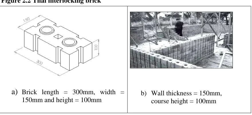
2.2.3 THAI INTERLOCK BRICKS
The Thai interlocking brick (Figure 2.2) with dimensions 300 x 150 x 100mm, was developed
in the early 1980s, by the Human Settlement Division of the Asian Institute of Technology
(HSD-AIT), Bangkok, in co-operation with Thai Institute of Scientific and Technical
Research (TISTR). This is an interlocking brick as defined in Section 2.2.1 (BS
6073-1:1981), although the developer calls it a block.
The Thai interlocking brick is produced using a modified CINVA-Ram manual press
developed in Colombia in 1956 (VITA 1975). Figure 2.2b shows a wall with vertical grooves
run through the full height that provide good keys for render. Vertical holes also run through
the full height of a wall, serving the following purposes:
•
They reduce weight•
They can house reinforcement or mortar to increase wall stability at chosen locations(corners, junctions, opening ends etc.)
Figure 2.2 Thai interlocking brick
a)
Brick length = 300mm, width =150mm and height = 100mm
b) Wall thickness = 150mm,
course height = 100mm
The grooves may however increase the amount of render required for internal plastering. The
holes in combination with the grooves may reduce the overall strength of a brick and hence
the strength of the wall built using these bricks. The locking mechanism is not well secured
as the knobs and depressions are too small (<5mm). The strength of such interlocks depend
on surface render, or on grout filled into vertical holes with additional reinforcements if need
arises.
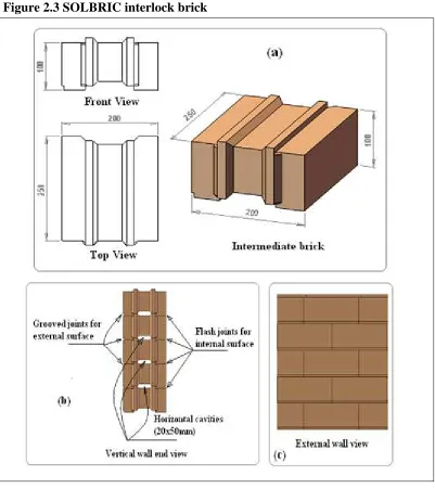
2.2.4 SOLBRIC SYSTEM FROM SOUTH AFRICA
The SOLBRIC system uses solid interlocking bricks (Figure 2.3a), formed by pressing on
their ends (the compacting stroke moves parallel to the longer side), with guided or controlled
width and height. In bricklaying, SOLBRICs are arranged at the normal bed surface (Figure
2.3c). The size of a SOLBRIC is 250 x 200 x 100mm. SOLBRIC provides small horizontal
reduces the thickness of required plaster mortar and the external pointed joint makes the
external appearance attractive. However this difference means that bricks may not be
[image:33.595.99.500.172.622.2]reversed (front to back).
Figure 2.3 SOLBRIC interlock brick
Although the SOLBRIC interlocking brick system seems to be easy to use, the shape of the
bricks and the parts made from the machine make it possible to build only the external walls
because there is no means of connecting partitions i.e. of making a tee or cross joints. The
interlocking are questionable due to the material used (soil stabilised with cement that is
brittle in nature).
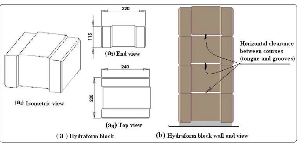
2.2.5 HYDRAFORM SYSTEM FROM SOUTH AFRICA
Hydraform is the simplest type of interlocking block (Figure 2.4) in shape, when interlocked
makes a tongue and grooved joint at the sides and top and bottom. Being free to slide along
the course horizontally, it can be pushed along to achieve tighter perpends (vertical joints)
[image:34.595.73.560.327.563.2]Figure 2.5.
Figure 2.4 Hydraform block
Hydraform block is moulded by pressing along its length from the ends, as for the SOLBRIC.
It is also a solid block, but slightly shorter, wider and thicker in size (240 x 220 x 115mm)
compression must be sufficient to allow a fresh block to withstand the squeezing forces
occurring when it is manually moved from machine to the curing area. A powerful (moulding
pressure 4MPa to 10MPa) and expensive motorised machine (Hydraform Manual, 2004) is
required to compact such a volume of soil. This can be compared to the cheaper manual
presses (with pressures under 2MPa) used to produce Bamba, Tanzanian and Thai types
(VITA 1975, Weinhuber 1995).
Figure 2.5 Typical Hydraform block-laying (diagram from Hydraform Manual 2004)
The Hydraform blocks require some 'shaving' and/or chopping (Figure 2.5) if two blocks
have to be laid perpendicular to each other (this could have been included in the production
process for time-saving at site). A half bat to cover the tongue/male (Figure 2.5) is also
required (Hydraform Manual 2004).
The longitudinal course joints (Figure2.4b) of the blocks have a clearance of 1-1.5mm
between the tongue/ridge and groove of the mating blocks. The reason behind this 'play' is
easy of longitudinal sliding, to simplify the block-laying in order to achieve tight perpends
(Figure 2.5). Apart from being stacked dry all other wall construction operations are as
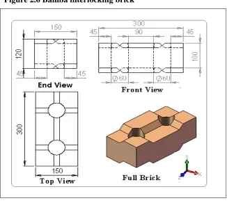
2.2.6 BAMBA SYSTEM FROM SOUTH AFRICA
The Bamba interlocking brick (Figure 2.6) is perforated, with protrusions and depressions.
The top and bottom faces of Bamba brick have negative symmetry: configurations opposite
to each other that allow them to fit (lock).
Figure 2.6, if the brick is rotated 180 degrees around its Z-axis, the bottom view will appear
as top view; this give the option of reversing to find a better orientation or position during
[image:36.595.135.461.217.509.2]brick-laying.
Figure 2.7 Available Bamba brick parts in the market
Bamba brick interlock better than all other types due to its shape, provided that high accuracy
is maintained. This accuracy depends on: proper soil selection, proper determination of
material mix (cement to soil and water to cement ratios), observation of good practice in
production and curing. Though the shape can yield a rigid structure, it is very difficult to
correct if bricks have defects. With these contradictory characteristics, the system is not fit
for use in developing countries because it requires accurate machinery and high skills in soil
selection to make sure that the production will be of one consistency. If every thing is perfect,
accuracy in size and shape due its complicated configuration, it consumes a lot of time
[image:38.595.76.520.141.446.2]shaving and shimming to compensate for brick irregularities.
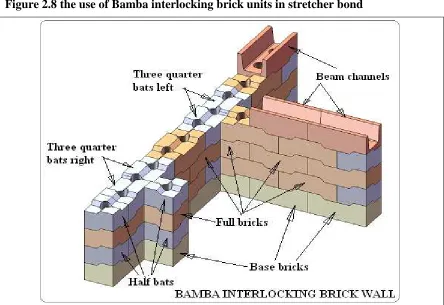
Figure 2.8 the use of Bamba interlocking brick units in stretcher bond
The occurrences of tee or cross joints alternate the use of three quarter bats from right to left, this does not depend on the distance from each joint, but the rotation of three quarter bats to meet at the centre of the joint that changes the orientation of the following brick
The author developed three-quarter bats Figure 2.7a and 2.7b (Kintingu 2003) for Bamba
interlocking brick to perform tee and cross joints. The available Bamba interlocking units
(Figures 2.6 and 2.7) can assemble wall as shown in Figure 2.8, but is restricted to half brick
wall and to just stretcher bond.
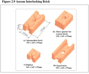
2.2.7 AURAM SYSTEM FROM INDIA
Figure 2.9 Auram Interlocking Brick
The Auram system reduces the number of three quarter bats required to just one due to shape
similarity, compared to the two required with Bamba interlocking brick (Figure 2.7). In this
type of interlock a three-quarter bat is used as a corner brick; this has flat ends, to avoid a
semi-circle notch appearing at the external surface of the wall. The Auram brick is more solid
and heavier at between 9Kg and 10Kg than the Thai and Bamba types at 7 to 8Kg. But the
locking mechanism depends entirely upon the bosses and depressions; this will require
experiments to examine the optimum height of male and depth of female features (<10mm) to
give enough wall punch-through strength.
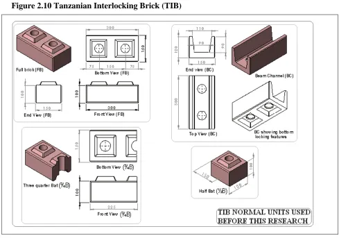
2.2.8 TANZANIAN INTERLOCK BRICK (TIB) SYSTEM
The TIB system Figure 2.10 was designed by the author after observing the weaknesses in the
Bamba system (Kintingu 2003). The new system (TIB), it was developed for appropriate
users. The machine, which is locally made and manually operated, is a modification of
[image:40.595.64.553.137.480.2]CINVA-Ram press machine (VITA 1975, Weinhuber 1995).
Figure 2.10 Tanzanian Interlocking Brick (TIB)
The author made important modifications to improve the interlock brick to suit Tanzanian
requirements. The size of the brick is 300 x 150 x 100mm, the same as that of Thai and
Bamba types respectively. The locking knobs and depression are two as for the Auram type,
but they are of pyramid shape with holes running through the centre of the knobs. The brick
is chamfered to the front and back edges, providing pointed horizontal and vertical wall
joints. This chamfer, gives a good key to the plaster if plastering is needed (the bricks from
The number of different brick parts was reduced to four (Figure 2.10), from the six of Bamba
(Figures 2.6 and 2.7) as follows: -
Tanzanian type (TIB) - Full brick, three quarter bat, half bat and beam channel.
Bamba system - Base brick, intermediate brick, left and right three quarter bats, half bat and
channel.
TIB (Figure 2.10), apart from its good locking mechanism, needs investigation of the shear
strength of its knobs and webs, to determine the optimum size that will provide sufficient
wall stability during construction. Also it seems that the vertical joint is not secured well, as
the brick ends meet at flat surfaces with no mechanical interlocking. It should have been
provided with a groove of at least 2.5mm radius at both brick ends, to create a void for a
minimum mortar to be placed (pumped) to fill the vertical gap. The TIB as other designs
available on market fails to satisfy some of the demands from the building industry, such as
the construction of:
• Various brick bonding joints,
• Piers (wider than half of brick length) attached into walls, which conventional
(mortared) brickwork can easily perform,
• Thicker walls (thickness more than half of brick length) and
• Different wall configurations (circular, polygonal, etc.).
Correcting these deficiencies of mortarless technology is a further work of this research
addressed in Chapter 4.
2.3 WALL PERFORMANCE FACTORS
A wall is the base/background to roofing, ceiling, doors and windows, beams, plaster,
Collins (1995), a wall is defined as a vertical structure made of stone, bricks or wood, with a
length and height much greater than its thickness, used to enclose a building and divide it into
cubes or rooms and support other elements/parts. The above-mentioned elements that are
supported by the wall comprise more than 50% of the total cost of the building. The wall
skeleton itself hardly accounts for 10% of the overall construction costs. We require the wall
to be fit for purpose and durable in order to secure all the elements fixed to it for the entire
life of the building. When we say a brick wall, we mean bricks arranged in certain pattern
(see bond as defined in Section 2.1) and joined with whatever material or means. According
to Hendry et al. (1997) the vertical compressive strength of a wall rises with only the square
root of the nominal crushing strength of a brick, or with the fourth or cube root of the mortar
cube strength. This is for walls that fail by crushing rather than by buckling. Also the
relationship of the wall strength to the thickness of mortar, shows that the lower the thickness
(down to one millimetre) the higher the wall strength. Spence and Cook (1983) show that
mortar does not contribute much to the compressive strength of a wall, even if the mortar
used is stronger in compression than brick. There is a need to find out if the mortar joint
thickness can be limited to maximum of three millimetres (with the aim of filling the gaps
after the bricks are laid). However wall strength does not only depend on the strength of the
basic elements (brick/block and mortar) alone, but also on:
• The shape (height, width, length and configuration) of the wall
• Brick design
• The way bricks are laid (the bond/pattern employed) (Hendry et al. 1997 and Spence
2.4 CHARACTERISTICS OF MORTARLESS WALLING
The worldwide housing shortage has stimulated a search for appropriate, easy, fast and
cost-effective ways of constructing walls. Among many technologies found to have promise is
mortarless technology (MT) using dry-stack interlocking bricks/blocks.
Although MT is quite new, it is booming around the world with diverse use in the building
industry, and it is now under study for space (extraterrestrial) applications. It comes in a
variety of forms, shapes, configurations, and sizes (Beall, 2000. Ramamurthy and Nambiar,
2004. Croft, 1993. Thanoon et al. 2004. Dyskin et al. 2005). Interlocking bricks are often
considered as ‘specials’ because of their need for unique moulds and their unsuitability for
the extrusion technique widely employed in brick-making. Interlocking bricks' are normally
produced using machines that guarantee good face texture (accurate and with appealing
surfaces that are smooth and even), thus giving the bricks an attractive finish that requires
little or no rendering, just joint sealing for protection from weather, achieving privacy and
avoiding health hazards. The reduction or even omission of joint mortar and plastering saves
construction time and materials.
The elimination of bedding mortar, although it reduces cost and accelerates the construction
process Ramamurthy and Nambiar, (2004), also induces structural weaknesses. Architectural
inflexibility (Chapter 4 subject matter) and structural instability are caused by geometric
imperfections in the brick-bed surfaces and any non-uniformity in the heights of adjacent
bricks Marzahn (1999). Moreover the complexity of some common ISSB configurations is a
further barrier to design and construction flexibility. All these imperfections cause difficulty
in keeping within maximum tolerable deviations from wall plumbness and straightness, and
may prevent construction of particular wall configurations. This requires further
2.5 SELF-ALIGNMENT AND INTERLOCKING
There are two major objectives of any dry-stack interlocking brick system. The first objective
is to be self-aligning (Gallegos 1988, Ramamurthy and Nambiar 2004. Thanoon et al. 2004.
Beall 2000. Jaafar et al. 2006). Features required for self-aligning interlocking bricks
includes:
• Fitting into each other without adjustments (cutting, shaving or shimming).
• Having distinct orientation features, so that if wrongly placed they will not fit and
therefore require either reversing or replacement for rectification.
• Fulfilling modular coordination requirements (Gilroy and Goffi 2001, Thanoon et al.
2004)
• Having tight tolerances (Gallegos 1988, Marzahn 1999, and Jaafar et al. 2006)
• Having few elements, each with its simple and unique overall shape, to simplify the
management during production and construction (i.e. unique shapes prevent
confusion between one and another). The word ‘element’ here denotes a member of a
brick set. For example a set might comprise three elements, namely full brick, half
and three-quarter brick.
The self-aligning (automatic stacking) of bricks will reduce the need for skilled labour
(Etherington, 1983. Gallegos, 1988), and enhance construction productivity.
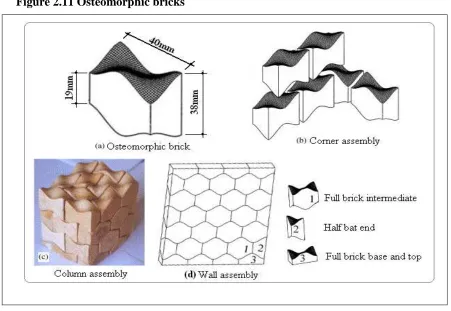
Most interlocking bricks (Section 2.2) lock by either having protrusion and depressions or
tongues and grooves, sometimes called male and female features. But the interlocking bricks
discussed by (Dyskin et al. 2005, Dyskin et al. 2003 and Estrin et al. 2002), are based on
are pressed together and achieve more surface contact. Such configurations restrict brick
movements both perpendicular to the wall surface and along the wall, so osteomorphic brick
[image:45.595.73.524.171.482.2]fall under category A in Table 2.1 (Figure 2.11b).
Figure 2.11 Osteomorphic bricks
The topological interlocking with non-planar surfaces (if sufficiently smooth) reduces stress
concentration. Being self-aligning and self-adjusting, osteomorphic bricks provide some
relaxation of the accuracy requirements of both brick production and wall assembly.
However the system being insensitive to the surface imperfection will lead to unevenness of
wall surfaces (Dyskin, et al. 2005) and so require a thicker layer of render mortar. Therefore
accuracy (smoothness and matching of the curvatures) requirements remain paramount as in
other MT configurations.
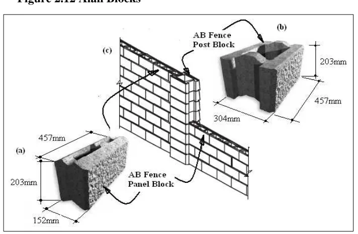
Another brick shape with similar characteristics to the osteomorphic brick is the Allan Block
AB blocks were tested by Shrive et al. 2003 who showed they have good potential for
tolerating both differential settlement and loading perpendicular to the wall surface (i.e. wind
forces). The panel block Figure 12a restricts perpendicular movement but allows horizontal
[image:46.595.103.459.202.435.2]sliding during block-laying (category B Table 2.1).
Figure 2.12 Alan Blocks
However the mechanism of self-aligning just discussed (osteomorphic brick and Alan block)
is not typical. Most of the MT systems that Least Developed Countries use (described in
Section 2.2) employ T&G or P&D interlocks, which are the focus of this research.
The second objective of a dry-stack interlocking brick system is to have an effective locking
means that allows dry-stacking to achieve straight, plumb and stable block-wall (Vasco
Costa, 1993) that can withstand different forces (horizontal shear and vertical bearing) under
loads applied (Gallegos 1988, Thanoon, et al. 2004) during and after construction. Table 2.1
the use of levelling and aligning instruments Gallegos (1988). The ability of IB to accurately
locate brick positions improves the bonding value of mortarless technology. The precision of
overlapping between courses improve masonry appearance and the distribution of loads Nash
(1991).
2.6 WALL ALIGNMENT ACCURACY
An accurately aligned masonry wall should be vertical to plumb, with truly straight and
horizontal (level) courses. The vertical joints (perpends) at alternating courses should be in
line and truly vertical throughout the wall height. The masonry panel face should have a flat
and true surface Nash (1983). Conventional masonry gives an acceptable range of vertical
deviation, which for a wall height up to 3m should not exceed 10mm (BS 5606:1990 Table 1
T.1.3).
All who have worked with interlocking bricks agree that in order to achieve good alignment,
the bricks should be geometrically accurate (Marzahn 1999, Beall 2000, Estrin et al. 2002,
Jaafar et al. 2006). However no critical analysis has been made of wall alignment. Research
so far has only addressed the important issue of performance in direct load-bearing of
interlocking dry-stacking systems.
Beall (2000) observed that the physical locking feature is a mechanism to improve the
accuracy of dry stacked masonry; it makes it easier to align the wall vertical and straight and
therefore speeds up construction Jaafar et al. (2006). However the relationship between wall
2.7 LOAD BEARING CAPACITY OF MORTARLESS WALL
A substantial amount of research has been performed to ascertain the behaviour of mortarless
walls under applied loads (Gazzola & Drysdale 1989, Drysdale & Gazzola 1991, Marzahn
1999, Marzahn and Konig 2002, Shrive et al. 2003, Jaafar et al. 2006,) both in-plane and
out-of-plane. Dry-stacked mortarless blocks have been tested under compressive, tensile and
shear loads, and their performance related to that of conventional (mortared) brickwork, for
which standards and codes for materials and structure quality are defined.
Gazzola & Drysdale (1989) tested dry-stacked interlocking hollow-block walls under
compressive, tensile and shear forces. Their results suggest MT masonry construction is
adequate for low rise buildings. Moreover any additional surface render enhances tensile and
shear strengths and gives some improvement in compressive strength.
In further work, Drysdale & Gazzola (1991) studied the strength properties and load-bearing
capacity of grouted dry-stacked mortarless hollow-block walls.
The blocks used to build test prisms had an average material compressive strength of 30.4
MPa. The test results of grouted prisms (Figure 2.13) attained an average flexural tensile
strength of 1.7MPa. This is over six times the minimum value allowable in the North
Figure 2.13 Test brick prism
The standard prism to ASTM C90-75 consists of one brick width, various courses ranging between 1.5 and 5 times the brick height, and one stretcher (Jaafar et al. 2006, Drysdale and Gazzola 1991)
The British Standards (BS 5628-1:2005 Table 3) require blocks with compressive strength
above 17.5MPa, to be designed for a hollow-block wall to withstand average characteristic
flexural strength of0.25MPa. However the test result attained by Drysdale and Gazzola will
produce a structure with a 6.8 factor of safety, which agrees with the North American
Building Codes. This can be summarised as follows
Material classifications
Drysdale and Gazzola test results
British Standard (BS) requirements (for conventional wall)
Strength Factor of safety
Block-compressive
strength (MPa) 30.4 >17.5 1.7
Prism-flexural
strength (MPa) 1.7
0.25
(hollow-block wall) 6.8
Jaafar et al. (2006) also tested interlocking mortarless hollow-block panels under
compressive loads. He used blocks with an average compressive strength of 15.2MPa. The
wall panels’ compressive strength was 5.9MPa. The correlation between strength of