Designing a dike using a
semi-probabilistic design
method
Bachelor Thesis
Ellen Daamen
1 July 2016
This is the bachelor thesis of Ellen Daamen, s1485873.
The bachelor thesis is the final assessment in order to complete the bachelor study Civil Engineering of the University of Twente. During this bachelor thesis the student has to show that she has sufficient substantive knowledge and can work and report systematically. The bachelor thesis is performed at an external company in order to see if the student can put the gained knowledge into practice. The research for the bachelor thesis is performed at Witteveen+Bos in Deventer.
The research and the report of the bachelor thesis are performed under guidance of;
2
Preface
With the bachelor thesis the bachelor program of civil engineering will be completed. For the bachelor thesis there was a 10-week internship at an external company. I performed my bachelor thesis at Witteveen+Bos in Deventer at the department of deltas, coastal areas and rivers.
For my bachelor thesis I was looking for a practical research in which I put my knowledge into practice. In my application letter I wrote that I was looking for a research with respect to rivers and dikes, that I used to be around the Lower Rhine in Oosterbeek in my childhood and that I was there often during the weekends and in holidays at our sailboat. When I heard that Witteveen+Bos had a project for me about KEMA Laboratories that was located in Arnhem near the Lower Rhine, I was very excited. The location of the subject of my thesis was located two kilometers upstream of the location where I spend most of my childhood holidays. I was familiar with the research location of my thesis so it was for me much easier to do the research and relate to its surroundings. For me the bachelor thesis was a very educational experience. I learned a lot about the new programs, the design methods for dikes and how it worked at an engineering agency.
During my thesis I was guided by Ir. Joost Lansink of Witteveen+Bos and MSc. John Damen of the University of Twente. I want to thank them for their help and feedback during my thesis. I also want to thank my colleagues at Witteveen+Bos, Reza Hussaini and Joost Noordermeer, who helped me during my thesis and could always make time to help and explain.
3
Table of contents
PREFACE 2
ABSTRACT 5
1. INTRODUCTION 6
1.1 Current situation 6
1.2 Problem definition 6
1.3 Context 7
1.4 Research aim 8
1.5 Limits and boundaries of the research 8
1.6 Research method and approach 9
1.7 Reading guide 11
2. REQUIREMENTS AND BOUNDARY CONDITIONS 12
2.1 Requirements and demands of KEMA Laboratories 12
2.2 Hydraulic boundary conditions 12
2.3 Geometric boundary conditions 14
2.4 Geotechnical boundary conditions 16
2.5 Geo-hydrological boundary conditions 18
3. DESIGN CALCULATIONS AND OUTPUT 19
3.1 Crest height 19
3.2 Piping 20
3.3 Macro stability 22
4. DIKE DESIGNS 26
4.1 Dike options 26
4.2 Cost calculation 28
4
5.1 Criteria 29
5.2 Analysis of dike designs 29
5.3 Multi-criteria analysis 30
6. DISCUSSION 31
7. CONCLUSION 31
8. RECOMMENDATIONS 32
9. REFERENCE LIST 33
ANNEXES 35
A. HYDRAULIC BOUNDARY CONDITIONS 35
1. Location 35
2. Simulation of water levels 36
3. Simulation of hydraulic load (‘Hydraulisch belasting niveau’) 39
B. GEOMETRIC BOUNDARY CONDITIONS 41
C. GEOTECHNICAL BOUNDARY CONDITIONS 42
1. Soil borings at location KEMA Laboratories 42
2. Thickness of aquifer 43
3. Table 2b. NEN 1997-1 +C 44
D. DESIGN CALCULATIONS 45
1. Calculations height 45
2. Calculations piping 46
3. Calculations macro stability 54
E. COST CALCULATION 67
1. Determining required quantities 67
5
Abstract
KEMA Laboratories is located near the Lower Rhine in Arnhem. For a future expansion all risks have been identified. KEMA Laboratories is located near the Lower Rhine, outside the primary flood defenses. One of the potential risks of the area around KEMA Laboratories is flooding. In order to make sure that the area around KEMA Laboratories does not get flooded, a dike will be designed for this location. Witteveen+Bos created in an earlier research a temporary solution for this problem. They created an emergency plan with big bags and sand bags that can be placed if high water is expected. The emergency plan that Witteveen+Bos created is based on the former philosophy of probability of exceedance. The emergency plan also has the disadvantages that it is a temporary solution and that it has to be practiced regularly. For the bachelor thesis the option is researched to replace this temporary solution with a structural solution. A dike is designed using a semi-probabilistic design method, which is the most recent method for the designing and testing of flood defenses. The semi-probabilistic design method is still in development, but the government aims to implement this new method in 2017. A probabilistic design approach aims to determine the probability of flooding and to judge its acceptability in terms of the consequences. The dike designs in this research are made according to a semi-probabilistic design method. It is not possible yet to make a dike design with a fully probabilistic design method.
6
1.
Introduction
1.1
Current situation
KEMA Laboratories is located in Arnhem near the Lower Rhine. The KEMA High-Power Laboratory in Arnhem provides a short-circuit, switching and mechanical testing and certification to utilities and equipment manufacturers worldwide (DNV GL, 2016). The laboratory is part of the DNV GL group that is a worldwide classification society in particular for the energy, maritime, oil & gas industry. DNV GL will build an expansion of the High-Power Laboratory in Arnhem. As is shown in Figure 1 KEMA Laboratories is located near the Lower Rhine. The ground level at the location is between 13.90m +NAP and 14.15m +NAP. KEMA Laboratories is located at an area outside the dikes near kilometer marker 886. The area of the KEMA is not located within a dike ring. It is situated across from dike ring 43-3 and in the extension of dike ring 47-1, as is shown in Figure 2. The location is outside the primary flood defenses, but the laboratories are located on formal high ground. For the expansion of KEMA Laboratories all potential risks have been identified. Since KEMA Laboratories is located near the Lower Rhine, there is a risk of flooding. In an earlier research Witteveen+Bos created an emergency plan for this location with big bags and sand bags that can be placed at the location of KEMA Laboratories if a high water level is predicted.
Figure 1: Location of KEMA Laboratories (Bing Maps, 2016) Figure 2: Location of KEMA Laboratories with respect to dike rings (Deltacommissaris, 2014)
1.2
Problem definition
7
1.3
Context
The Netherlands has a land area of 42.000m2 and about 17 million inhabitants. About 50 per cent of the Netherlands is below sea level. This land is protected from flooding by dunes and dikes that stands between the land and the water. Although the east side of the Netherlands is located on higher ground, much of this land is protected from river floods by dikes. Safety from flooding is provided by 53 dike rings, which protect the land areas behind the dikes. (Walker, et al., 1994)
History of dike design
In the middle ages dikes were designed at the highest known storm plus one meter additional freeboard. This practice was not possible anymore since the construction of the Afsluitdijk, because there was no data available about the storms at this location. After the flood disaster in 1953, storm surge levels were approached statistically and extrapolated storm surge levels were then used for dike designs. Since the 1980s engineers started to use probabilistic methods for dike designs (Vrijling, 2000).
In the Netherlands the design of dikes and other water retaining structures were based on an acceptable probability of overtopping. The designs were based on an average return period of exceeding a certain water height at each dike section. There are four safety classes for the acceptable average return periods of 1.250, 2.000, 4.000 and 10.000 years. This method for designing dikes stems from a time when only the water levels were considered to be a statistical quantity and overtopping of the dike was considered the most dangerous failure mechanism (Van Manen & Brinkhuis, 2005).
Flood risk
Since the 1980s the awareness grew that the probability of exceedance of the design water level is not a good predictor of the probability of flooding. Some parts of the dike may already be critically loaded before the design water level is reached. Dikes can also fail because of macro instability, in which a part of the dike slides off, or piping, when water can flow through the sand layer under the dike and causes the dike to fail. Also the length of the dike ring has influence on the on the flood risk of the dike. A single weak spot determines the actual safety of the dike, since a chain is as strong as the weakest link (Vrijling, 2000). Because of the shortcomings of the old design method, the Dutch Government wants to change the acceptable maximum frequencies of overtopping to a new system that sets limits to a maximum allowed risk. Risk is in this case defined as the probability multiplied by the consequences, where the consequences consist of material damage, victims, environmental and cultural damage (Van Manen & Brinkhuis, 2005).
Probabilistic design method
The probabilistic design approach aims to determine the probability of flooding and to judge its acceptability in terms of the consequences. The modern probabilistic approach aims to give protection to areas with high risks. (Vrijling, 2000). The dike designs in this research are made according to a semi-probabilistic design method. This is the most recent method for the designing and testing of water retaining structures. It is not possible yet to make a dike design with a fully probabilistic design method. The difference between a semi-probabilistic method and a probabilistic method is that a semi-probabilistic design method works with designs values for the loads on the dike and the strength of the dike. These design values consist of a strength parameter and a safety factor. A probabilistic design approach is based on the probability that the load on the dike (S) is bigger than the strength of the dike (R) is lower than a certain requirement for the failure probability (PT). This can also be displayed
8
1.4
Research aim
The research aim of the bachelor thesis is to design a dike for KEMA Laboratories near the Lower Rhine by using a semi-probabilistic design method. A semi-probabilistic method is the most recent method to test and design dikes. The new method is presented in the “Deltaprogramma 2015”. The government aims to complete the new norms on 1-1-2017 so that from that moment designs and tests will be made according to the new standards for flooding. For the bachelor thesis the main research question that will be answered is: What dike design scores best on the given requirements and boundary conditions using a semi-probabilistic design method?
To answer the main research question the following sub questions will be answered:
What are the requirements and boundary conditions at the location?
What dike designs are feasible at the location?
What are the costs of the designs?
What design scores best on the given the boundary conditions, requirements and wishes?
1.5
Limits and boundaries of the research
For the research the following limits and boundaries are established:
Since the location of KEMA Laboratories is not located on a dike ring, it is assumed that it is located on dike ring 47-1. The maximum accepted chance of failure and the new norm for exceedance probability of dike ring 47-1 will be used as an input for the design. So the maximum fail probability will not be computed for the specific area, but will be taken from the data of dike ring 47-1. The location of KEMA Laboratories is close to dike ring 47-1. If the new dike at the location breaches this will not have impact on dike ring 47-1.
The designs will be made on the basis of the boundary conditions for the requirements of height, stability and piping. The requirements for the failure mechanisms micro stability and stability of the foreland will not be taken into account for the designs, since these failure mechanisms are determined completely deterministic (Ministry of
Infrastructure and the Environment, 2015).
The dike design will be based on a two dike sections, which means that the required properties for two sections will be calculated. These two dike sections will be calculated and will be seen as normative for the dike.
The costs of the designs will be determined with the methods and programs that are used by the department for cost calculation of Witteveen+Bos. There will be no adaptations in this cost calculation.
9
1.6
Research method and approach
Research method
The dike is designed using a semi-probabilistic design method. The research is done according to method that is described in “Handreiking ontwerpen met Overstromingskansen” (Ministry of Infrastructure and the Environment, 2015). This report gives an addition to the all existing guidelines for the design and calculations for dikes. Besides this manual the following technical reports are used for the designs of the dike:
Achtergrond Rapport Ontwerpinstrumentarium 2014 (Ministry of Infrastructure and the Environment, 2015)
Technisch Rapport Grondmechanisch Schematiseren bij Dijken (expertisenetwerk waterveiligheid, 2012)
Technisch Rapport Klei voor Dijken (Technische Adviescommissie voor de Waterkeringen, 1996)
Technisch Rapport Ontwerpbelastingen voor het Rivierengebied (Ministry of Transport, Public Works and Water Management, 2007)
Technisch Rapport Waterkerende Grondconstructies (Technische Adviescommissie voor de Waterkering, 2001)
Technisch Rapport Waterspanningen bij Dijken (Technische Adviescommissie voor de Waterkeringen, 2004)
Technisch Rapport Zandmeevoerende Wellen (Technische Adviescommissie voor de Waterkeringen, 1999)
Werkwijze bepaling Hydraulische randvoorwaarden (Deltares, 2015) Approach
The research for the dike has been conducted as follows: Firstly, the current situation is researched, a problem definition is defined and a literature research has been conducted. Secondly, the boundary conditions are determined. There are five categories for the boundary conditions: requirements and wishes of KEMA Laboratories, hydraulic boundary conditions, geometric boundary conditions, geotechnical boundary conditions and geo-hydrological boundary conditions. Thirdly, the design calculations are made for height, piping and macro stability. If all the design calculations are made, then the properties for the dike are determined. Fourthly, with the properties of the dike the dike design can be made. In this phase also the costs of the designs options are calculated. Fifthly, a multi-criteria analysis is used to choose the optimal dike design for KEMA Laboratories. At last, the discussion, conclusion and recommendation are formulated. The approach is also shown schematically in Figure 3.
Figure 3: Research approach Research planning
• Current situation • Problem definition • Literature research • Research aim
Determing boundary conditions
• Wishes and requirements of KEMA Laboratories • Hydraulic boundary
conditions • Geometric boundary
conditions
• Geotechnical boundary conditions • Geo-Hydrological boundary conditions Design calculations • Height • Piping/heave • Macro stability
Designs
• Establishing designs • Cost calculation
Multi-criteria analysis
• Criteria • Comparing designs
Conclusion and recommendation
10
Used models
For the research and the design of the dike various models are used.
Model for simulation the water levels and the hydraulic load at KEMA Laboratories
The water levels and the hydraulic load are simulated in the program “Hydra Zoet”. “Hydra Zoet” is based on a probabilistic model that compares different scenarios for wind and water and calculates the scenario which has the highest probability of occurrence. This model is used to determine the water levels and wave properties by different return periods. The data that is produced by this model is later used for the calculations of height, piping and macro stability.
Model for calculating the required height
The required height of the dike is determined in PCOverslag. The model determines the minimum height of a dike for a certain allowed overtopping flow. The calculations of PCOverslag are based on empirical formulas for overtopping discharge. The empirical formulas are based on lab and field research that determine the wave overtopping given the slope of the dike, the wave direction, the wave height and roughness parameters. The model is based on the technical report “Technisch Rapport Golfoploop en Golfoverslag bij Dijken”.
Model for piping
The calculations for piping are done with the formulas for piping of Sellmeijer. De formulas of Sellmeijer are described in the technical report “Technisch Rapport Zandmeevoerende Wellen”. The calculations are based on empirical formulas. The used formulas of Sellmeijer can be found in Annex C2.
Model for macro stability
The model of Bishop is used for the calculations of macro stability. In the program D-Geostability the different dikes are modelled. D-D-Geostability is a program in which the soil structures and geometry of the dike can be drawn. After adding the characteristics of the soil, the program can calculate the safety factor of the macro stability of the dike. Macro stability in this research is calculated based on the equations of the model of Bishop.
Model for phreatic water levels
Phreatic water levels in the dike are determined for the calculations of macro stability. In absence of a local geo-hydrological model for phreatic lines, the calculation methods described in the technical report “Technisch Rapport Waterspanningen bij Dijken” (Technische Adviescommissie voor de Waterkeringen, 2004) are used to determine the water levels in the dike. The phreatic lines and the used model are further explained in paragraph 2.5 Geo-hydrological boundary conditions.
Model for cost calculation
11
1.7
Reading guide
The structure of the report is as follows. In the main report all conclusions and a summary of the results can be found. More information about the data or the calculations can be found in the corresponding Annex. In every chapter there will be a reference to the Annex with additional information.
In Chapter 2 all boundary conditions can be found that are established for the research. There are five types of boundary conditions taken into account: requirements and demands of KEMA Laboratories, hydraulic boundary conditions, geometric boundary conditions, geotechnical boundary conditions and geo-hydrological boundary conditions.
In Chapter 3 an overview of the calculations for height, piping and macro stability can be found. In the chapter there will be references to the corresponding annexes, in which the calculations are more described and explained.
In Chapter 4 a description of the feasible designs can be found. The dike designs are defined and a cost calculation is done to determine the construction costs of the dike designs. In Chapter 5 a multi-criteria analysis is conducted on the feasible designs. In this chapter the criteria, an analysis of the dike designs and the multi-criteria analysis can be found.
12
2.
Requirements and boundary conditions
The designs for the dikes will be made based on the limits and boundaries of the locations. Before the designs are made, the requirements and boundary conditions are established. The requirements and boundary conditions are divided into five categories: the wishes and requirements of KEMA Laboratories, the hydraulic boundary conditions, the geometric boundary conditions, geotechnical boundary conditions and the geo-hydrological boundary conditions.
2.1
Requirements and demands of KEMA Laboratories
In order to make the designs for the dike, the requirements and wishes of KEMA Laboratories have to be established. The following requirements and wishes of KEMA Laboratories have been taken into account for the designs:
The dike should have a crest width of 4 meters, in order to accommodate maintenance vehicles like mowers.
The dike has to be a green dike, which means that there will be a grass revetment on the dike for erosion protection and spatial value.
KEMA Laboratories demands two options for the dike location. They demand an option on the foreland on the dike and an option on the terrain close to the laboratories. The underlying assumption is that the option on the foreland is more expensive, but has less impact on the terrain of KEMA Laboratories and the current infrastructure.
Maintenance vehicles, like mowers, have to be able to ride on the dike. This should be taken into account in the temporary load on the dike and in the calculations of macro stability of the inner and outer slope of the dike.
KEMA Laboratories prefers not to lose too much of the hardened surface of the area around the laboratories and demands that all buildings will be retained.
2.2
Hydraulic boundary conditions
The hydraulic boundary conditions are determined with the “Werkwijze bepaling hydraulische ontwerprandvoorwaarden” (Deltares, 2015). The design water levels and the wave conditions have been determined in order to form the hydraulic boundary conditions. The design water levels and the wave conditions are determined in ‘Hydra Zoet’. Hydra Zoet is a probabilistic model that combines wind and discharge scenarios. It is developed by Rijkwaterstaat and it can be used for testing and determining hydraulic boundary conditions of water-retaining structures near fresh water with a semi-probabilistic method. All calculations for the hydraulic boundary conditions can be found in Annex A.
Design water levels
13
1,8 km upstream KEMA Laboratories is used for the simulation of the water levels. The simulated water levels are corrected with an uncertainty addition of +0,30m and a correction for the slope of the river with -0,18 m. The simulated water levels, the corrected water levels and their return periods are shown in Table 1.
Table 1: Corrected water levels at KEMA Laboratories
Return period (years) Simulated water levels (m +NAP)
Corrected water level (m +NAP)
1.000 13,76 13,88
2.000 13,86 13,98
4.000 13,96 14,08
10.000 14,08 14,20
20.000 14,18 14,30
In this research it is assumed that KEMA Laboratories is located on dike ring 47-1. The norm for the allowed failure probability of height for this dike ring is 1/4.170 years for this dike ring (Ministry of Infrastructure and the Environment, 2015). So the simulated water level of 14,08m that occurs with a return period of 4.000 years is used as the design water level for the calculation of the required height.
Wave conditions
The wave conditions are determined with “Hydra Zoet”. Since the location of KEMA Laboratories is near water at both sides, wave conditions are determined for both locations. Two locations are specified for the determination of the hydraulic boundary conditions, which are location west and location south. This is shown in Figure 4. Hydra Zoet is used to calculate the wave heights and the hydraulic loads.
Figure 4: Location west and south at KEMA Laboratories
14
Table 2: Significant wave height (Hs) and spectral wave period (Tm-1) for locations south and west
Location Hs (m) Tm-1 (s)
South 0,53 2,5
West 0,66 2,8
Ground level at KEMA Laboratories
The ground levels at KEMA Laboratories are established with data from the height data of AHN (“Actueel Hoogte Bestand”) and Bingmaps in QGis. The heights at the location are shown in Figure 5. The ground levels are used in the calculations for piping and macro stability.
Figure 5: Height at locations in m +NAP (Actueel Hoogtebestand Nederland, 2014)
Allowed overtopping flow
The allowed overtopping flow for the designs is 0,1 L/s/m. Since an overtopping flow at this location is not desired, the lowest possible overtopping flow is used for the calculations (Ministry of Infrastructure and the Environment, 2015). With this overtopping discharge there are no restrictions for the revetment on the inner slope of the dike. The allowed overtopping flow is used in the calculations for the required height.
2.3
Geometric boundary conditions
Current geometry
15
Figure 6: Current geometry of the foreland on location south (Actueel Hoogtebestand Nederland, 2014)
Figure 7: Current geometry of foreland on location west (Actueel Hoogtebestand Nederland, 2014)
Crest width
A requirement of KEMA Laboratories is that the dike has a crest width of at least 4 m, so that maintenance vehicles are able to ride on the dike.
Location of the dike
The dike options will be designed for two locations for the dike. The dike will either be on the foreland of KEMA Laboratories or on the terrain of KEMA Laboratories. The two locations are shown in Figure 8 and Figure 9.
Figure 8: Dike design on the terrain of KEMA Laboratories
16
2.4
Geotechnical boundary conditions
Soil structure
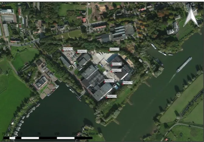
At the location of KEMA Laboratories eight borings have been performed. The locations of the eight borings are shown in Figure 10. There are no borings performed at the exact location of the dikes so an estimation of the soil structure is made. The data from the eight borings are compared, but it was not possible to deduce a general soil structure of the area around KEMA Laboratories. So for the dike designs the data of boring B40A0374 and B40A0179 are used, since these borings are closest to the location of the new dike.
Figure 10: Location soil borings at the location of KEMA Laboratories
[image:17.595.109.445.193.427.2]Different borings are used for the calculations of piping and macro stability. The data from boring B40A0179 (shown in Table 3) is used for the calculations of macro stability and the data from boring B40A0374 (shown in Table 4) is used for the calculations of uplifting and piping. This is the most conservative assumption, since boring B40A0179 has a thicker layer of clay. This means that this soil is more sensitive for macro stability because clay has lower strength characteristics than sand. Since there is no sample from the top layer of the ground it is assumed for the calculations that this is clay, since this is the soil that has the lowest strength characteristics.
Table 3: Soil structure at location B40A0179
From [m +NAP] To [m +NAP] Soil type
12,00 11,00 No sample
11,00 8,00 Clay, sandy
8,00 2,00 Sand, gravelly
2,00 -1,00 Sand
-1,00 -3,00 Sand, gravelly
17
Table 4: Soil structure at location B40A0374
From [m +NAP] To [m +NAP] Soil type
13,20 12,90 Sand
12,90 12,44 Sand, gravelly
12,44 10,94 Clay
10,94 10,65 Sand
10,65 10,10 Sand, clayey
10,10 9,60 Sand, gravelly
9,60 7,94 Gravel
7,94 3,48 Sand, gravelly
3,48 3,20 Sand
3,20 3,00 Gravel
The two used borings only have data up to 3m +NAP. Since the failure mechanism piping occurs in the aquifer under de covering clay layer it is necessary to determine the thickness of the aquifer. There is one deeper boring performed at the location of KEMA Laboratories (up to a depth of -90 m +NAP). This data is used in combination with a section of the soil structure of the area to estimate the thickness of the aquifer on 21m. The data from the borings and explanations can be found in Annex C1 and Annex C2.
Material of the dike
There are two options for the materials of the dike design. The first option is a sand dike with a top layer of clay. The second option is dike completely made out of clay. The material of the dike has influence on the phreatic water levels in the dike and depends on the maximum allowed overtopping flow.
Revetment
A requirement of KEMA Laboratories is that the dike has to be a green dike. This means that the dike has a revetment of grass. With the chosen maximum allowed overtopping flow of 0,1 L/s/m there are no requirements for the revetment of the dike.
Ground characteristics
The ground characteristics are determined with the data Table 2b from NEN-1997-1 +C1 for the characteristic values of the soil. This table can also be found in Annex C3. The ground characteristics are used in the calculations for piping. The characteristics are shown in Table 5 and Table 6.
Table 5: Characteristics of the clay and sand
Characteristic Symbol Clay Sand
Volumetric weight saturated γsat 17 kN/m3 20 kN/m3
Volumetric weight dry γdry 17 kN/m3 18 kN/m3
Cohesion c 5 kPa 0 kPa
Angle of internal friction φ 17,5° 32,5°
Table 6: Additional characteristics of sand
Characteristic Symbol Value
70-percentile value of the grain distribution d70 2,10*10-4
Angle of internal friction θ 37°
Permeability k 2,85*10-4 m/s
18
2.5
Geo-hydrological boundary conditions
Phreatic water levels
The phreatic lines in the dikes are calculated for the calculations of macro stability of the inner and outer slope. In every design there are two phreatic lines. The first line is the line that is calculated with the technical report “Technisch Rapport Waterspanningen bij dijken” (Technische Adviescommissie voor de Waterkeringen, 2004). The second phreatic line is the water level at the normative high water level.
Phreatic water levels for macro stability of the inner slope
Two phreatic lines are schematized for the calculations of macro stability of the inner slope. The first phreatic line is calculated with the formulas from “Technisch Rapport Waterspanningen bij dijken”. The phreatic line in a clay dike is different than a phreatic line in a sand dike with clay cover. An example from the phreatic lines in sand and clay dikes is shown in Figure 11 and Figure 12. The second phreatic line is the line at the level at normative high water. The maximum accepted chance of failure mechanism macro instability is 1/1.000 years (Ministry of Infrastructure and the Environment, 2015). The normative high water level with a return period of 1.000 years is 13,88m +NAP. This water level is used for the calculations for the macro stability of the inner slope.
Figure 11: Phreatic line in a clay dike (Technische Adviescommissie voor de Waterkeringen, 2004)
Figure 12: Phreatic line in a sand dike with clay cover (Technische Adviescommissie voor de Waterkeringen, 2004)
Phreatic water levels for macro stability of the outer slope
19
3.
Design calculations and output
In this chapter a summary of the design calculations for height, piping and macro stability can be found. The results from the calculations determine the properties of the dike designs. At the end of this chapter the required properties for the dike designs are clear and the dike designs can be made. All design calculations can be found in the Annex. In every subparagraph there will be a reference to the corresponding Annex.
3.1
Crest height
The required crest height is calculated for the west and the south location. The two dikes are calculated with a 1:3-dike profile. For the calculation of height the hydraulic load on the dike is simulated in “Hydra Zoet”. The requirement for the failure mechanism height is 1/4.170 year (Ministry of Infrastructure and the Environment, 2015). So the used design water level from the simulated hydraulic load on the dike has a return period of 4.000 years. The input that is used for the calculations is shown in Table 7. The water level that occurs with a return period of 4.000 years is 14,08m +NAP. There is no data available about the normative storm duration, so the choice is made to estimate the normative storm duration on the maximum value of 20.000 s (±5,5 hours).
Table 7: Input PCOverslag for determination of required height at location south and west
Input Symbol Unit Data location
south
Data location west
Significant wave height Hmo Meters 0,53 m 0,66 m
Wave direction β Degrees 73° 24°
The spectral wave period Tm-1 Seconds 2,5 s 2,8 s
Water level SWL Meters 14,075 m 14,075 m
Normative storm duration Tsm Seconds 20000 s 20000 s
Average wave period Tm Seconds 2,0 s 2,0 s
*Angle between dike normal and wave direction with respect to North
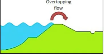
[image:20.595.108.291.553.650.2]With this input the required crest height is determined with PCOverslag. PCOverslag calculates the required the required height for the dike for four different overtopping flows. The allowed overtopping flow is the amount of water that is allowed to flow over the dike. In Figure 13 an explanation of overtopping flow is shown. The choice is made for the designs for a maximum overtopping flow of 0,1 L/s/m. Since an overtopping flow is not desired at the location, the lowest possible overtopping flow of 0,1 L/s/m is used for the calculations.
Figure 13: Overtopping flow over the dike
Required crest height
20
the wave run up is higher and that leads to a higher required dike. All calculations and extra explanations can be found in Annex D1.
Table 8: Required crest height for profile 1:3
Location Height (m +NAP)
South 15,1
West 15,7
3.2
Piping
By the failure mechanism piping, the dike fails because water and soil particles can flow through or under the dike. The failure mechanism piping is shown in Figure 14. In order to make sure that the dike will not fail because of piping the designs have to be checked for piping. Piping can only occur if uplifting can happen at the location. By uplifting the water pressure from below is higher than the ground pressure, which allows water to push the ground away and flow under the dike. If uplifting is possible, this does not mean that the dike will fail. But the dike will need a minimum width, in order to prevent the soil particles from flowing through the dike, because this will lead to a failure of the dike. At first the dike locations where piping can occur are checked for uplifting. If uplifting can occur then the required seepage length is determined. The required seepage length determines a property for the dike designs.
Figure 14: The failure mechanism piping (Technische Adviescommissie voor de Waterkeringen, 1999).
Soil structure of boring B40A0374 is used for the calculations of piping (shown in Table 4). This is a conservative assumption, since the soil structure of this boring has a thinner layer of clay; the ground is more sensitive for uplifting. Piping and uplifting are calculated with the formulas described in ‘Handreiking ontwerpen met overstromingskansen” (Ministry of Infrastructure and the Environment, 2015) and the formulas of Sellmeijer (Technische Adviescommissie voor de Waterkeringen, 1999). According to “Handreiking ontwerpen met overstromingskansen” the design water level for piping is the water level with an exceedance probability similar to the maximum accepted chance of failure (Ministry of Infrastructure and the Environment, 2015). The maximum accepted chance of failure mechanism piping is 1/1.000 years (Ministry of Infrastructure and the Environment, 2015). The simulated water level that occurs with a return period of 1.000 years is 13,88m +NAP. This design water level will be used for the calculations of uplifting and piping. All calculations for piping and uplifting can be found in Annex D2.
Uplifting
21
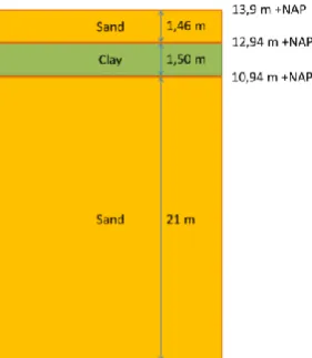
[image:22.595.328.469.76.238.2]Figure 15: Soil structure for calculations for uplifting on the foreland
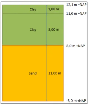
Figure 16: Soil structure for calculations for uplifting on terrain of KEMA Laboratories
Calculations uplifting
Uplifting is calculated with the formulas that are described in “Handreiking ontwerpen met overstromingskansen” (Ministry of Infrastructure and the Environment, 2015). The formula calculates the ratio between the ground pressure and the water pressure. If 𝑔𝑟𝑜𝑢𝑛𝑑 𝑝𝑟𝑒𝑠𝑠𝑢𝑟𝑒
[image:22.595.114.249.77.240.2]𝑤𝑎𝑡𝑒𝑟 𝑝𝑟𝑒𝑠𝑠𝑢𝑟𝑒 ≥ 1,0 , then uplifting cannot occur at the location. The results from the calculations for piping and uplifting are shown in Table 9. All calculations for uplifting can be found in Annex D2 .
Table 9: Results calculations uplifting
Location Ground pressure Water pressure 𝐠𝐫𝐨𝐮𝐧𝐝 𝐩𝐫𝐞𝐬𝐬𝐮𝐫𝐞
𝐰𝐚𝐭𝐞𝐫 𝐩𝐫𝐞𝐬𝐬𝐮𝐫𝐞
Does uplifting occur?
Foreland 7,3 kN/m2 30,5 kN/m2 0,24 Yes
Terrain of KEMA Laboratories
22,6 kN/m2 12,5 kN/m2 1,81 No
So in conclusion, piping on the foreland can occur. Uplifting is possible at the foreland and this means that piping is a relevant failure mechanism. The required seepage length needs to be calculated. Piping through a deeper sand layer cannot occur at the terrain of KEMA Laboratories.
Calculations piping
Since uplifting is possible on the foreland the required seepage length is calculated. The seepage length is determined with the formulas of Sellmeijer, which are described in the technical report “Technisch Rapport Zandmeevoerende Wellen” (Technische Adviescommissie voor de Waterkeringen, 1999).
Factor of schematization
In order to determine the seepage length first the factor of schematization is determined. This factor accounts for uncertainties in the soil structure, water pressure and other input parameters. This factor is one of the safety factors that are in the formula of Sellmeijer. The factor of schematization γb is estimated with the method described in the technical report
22
1. The ground level on the inside of the dike is 0,3m lower 2. The layer of clay is 0,5m thinner
3. The aquifer is 35m thick instead of 21m 4. Locally the layer of clay is missing
With this method the factor of schematization is estimated on 1,13. The factor is schematization is calculated for the dike on the foreland on location south. This is the only location where piping can occur. Piping on the west location is not possible since the design is partly located on the terrain of KEMA Laboratories and there is no gravity flow. All calculations for the scenarios and the determination of the factor of schematization can be found in Annex D2.
Strength factor
The other safety factor is the strength factor γmp. This factor depends on the reliability
requirement which is given in “Handreiking ontwerpen met overstromingskansen”. The γmp
is 1,20 for dike ring 47-1 (Ministry of Infrastructure and the Environment, 2015). Seepage length
The calculated seepage length is calculated with the formula of Sellmeijer, which is described in the technical report “Technisch Rapport Zandmeevoerende Wellen” (Technische Adviescommissie voor de Waterkeringen, 1999). The required seepage length is determined for the dike design on the foreland of KEMA Laboratories, since this is the only location where piping can occur. The calculated seepage length with the strength factor γmp of 1,20
and a schematization factor γb of 1,13 gives a seepage length of 31,0 m. The distance
between the entrance point of the water and the outlet point has to be more than 31 meter apart to prevent piping.
3.3
Macro stability
Due the failure mechanism of the macro stability the dike and the ground under the dike slides away, which causes the dike to fail. The macro instability of the inner slope is shown in Figure 17. For the calculations of macro stability of the designs the stability of the inner and the outer slope is determined. First the safety factors for the inner and outer slope are calculated. Thereafter different dike designs are modelled in D-Geostability and the safety factor is calculated. If the safety factor of the model is higher than the calculated safety factor, then the design is considered safe for the failure mechanism macro stability. If the dike design is considered safe, then the design can be used as a possible design for the final design.
Figure 17: Macro instability of the inner slope
23
Figure 18: Soil structure used for calculations of macro stability
One of the requirements of KEMA Laboratories is that maintenance vehicles should be able to ride on the dike. So a load of 5 kN/m2 is added to the designs. The minimum slope where maintenance vehicles are able to ride on the dike is 1:3. According to the technical report “Technisch Rapport Waterkerende Grondconstructies” the load of traffic on a dike is 13,3 kN/m2. However this load is estimated for trucks loaded with sandbags, so the traffic load of maintenance vehicles is in consultation with Witteveen+Bos estimated on 5 kN/m2.
[image:24.595.107.256.70.246.2]For the soil characteristics the characteristic values from NEN 1997 are used. On this characteristic values a material factor is used. The used material factor and design values are shown in Table 10. The material factor are from the addendum by the technical report “Technisch Rapport Waterkerende Grondconstructies” (Technische Adviescommissie voor de Waterkering, 2007). The table with the material factors can be found in Annex C3. The design values are established by dividing the characteristic value by the material factor. Note that the design value for the angle of internal friction is established by dividing the tangent of the angle of the internal friction by the material factor.
Table 10: Design values of the soil for the calculations for macro stability
Material Characteristic Characteristic value from NEN 1997
Material factor Design value
Sand Cohesion 0 N.A. 0
Angle of internal friction 32,5° 1,20 28°
Clay Cohesion 5 kPa 1,25 4 kPa
Angle of internal friction 17,5° 1,20 15°
24
Figure 19: Dike partly on terrain of KEMA Laboratories at location west
Figure 20: Dike on the foreland on location west
Figure 21: Dike on the terrain of KEMA Laboratories at location south Figure 22: Dike on the foreland at location south
Safety factor macro stability of the inner slope
For the calculations first the macro stability of the inner slope is calculated. For the calculations the safety factor for the inner slope is determined with the formula of the “complement part A of the technical report “Technisch Rapport Waterkerende Grondconstructies” (Technische Adviescommissie voor de Waterkering, 2007). The calculated safety factor the inner slope is 1,17. All dike designs and the corresponding phreatic lines are modelled in D-Geostability and the dike designs have to satisfy the safety factor. The results of the dike designs in D-Geostability are shown in Table 11. The calculation of the safety factor and the elaborate results can be found in Annex D3.
Safety factor macro stability of the inner slope
After that the macro stability of the inner slope is determined, the macro stability of the outer slope is calculated. First the safety factor for the macro stability of the outer slope is determined. The safety factor of the outer slope can be determined with the same method how the safety factor of the inner slope is determined. So the same formula will be used for the determination of the safety factor of piping. Failure of the dike because of the macro stability of the outer slope only happens when the outer water level drops. This means that the fail probability on the section level can be divided by the probability of a flood due to the loss of macro stability of the outer slope. In “Handreiking ontwerpen met overstromingskansen” it is advised to use the probability of 0,1. The safety factor for macro stability of the outer slope is determined on 1,06 in consultation with the engineers of Witteveen+Bos.
Results
[image:25.595.44.570.75.310.2]25
Table 11: Results D-Geostability of macro stability of the inner and outer slope
Nr Location Place Material Satisfies safety factor inner slope?
Satisfies safety factor outer slope?
1 West Partly on terrain Clay Yes No
2 West Partly on terrain Sand Yes No
3 West Foreland Clay No No
4 West Foreland Sand Yes No
5 South Foreland Clay Yes No
6 South Foreland Sand Yes No
7 South Terrain Clay Yes Yes
8 South Terrain Sand Yes Yes
Design optimization
The design on location west on the foreland made with clay does not satisfy the safety factor for the inner slope. For the calculations of the safety factor of the outer slope the majority of the design does not satisfy the calculated safety factor. The safety factors of the designs that are calculated in D-Geostability, are all calculated with the soil characteristics of clean clay, which has an angle of internal friction of 17,5° (characteristic value). If the used soil for the dike and the ground satisfies a value for the angle of internal friction of 22,5° (characteristic value) and so a design value of 19°. It has to be researched if the used clay for the dike designs satisfies this angle of internal friction. Alternative solutions to solve the macro instability are a lower slope or an outer berm; however these solutions require more space and soil and this is more expensive solution. The results of the calculations with a design value of 19° for the angle of internal friction for clay are shown in Table 12.
Table 12: Results D-Geostability of macro stability with stronger clay
Nr Location Place Material Satisfies safety factor inner slope?
Satisfies safety factor outer slope?
1 West Partly on terrain Clay Yes Yes
2 West Partly on terrain Sand Yes Yes
3 West Foreland Clay Yes Yes
4 West Foreland Sand Yes Yes
5 South Foreland Clay Yes Yes
6 South Foreland Sand Yes Yes
7 South Terrain Clay Yes Yes
8 South Terrain Sand Yes Yes
26
4.
Dike designs
In this chapter all feasible dike designs that can be placed at the location of KEMA Laboratories are described. All of the dike designs in this chapter satisfy on the failure mechanisms height, piping and macro instability. In the first part of this chapter there is described how the dike options are established and in the second part the costs of the dike designs are calculated.
4.1
Dike options
With the output of the height, piping and stability calculations, there are eight dikes feasible at the location. All the feasible dikes are shown in Table 13.
Table 13: Feasible dikes at the location of KEMA Laboratories
Nr. Location Place Material
1 West Partly on terrain of KEMA Laboratories Clay
2 West Partly on terrain of KEMA Laboratories Sand
3 West Foreland Clay
4 West Foreland Sand
5 South Foreland Clay
6 South Foreland Sand
7 South Terrain of KEMA Laboratories Clay
8 South Terrain of KEMA Laboratories Sand
The dikes and their possible locations are shown in Figure 23. The dikes and their locations can lead to three different options for a complete dike. There are three possible options for the designs shown in Figure 24. The first option is the option for a dike that is located all around the foreland of KEMA Laboratories. The second option is around the foreland on the south side, but leaves a small part of the foreland outside the dikes. For the third option the dikes are all located on the terrain of KEMA Laboratories. The dikes can be made out of clay or sand, so in total there are six dike designs possible.
27
The six dike designs that can be realized at the location are:
Design 1: Clay dike all around the foreland
The first design option is a clay dike which is located all around the foreland as is shown as Option 1 in Figure 24. The west dike is partly on the terrain of KEMA Laboratories and has a height of 15,7m +NAP, the west dike is also located on the foreland of KEMA Laboratories this has the same height as the dike which is located partly on the terrain of KEMA Laboratories. The south dike is completely located on the foreland and has a height of 15,1m +NAP.
Design 2: Sand dike all around the foreland made of sand
The second design option is the same as the first design option, but the dike is made out of sand instead of clay. This means that de core of the dike is made out of sand and that de dike has a top layer made out of clay (varying between a thickness of 1,1m and 2m). On the inside the dike has a top layer of clay with a thickness of 0,5m thickness which makes it possible to grow a grass revetment on the dike. The height of the west dike is located partly on the terrain of KEMA Laboratories and has a height of 15,7m +NAP. The south dike is 15,1m +NAP and is located on the foreland of KEMA Laboratories.
Design 3: Clay dike on foreland with room outside the dikes
The third design option is a clay dike which is located on the foreland of KEMA Laboratories and is shown as Option 2 in Figure 24. As is shown a small part of the foreland is left out of the dike. This gives the possibility to install a pump system at this location. This design is also more cost effective, because a smaller dike is needed. The west dike is located partly on the terrain of KEMA Laboratories and has a height of 15,7m +NAP. The south dike is 15,1m +NAP and is located on the foreland of KEMA Laboratories.
Design 4: Sand dike on foreland with room outside the dikes
The fourth design option is the same as the third design option, but the dike is made out of sand instead of clay. The dike has a sand core and a top layer of clay on the outside varying between 1,1m and 2m. On the inside the dike has a top layer of clay with a thickness of 0,5m thickness which makes it possible to grow a grass revetment on the dike. The west dike is located partly on the terrain of KEMA Laboratories and has a height of 15,7m +NAP. The south dike is 15,1m +NAP and is located on the foreland of KEMA Laboratories.
Design 5: Clay dike on terrain of KEMA Laboratories
The fifth design option is a clay dike which is almost completely located on the terrain of KEMA Laboratories. The location of the design is shown as Option 3 in Figure 24. This dike designs requires the least amount of soil, because the terrain of KEMA Laboratories already has a ground level of 13,9m +NAP. The location of this dike design is shown in Figure 24 as option 3. The west dike is located partly on the terrain of KEMA Laboratories and has a height of 15,7m +NAP. The south dike is 15,1m +NAP and is located on the terrain of KEMA Laboratories.
Design 6: Sand dike on terrain of KEMA Laboratories
28
4.2
Cost calculation
The cost of the dike designs are calculated with the department cost evaluation of Witteveen+Bos. Not all costs are included in the cost calculation. Usually a cost evaluation consists of construction costs, real estate costs, engineering costs, risk reservations and other associated costs. The choice is made to estimate only the construction costs, because in this phase of the design process the other costs are expressed in percentages of the construction cost and these are not distinctive for the designs. The full cost evaluation can be found in Annex E2. For the cost calculation the cost are calculated for the individual dikes. The cost evaluation is made with the following assumptions:
The material for the dikes is not available on the location
Only the construction costs are taken into account
There is no soil improvement needed on the location
Costs are calculated for the full dikes and not for the individual dike paths. The indirect costs have a percentage that fits by the realization of a full dike and not for the realization of individual parts.
For the cost calculation first the surface area of the materials are determined from the dike sections of the dike options. There after the surface areas are multiplied by the length of the dike. The lengths of the dike paths are determined with the measuring in QGis. The results are shown in Figure 25.
Figure 25: Length of the dike paths
These lengths are used for the determination of the costs. With the department for cost evaluation of Witteveen+Bos the costs for the 10 individual dikes are determined. These costs are then used to calculate the costs of the six design options. The costs of the individual dikes, the calculations and measurements can be found in Annex E1. The costs of the six dike design options are shown in Table 14.
Table 14: Cost calculation of dike designs
Design Cost[€]
Design 1: Clay dike all around the foreland 1.541.002
Design 2: Sand dike all around the foreland 1.297.306
Design 3: Clay dike with room outside the dike 1.389.089
Design 4: Sand dike with room outside the dike 1.185.665
Design 5: Clay dike on terrain of KEMA Laboratories 845.294
29
5.
Multi-criteria analysis
To answer the question which dike design scores best on the given requirements, boundary conditions and wishes, a multi-criteria analysis is conducted. The criteria of the multi-criteria analysis are based on the requirements and wishes of KEMA Laboratories and are criteria on which the dike designs differ from each other.
5.1
Criteria
The criteria that will be used for the multi-criteria analysis are:
Costs – In the multi-criteria analysis the construction costs of the different dike designs will be compared. Low costs give a high score on this criterion.
Impact on terrain of KEMA Laboratories - A requirement from KEMA Laboratories is that all buildings at the terrain are retained. Around KEMA Laboratories trees and fences are placed. These will have to be moved if the dike will be constructed on the terrain. A design which is located on the terrain of KEMA Laboratories will have a negative score on this criterion.
Extensibility – Due to uncertainty in high water levels, improved insights, the standard dike design can change over the years. If a dike scores high on extensibility it means that future changes are easily implemented.
Sustainability – The sustainability of the designs is measured in the quantity of the required materials for the dike design
Sensitivity for dike failure mechanisms piping and macro instability – how sensitive is a dike design to the failure mechanism piping or macro stability. In some designs, piping does not occur or macro instability is very unlikely to happen.
5.2
Analysis of dike designs
The six dike designs are analyzed how they score on the criteria.
Design 1: Clay dike all around the foreland
The first dike design is a clay dike which is located all around the foreland. This dike design is the most expensive option. The location on the foreland has as result that is has little influence on the terrain of KEMA Laboratories. On the foreland there is much space for expanding the dike. This dike design is not very sustainable. A lot of material is required for this design. The dike design is sensitive for the failure mechanism piping, because piping can occur at the foreland.
Design 2: Sand dike all around the foreland made of sand
The second design is a sand dike that is located at the same place as the first design. The sand dike is less expensive than the clay dike, but it is still one of the more expensive options. This dike design is not very sustainable. A lot of material is required for this design. A sand dike is more stable for the failure mechanism macro instability than a clay dike.
Design 3: Clay dike on foreland with room outside the dikes
30
Design 4: Sand dike on foreland with room outside the dikes
The fourth dike design is a sand dike that is located on the same location as the third design. The sand dike is less expensive than the clay variant. A sand dike is more stable for the failure mechanism macro instability than a clay dike.
Design 5: Clay dike on terrain of KEMA Laboratories
The fifth dike design is a clay dike on terrain of KEMA Laboratories. This option is one of the least expensive options and it has a good spatial integration. Less material has to be added because of the relative high ground levels. This dike design is a very sustainable option. Less material is needed than in the other designs. Nonetheless this dike design has much influence on the terrain of KEMA Laboratories. Besides this, a possible expansion of the dike in case of an increase of the safety requirements limited due to the little space on the site of KEMA Laboratories. The dike design is not sensitive for the failure mechanisms of piping and macro instability, due to the high ground levels at the terrain.
Design 6: Sand dike on terrain of KEMA Laboratories
The sixth dike design is a sand dike on the same location as the fifth dike design. This design is the least expensive option of the six designs. This dike design scores also bad on the impact on the terrain of KEMA Laboratories. The dike design is not sensitive for the failure mechanisms of piping and macro instability, due to the high ground levels at the terrain.
5.3
Multi-criteria analysis
With the criteria and the different dike designs a multi-criteria analysis is conducted. The score of a criterion can be: - -, - , 0, + or ++. - - means that a designs scores very bad at this criterion and ++ means that the design scores very good at this criterion. 0 means that the criterion has no negative or positive influence on the analysis.
Co n str u ction c o sts Im p ac t o n t er rai n o f K EM A Lab o rato ri e s Exte n si b ili ty Su stai n ab ili ty Se n si ti vi ty for t h e fai lu re m e ch an ism s To tal sco re :
Design 1: Clay dike all around the foreland
- + + -- - --
Design 2: Sand dike all around the foreland
0 + + -- - -
Design 3: Clay dike with room outside the dike
- + + - - -
Design 4: Sand dike with room outside the dike
0 + + - - 0
Design 5: Clay dike on terrain of KEMA Laboratories
+ -- - + + 0
Design 6: Sand dike on terrain of KEMA Laboratories
++ -- - + + +
31
6.
Discussion
For the dike design assumptions are made. The safety level for the dike design can be determined by the value for the flood risk (value of the area and flood probability). In this design we used a fixed value for the flood safety. In future research it is possible to differentiate the design for different flood safety levels to make a cost efficient design based on a full probabilistic design. The design of the dike is based on the flood safety of dike ring 47-1. It is possible that KEMA Laboratories demands a higher safety level for the dike. Also, in the cost calculation it is assumed that all materials are not available at the location and that they have to be shipped there from an extern location. If clay can be extracted easily from the surroundings of KEMA Laboratories, this could have influence on the cost calculation. There was little data available about the characteristics of the ground, which resulted in that the CSSM method that is described in “Handreiking ontwerpen met overstromingskansen” could not be used for the calculations. Therefor the macro stability is calculated with the Mohr-Coulomb model instead of the CSSM method. The designs all satisfy the minimum requirement with the lowest strength characteristics for the soils. For the dike design the wishes and requirements of other stakeholders have not been taken into account. More wishes and requirements could lead to different/more dike designs. At last the impact of the dike on the surroundings has not been taken in to account, for example the dike could have impact on the drainage of the area around the laboratories. The focus of the research was on the design of the dike.
The original solution designed by Witteveen+Bos was an emergency plan with big bags and sand bags. In case of a prediction for high water this plan could be executed. However this plan is a temporary solution and it had to be practiced regularly. For the bachelor thesis the option is research if this plan could be replaced with a more structural solution. In order to comply with the most recent insights and legislation this design is made with a semi-probabilistic design method. With the results of this research this plan could be replaced with a structural solution. For a relative low costs it is possible to place a dike, which is designed according to the most recent design method and that satisfies all norms and boundary conditions, on the location of KEMA Laboratories.
7.
Conclusion
32
8.
Recommendations
33
9.
Reference list
Actueel Hoogtebestand Nederland. (2014, March 05). Nationaal Georegister. Retrieved April 8, 2016, from Nationaal Georegister:
http://nationaalgeoregister.nl/geonetwork/srv/dut/search#|c00b2d04-1e54-41c6-9b87-c226798361c0
Deltacommissaris. (2014, September 16). Deltacommissaris. Retrieved April 8, 2016, from Deltaprogramma 2015 Kaartbijlage 1b:
http://www.deltacommissaris.nl/documenten/publicaties/2014/09/16/deltaprogramma-2015-kaartbijlage-1b
Deltares. (2015). Werkwijze bepaling hydraulische ontwerprandvoorwaarden. Deltares. DNV GL. (2016). DNV GL. Retrieved April 12, 2016, from High-Power laboratory, Arnhem:
https://www.dnvgl.com/services/high-power-laboratory-arnhem-4872
expertisenetwerk waterveiligheid. (2012). Grondmechanisch schematiseren bij dijken. Delft: Rijkswaterstaat, Verkeer en Leefomgeving.
Jansen MSc, M. (2015). Water levels at KEMA and next steps. Deventer: Witteveen+Bos. Ministry of Infrastructure and the Environment. (2015). Achtergrondrapport
Ontwerpinstrumentarium 2014. The Hague: Ministry of Infrastructure and the Environment. Ministry of Infrastructure and the Environment. (2015). Handreiking ontwerpen met
overstromingskansen. The Hague: Ministry of Infrastructure and the Environment.
Ministry of Transport, Public Works and Water Management. (2007). 9.3 Afvoer. In Rijkswaterstaat,
Technisch Rapport Ontwerpbelastingen voor het Rivierengebied (p. 75). The Hague: Ministry of Transport, Public Works and Water Management.
Rijkswaterstaat. (2016, April). Referentiewaarden Waterstanden. Retrieved May 23, 2016, from Waternormalen:
https://www.rijkswaterstaat.nl/water/waterdata-en-waterberichtgeving/metingen/waternormalen/index.aspx
Technische Adviescommissie voor de Waterkering. (2001). Technisch Rapport Waterkerende Grondconstructies. The Hague.
Technische Adviescommissie voor de Waterkering. (2007). Addendum Deel A - Technisch Rapport Waterkerende Grondconstructies . The Hague: Rijkswaterstaat.
Technische Adviescommissie voor de Waterkeringen. (1996). Technisch Rapport Klei voor Dijken.
Delft: Technische Adviescommissie voor de Waterkeringen.
Technische Adviescommissie voor de Waterkeringen. (1999). Technisch Rapport Zandmeevoerende wellen. Delft: Technische Adviescommissie voor de Waterkeringen.
34
Van Manen, S. E., & Brinkhuis, M. (2005). Quantitative flood risk assessment for Polders. Elsevier, 90(2-3), 229-237.
Vrijling, J. (2000). Probabilistic design of water defense systems in The Netherlands. Elsevier, 74(3), 337-344.
35
Annexes
A.
Hydraulic boundary conditions
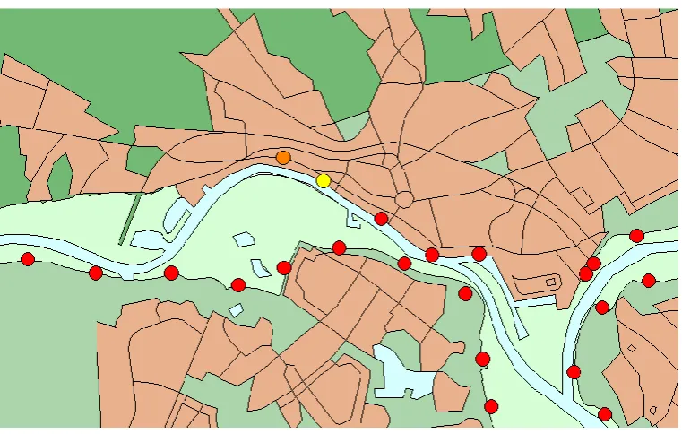
The hydraulic boundary conditions are determined with the “Werkwijze bepaling hydraulische ontwerprandvoorwaarden” of Deltares (Deltares, 2015). In order to determine the hydraulic boundary conditions first the water levels are determined. After that, the crest height is determined. First the hydraulic load on the dike is simulated with “Hydra Zoet”. “Hydra Zoet” is a probabilistic model that combines wind and discharge scenario’ of ‘Rijkswaterstaat’ and is developed for the testing and determination of the hydraulic boundary conditions of water-retaining structures near fresh water with a semi-probabilistic method. With the water levels that are simulated in “Hydra Zoet” and the simulated hydraulic load on the dike, the required crest height of the dike can be determined with the program “PC Overslag” of “Rijkswaterstaat”. For the area around KEMA Laboratories overtopping is not allowed so the maximum overtopping discharge of the dike is set on 0.1 L/s/m.
1.
Location
[image:36.595.91.472.419.661.2]Various locations of the Lower-Rhine are available in ‘Hydra-Zoet’. There is no data available on the exact location of KEMA Laboratories, so the data of a location upstream of the KEMA is used. The data of location 10 on dike ring 47 at kilometer marker 883-884 is used (shown in Figure 26 in yellow). This location is 1.8 kilometers upstream of KEMA Laboratories. The fetch lengths of the area of the KEMA are used as an input for location 10.