NONRESIDENT
TRAINING
COURSE
SEPTEMBER 1998
Navy Electricity and
Electronics Training Series
Module 18—Radar Principles
Although the words “he,” “him,” and “his” are used sparingly in this course to
enhance communication, they are not
PREFACE
By enrolling in this self-study course, you have demonstrated a desire to improve yourself and the Navy. Remember, however, this self-study course is only one part of the total Navy training program. Practical experience, schools, selected reading, and your desire to succeed are also necessary to successfully round out a fully meaningful training program.
COURSE OVERVIEW: To introduce the student to the subject of Radar Principles who needs such a background in accomplishing daily work and/or in preparing for further study.
THE COURSE: This self-study course is organized into subject matter areas, each containing learning objectives to help you determine what you should learn along with text and illustrations to help you understand the information. The subject matter reflects day-to-day requirements and experiences of personnel in the rating or skill area. It also reflects guidance provided by Enlisted Community Managers (ECMs) and other senior personnel, technical references, instructions, etc., and either the occupational or naval standards, which are listed in the Manual of Navy Enlisted Manpower Personnel Classifications and Occupational Standards, NAVPERS 18068.
THE QUESTIONS: The questions that appear in this course are designed to help you understand the material in the text.
VALUE: In completing this course, you will improve your military and professional knowledge. Importantly, it can also help you study for the Navy-wide advancement in rate examination. If you are studying and discover a reference in the text to another publication for further information, look it up.
1998 Edition Prepared by
FTMC Frank E. Sloan and FTCM Gilbert J. Cote'
Published by
NAVAL EDUCATION AND TRAINING PROFESSIONAL DEVELOPMENT
AND TECHNOLOGY CENTER
Sailor’s Creed
“I am a United States Sailor.
I will support and defend the
Constitution of the United States of
America and I will obey the orders
of those appointed over me.
I represent the fighting spirit of the
Navy and those who have gone
before me to defend freedom and
democracy around the world.
I proudly serve my country’s Navy
combat team with honor, courage
and commitment.
TABLE OF CONTENTS
CHAPTER PAGE
1. Radar Fundamentals ... 1-1 2. Radar Subsystems... 2-1 3. Radar Indicators and Antennas... 3-1 4. Radar System Maintenance ... 4-1
APPENDIX
NAVY ELECTRICITY AND ELECTRONICS TRAINING
SERIES
The Navy Electricity and Electronics Training Series (NEETS) was developed for use by personnel in many electrical- and electronic-related Navy ratings. Written by, and with the advice of, senior technicians in these ratings, this series provides beginners with fundamental electrical and electronic concepts through self-study. The presentation of this series is not oriented to any specific rating structure, but is divided into modules containing related information organized into traditional paths of instruction. The series is designed to give small amounts of information that can be easily digested before advancing further into the more complex material. For a student just becoming acquainted with electricity or electronics, it is highly recommended that the modules be studied in their suggested sequence. While there is a listing of NEETS by module title, the following brief descriptions give a quick overview of how the individual modules flow together.
Module 1, Introduction to Matter, Energy, and Direct Current, introduces the course with a short history of electricity and electronics and proceeds into the characteristics of matter, energy, and direct current (dc). It also describes some of the general safety precautions and first-aid procedures that should be common knowledge for a person working in the field of electricity. Related safety hints are located throughout the rest of the series, as well.
Module 2, Introduction to Alternating Current and Transformers, is an introduction to alternating current (ac) and transformers, including basic ac theory and fundamentals of electromagnetism, inductance, capacitance, impedance, and transformers.
Module 3, Introduction to Circuit Protection, Control, and Measurement, encompasses circuit breakers, fuses, and current limiters used in circuit protection, as well as the theory and use of meters as electrical measuring devices.
Module 4, Introduction to Electrical Conductors, Wiring Techniques, and Schematic Reading, presents conductor usage, insulation used as wire covering, splicing, termination of wiring, soldering, and reading electrical wiring diagrams.
Module 5, Introduction to Generators and Motors, is an introduction to generators and motors, and covers the uses of ac and dc generators and motors in the conversion of electrical and mechanical energies.
Module 6, Introduction to Electronic Emission, Tubes, and Power Supplies, ties the first five modules together in an introduction to vacuum tubes and vacuum-tube power supplies.
Module 7, Introduction to Solid-State Devices and Power Supplies, is similar to module 6, but it is in reference to solid-state devices.
Module 8, Introduction to Amplifiers, covers amplifiers.
Module 9, Introduction to Wave-Generation and Wave-Shaping Circuits, discusses wave generation and wave-shaping circuits.
Module 11, Microwave Principles, explains microwave oscillators, amplifiers, and waveguides.
Module 12, Modulation Principles, discusses the principles of modulation.
Module 13, Introduction to Number Systems and Logic Circuits, presents the fundamental concepts of number systems, Boolean algebra, and logic circuits, all of which pertain to digital computers.
Module 14, Introduction to Microelectronics, covers microelectronics technology and miniature and microminiature circuit repair.
Module 15, Principles of Synchros, Servos, and Gyros, provides the basic principles, operations, functions, and applications of synchro, servo, and gyro mechanisms.
Module 16, Introduction to Test Equipment, is an introduction to some of the more commonly used test equipments and their applications.
Module 17, Radio-Frequency Communications Principles, presents the fundamentals of a radio-frequency communications system.
Module 18, Radar Principles, covers the fundamentals of a radar system.
Module 19, The Technician's Handbook, is a handy reference of commonly used general information, such as electrical and electronic formulas, color coding, and naval supply system data.
Module 20, Master Glossary, is the glossary of terms for the series.
Module 21, Test Methods and Practices, describes basic test methods and practices.
Module 22, Introduction to Digital Computers, is an introduction to digital computers.
Module 23, Magnetic Recording, is an introduction to the use and maintenance of magnetic recorders and the concepts of recording on magnetic tape and disks.
Module 24, Introduction to Fiber Optics, is an introduction to fiber optics.
Embedded questions are inserted throughout each module, except for modules 19 and 20, which are reference books. If you have any difficulty in answering any of the questions, restudy the applicable section.
Although an attempt has been made to use simple language, various technical words and phrases have necessarily been included. Specific terms are defined in Module 20, Master Glossary.
Considerable emphasis has been placed on illustrations to provide a maximum amount of information. In some instances, a knowledge of basic algebra may be required.
Throughout the text of this course and while using technical manuals associated with the equipment you will be working on, you will find the below notations at the end of some paragraphs. The notations are used to emphasize that safety hazards exist and care must be taken or observed.
WARNING
AN OPERATING PROCEDURE, PRACTICE, OR CONDITION, ETC., WHICH MAY RESULT IN INJURY OR DEATH IF NOT CAREFULLY OBSERVED OR FOLLOWED.
CAUTION
AN OPERATING PROCEDURE, PRACTICE, OR CONDITION, ETC., WHICH MAY RESULT IN DAMAGE TO EQUIPMENT IF NOT CAREFULLY OBSERVED OR FOLLOWED.
NOTE
INSTRUCTIONS FOR TAKING THE COURSE
ASSIGNMENTS
The text pages that you are to study are listed at the beginning of each assignment. Study these pages carefully before attempting to answer the questions. Pay close attention to tables and illustrations and read the learning objectives. The learning objectives state what you should be able to do after studying the material. Answering the questions correctly helps you accomplish the objectives.
SELECTING YOUR ANSWERS
Read each question carefully, then select the BEST answer. You may refer freely to the text. The answers must be the result of your own work and decisions. You are prohibited from referring to or copying the answers of others and from giving answers to anyone else taking the course.
SUBMITTING YOUR ASSIGNMENTS
To have your assignments graded, you must be enrolled in the course with the Nonresident Training Course Administration Branch at the Naval Education and Training Professional Development and Technology Center (NETPDTC). Following enrollment, there are two ways of having your assignments graded: (1) use the Internet to submit your assignments as you complete them, or (2) send all the assignments at one time by mail to NETPDTC. Grading on the Internet: Advantages to Internet grading are:
• you may submit your answers as soon as you complete an assignment, and
• you get your results faster; usually by the next working day (approximately 24 hours). In addition to receiving grade results for each assignment, you will receive course completion confirmation once you have completed all the
assignments. To submit your assignment answers via the Internet, go to:
http://courses.cnet.navy.mil
Grading by Mail: When you submit answer sheets by mail, send all of your assignments at one time. Do NOT submit individual answer sheets for grading. Mail all of your assignments in an envelope, which you either provide yourself or obtain from your nearest Educational Services Officer (ESO). Submit answer sheets to:
COMMANDING OFFICER NETPDTC N331
6490 SAUFLEY FIELD ROAD PENSACOLA FL 32559-5000
Answer Sheets: All courses include one “scannable” answer sheet for each assignment. These answer sheets are preprinted with your SSN, name, assignment number, and course number. Explanations for completing the answer sheets are on the answer sheet.
Do not use answer sheet reproductions: Use only the original answer sheets that we provide—reproductions will not work with our scanning equipment and cannot be processed. Follow the instructions for marking your answers on the answer sheet. Be sure that blocks 1, 2, and 3 are filled in correctly. This information is necessary for your course to be properly processed and for you to receive credit for your work.
COMPLETION TIME
PASS/FAIL ASSIGNMENT PROCEDURES
If your overall course score is 3.2 or higher, you will pass the course and will not be required to resubmit assignments. Once your assignments have been graded you will receive course completion confirmation.
If you receive less than a 3.2 on any assignment and your overall course score is below 3.2, you will be given the opportunity to resubmit failed assignments. You may resubmit failed assignments only once. Internet students will receive notification when they have failed an assignment--they may then resubmit failed assignments on the web site. Internet students may view and print results for failed assignments from the web site. Students who submit by mail will receive a failing result letter and a new answer sheet for resubmission of each failed assignment.
COMPLETION CONFIRMATION
After successfully completing this course, you will receive a letter of completion.
ERRATA
Errata are used to correct minor errors or delete obsolete information in a course. Errata may also be used to provide instructions to the student. If a course has an errata, it will be included as the first page(s) after the front cover. Errata for all courses can be accessed and viewed/downloaded at:
http://www.advancement.cnet.navy.mil
STUDENT FEEDBACK QUESTIONS
We value your suggestions, questions, and criticisms on our courses. If you would like to communicate with us regarding this course, we encourage you, if possible, to use e-mail. If you write or fax, please use a copy of the Student Comment form that follows this page.
For subject matter questions:
E-mail: [email protected] Phone: Comm: (850) 452-1001, ext. 1728
DSN: 922-1001, ext. 1728 FAX: (850) 452-1370 (Do not fax answer sheets.) Address: COMMANDING OFFICER
NETPDTC N315
6490 SAUFLEY FIELD ROAD PENSACOLA FL 32509-5237 For enrollment, shipping, grading, or completion letter questions
E-mail: [email protected] Phone: Toll Free: 877-264-8583
Comm: (850) 452-1511/1181/1859 DSN: 922-1511/1181/1859
FAX: (850) 452-1370 (Do not fax answer sheets.) Address: COMMANDING OFFICER
NETPDTC N331
6490 SAUFLEY FIELD ROAD PENSACOLA FL 32559-5000
NAVAL RESERVE RETIREMENT CREDIT
Student Comments
Course Title:
NEETS Module 18
Radar Principles
NAVEDTRA:
14190
Date:
We need some information about you:
Rate/Rank and Name: SSN: Command/Unit
Street Address: City: State/FPO: Zip
Your comments, suggestions, etc.:
Privacy Act Statement: Under authority of Title 5, USC 301, information regarding your military status is requested in processing your comments and in preparing a reply. This information will not be divulged without written authorization to anyone other than those within DOD for official use in determining performance.
CHAPTER 1
RADAR FUNDAMENTALS
LEARNING OBJECTIVES
Learning objectives are stated at the beginning of each chapter. These learning objectives serve as a preview of the information you are expected to learn in the chapter. The comprehensive check questions are based on the objectives. By successfully completing the OCC/ECC, you indicate that you have met the objectives and have learned the information. The learning objectives are listed below.
1. Define range, bearing, and altitude as they relate to a radar system.
2. Discuss how pulse width, peak power, and beam width affect radar performance. 3. Describe the factors that contribute to or detract from radar accuracy.
4. Using a block diagram, describe the basic function, principles of operation, and interrelationships of the basic units of a radar system.
5. Explain the various ways in which radar systems are classified, including the standard Army/Navy classification system.
6. Explain the basic operation of cw, pulse, and Doppler radar systems.
INTRODUCTION TO RADAR FUNDAMENTALS
The term RADAR is common in today’s everyday language. You probably use it yourself when referring to a method of recording the speed of a moving object. The term Radar is an acronym made up of the words radio detection and ranging. The term is used to refer to electronic equipment that detect the presence, direction, height, and distance of objects by using reflected electromagnetic energy.
Electromagnetic energy of the frequency used for radar is unaffected by darkness and also penetrates weather to some degree, depending on frequency. It permits radar systems to determine the positions of ships, planes, and land masses that are invisible to the naked eye because of distance, darkness, or weather.
The development of radar into the highly complex systems in use today represents the accumulated developments of many people and nations. The general principles of radar have been known for a long time, but many electronics discoveries were necessary before a useful radar system could be developed. World War II provided a strong incentive to develop practical radar, and early versions were in use soon after the war began. Radar technology has improved in the years since the war. We now have radar systems that are smaller, more efficient, and better than those early versions.
BASIC RADAR CONCEPTS
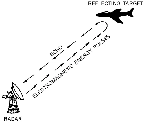
[image:14.612.181.430.248.470.2]The electronics principle on which radar operates is very similar to the principle of sound-wave reflection. If you shout in the direction of a sound-reflecting object (like a rocky canyon or cave), you will hear an echo. If you know the speed of sound in air, you can then estimate the distance and general direction of the object. The time required for a return echo can be roughly converted to distance if the speed of sound is known. Radar uses electromagnetic energy pulses in much the same way, as shown in figure 1-1. The radio-frequency (rf) energy is transmitted to and reflects from the reflecting object. A small portion of the energy is reflected and returns to the radar set. This returned energy is called an ECHO, just as it is in sound terminology. Radar sets use the echo to determine the direction and distance of the reflecting object.
Figure 1-1.—Radar echo.
NOTE: The terms TARGET, RETURN, ECHO, CONTACT, OBJECT, and REFLECTING
OBJECT are used interchangeably throughout this module to indicate a surface or airborne object that has been detected by a radar system.
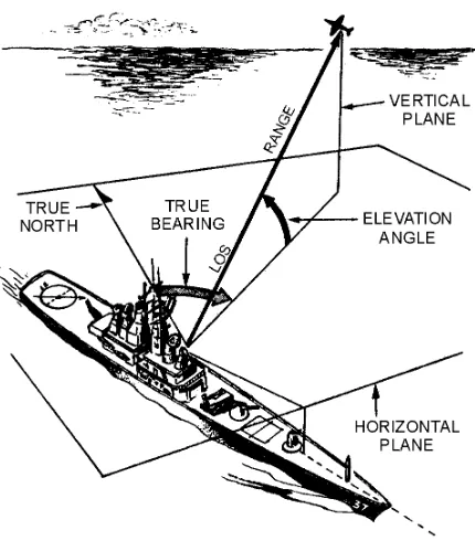
Figure 1-2.—Radar reference coordinates.
This second plane is called the VERTICAL PLANE. The radar location is the center of this
coordinate system. The line from the radar set directly to the object is referred to as the LINE OF SIGHT (los). The length of this line is called RANGE. The angle between the horizontal plane and the los is the ELEVATION ANGLE. The angle measured clockwise from true north in the horizontal plane is called the TRUE BEARING or AZIMUTH angle. These three coordinates of range, bearing, and elevation describe the location of an object with respect to the antenna.
Q1. Radar surface-angular measurements are referenced to true north and measured in what plane? Q2. The distance from a radar set to a target measured along the line of sight is identified by what
term?
RANGE
Radar measurement of range, or distance, is made possible because of the properties of radiated electromagnetic energy. This energy normally travels through space in a straight line, at a constant speed, and will vary only slightly because of atmospheric and weather conditions. The effects atmosphere and weather have on this energy will be discussed later in this chapter; however, for this discussion on determining range, these effects will be temporarily ignored.
Electromagnetic energy travels through air at approximately the speed of light, which is 186,000 STATUTE MILES per second. The Navy uses NAUTICAL MILES to calculate distances; 186,000 statute miles is approximately 162,000 nautical miles. While the distance of the statute mile is approximately 5,280 feet, the distance for a nautical mile is approximately 6,080 feet.
The same answer can be obtained using yards instead of feet. In the following calculation, the 6,080 foot approximation of a nautical mile is converted to 2,027 yards and energy speed is changed from 984 feet to 328 yards per microsecond:
A pulse-type radar set transmits a short burst of electromagnetic energy. Target range is determined by measuring elapsed time while the pulse travels to and returns from the target. Because two-way travel is involved, a total time of 12.36 (6.18 x 2) microseconds per nautical mile will elapse between the start of the pulse from the antenna and its return to the antenna from a target. This 12.36 microsecond time interval is sometimes referred to as a RADAR MILE, RADAR NAUTICAL MILE, or NAUTICAL RADAR MILE. The range in nautical miles to an object can be found by measuring the elapsed time during a round trip of a radar pulse and dividing this quantity by 12.36. In equation form, this is:
For example, if the elapsed time for an echo is 62 microseconds, then the distance is 5 miles, as shown in the following calculation:
Minimum Range
Recall from NEETS, Module 11, Microwave Principles, that the DUPLEXER alternately switches the antenna between the transmitter and receiver so that only one antenna need be used. This switching is necessary because the high-power pulses of the transmitter would destroy the receiver if energy were allowed to enter the receiver. As you probably already realize, timing of this switching action is critical to the operation of the radar system. What you may not realize is that the minimum range ability of the radar system is also affected by this timing. The two most important times in this action are PULSE WIDTH and RECOVERY TIME.
This timing action must be such that during the transmitted pulse (pulse width), only the transmitter can be connected to the antenna. Immediately after the pulse is transmitted, the antenna must be
reconnected to the receiver.
The leading edge of the transmitted pulse causes the duplexer to align the antenna to the transmitter. This action is essentially instantaneous. At the end of the transmitted pulse, the trailing edge of the pulse causes the duplexer to line up the antenna with the receiver; however, this action is not instantaneous. A small amount of time elapses at this point that is referred to as recovery time. Therefore, the total time in which the receiver is unable to receive the reflected pulse is equal to the pulse width plus the recovery time. Note that any reflected pulses from close targets returning before the receiver is connected to the antenna will be undetected. The minimum range, in yards, at which a target can be detected is determined using the following formula (pulse width and recovery time are expressed in microseconds or fractions of microseconds):
For example, minimum range for a radar system with a pulse width of 25 microseconds and a recovery time of 0.1 microseconds is figured as follows:
Most modern radar systems are designed with such small recovery times that this figure can often be ignored when figuring minimum range.
Maximum Range
The frequency of the rf energy in the pulse radiated by a radar is referred to as the CARRIER FREQUENCY of the radar system. The carrier frequency is often a limiting factor in the maximum range capability of a radar system because radio frequency energy above 3,000 megahertz is rapidly attenuated by the atmosphere. This decreases the usable range of radio-frequency energy. Therefore, as the carrier frequency is increased, the transmitted power must also be increased to cover the same range. Long-range coverage is more easily achieved at lower frequencies because atmospheric conditions have less effect on low-frequency energy.
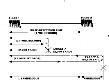
Radar systems radiate each pulse at the carrier frequency during transmit time, wait for returning echoes during listening or rest time, and then radiate a second pulse, as shown in figure 1-3. The number of pulses radiated in one second is called the pulse-repetition frequency (prf), or the pulse-repetition rate (prr). The time between the beginning of one pulse and the start of the next pulse is called PULSE-REPETITION TIME (prt) and is equal to the reciprocal of prf as follows:
Figure 1-3.—Radar pulse relationships.
AMBIGUOUS RETURNS.—The radar timing system must be reset to zero each time a pulse is radiated. This is to ensure that the range detected is measured from time zero each time. The prt of the radar becomes important in maximum range determination because target return times that exceed the prt of the radar system appear at incorrect locations (ranges) on the radar screen. Returns that appear at these incorrect ranges are referred to as AMBIGUOUS RETURNS or SECOND-SWEEP ECHOES.
normal (unambiguous) ranges. The maximum unambiguous range for a given radar system can be determined by the following formula:
Figure 1-4.—Maximum unambiguous range.
Q3. What is the speed of electromagnetic energy traveling through air?
Q4. How much time is required for electromagnetic energy to travel 1 nautical mile and return to the source?
Q5. In addition to recovery time, what determines the minimum range of a radar set?
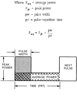
PULSE-REPETITION FREQUENCY AND POWER CALCULATIONS.—The energy content of a continuous-wave radar transmission may be easily figured because the transmitter operates
continuously. However, pulsed radar transmitters are switched on and off to provide range timing information with each pulse. The resulting waveform for a transmitter was shown in figure 1-3. The amount of energy in this waveform is important because maximum range is directly related to transmitter output power. The more energy the radar system transmits, the greater the target detection range will be. The energy content of the pulse is equal to the PEAK (maximum) POWER LEVEL of the pulse
multiplied by the pulse width. However, meters used to measure power in a radar system do so over a period of time that is longer than the pulse width. For this reason, pulse-repetition time is included in the power calculations for transmitters. Power measured over such a period of time is referred to as
AVERAGE POWER. Figure 1-5 illustrates the way this average power would be shown as the total energy content of the pulse. The shaded area represents the total energy content of the pulse; the
system. The figure is drawn just to show you how average power is calculated.) Pulse-repetition time is used to help figure average power because it defines the total time from the beginning of one pulse to the beginning of the next pulse. Average power is figured as follows:
Figure 1-5.—Pulse energy content.
Because 1/prt is equal to prf, the formula may be written as follows:
The product of pulse width (pw) and pulse-repetition frequency (prf) in the above formula is called the DUTY CYCLE of a radar system. The duty cycle is a ratio of the time on to the time off of the transmitter, as shown in figure 1-6. The duty cycle is used to calculate both the peak power and average power of a radar system. The formula for duty cycle is shown below:
Figure 1-6.—Duty cycle.
Since the duty cycle of a radar is usually known, the most common formula for average power is expressed as:
Transposing the above formula gives us a common formula for peak power:
Peak power must be calculated more often than average power. This is because, as previously mentioned, most measurement instruments measure average power directly. An example is shown below:
Where:
Before figuring Pp, you must figure duty cycle as follows:
ANTENNA HEIGHT AND SPEED.—Another factor affecting radar range is antenna height. The high-frequency energy transmitted by a radar system travels in a straight line and does not normally bend to conform to the curvature of the earth. Because of this, the height of both the antenna and the target are factors in detection range. The distance to the horizon (in nautical miles) for a radar system varies with the height of the antenna according to the following formula:
For example, assume antenna height to be 64 feet in the following calculations:
A target at a range greater than the radar horizon will not be detected unless it is high enough to be above the horizon. An example of the antenna- and target-height relationship is shown in figure 1-7.
Figure 1-7.—Radar horizon.
The number of strikes per antenna revolution is referred to as HITS PER SCAN. During each revolution enough pulses must be transmitted to return a usable echo.
NOTE: The more pulses transmitted to a given area (at slower antenna speeds), the greater the number of hits per scan.
As an example, if the antenna rotates at 20 rpm, it completes a revolution in 3 seconds. During this time, a transmitter with a prf of 200 pulses per second (pps) transmits 600 pulses. Since 360 degrees of azimuth must be covered, the following formula shows the number of pulses for each degree of azimuth:
Such a low number of pulses for any given target area greatly increases the likelihood that some targets will be missed entirely; therefore, prf and antenna speed must be matched for maximum efficiency.
Q6. Atmospheric interference with the travel of electromagnetic energy increases with what rf energy characteristic?
Q7. How is prt related to prf?
Q8. What type of radar transmitter power is measured over a period of time?
Q9. What term is used to describe the product of pulse width and pulse-repetition frequency?
BEARING
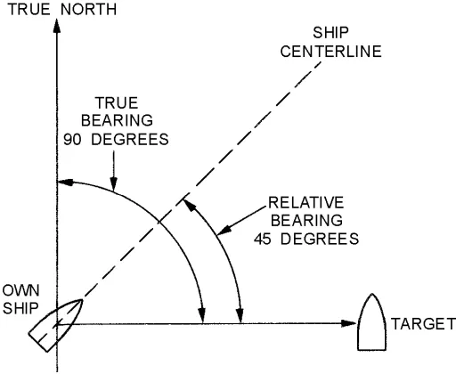
[image:23.612.178.434.484.694.2]The TRUE BEARING (referenced to true north) of a radar target is the angle between true north and a line pointed directly at the target. This angle is measured in the horizontal plane and in a clockwise direction from true north. The bearing angle to the radar target may also be measured in a clockwise direction from the centerline of your own ship or aircraft and is referred to as the RELATIVE BEARING. Both true and relative bearing angles are illustrated in figure 1-8.
The antennas of most radar systems are designed to radiate energy in a one-directional lobe or beam that can be moved in bearing simply by moving the antenna. As you can see in figure 1-9, the shape of the beam is such that the echo signal strength varies in amplitude as the antenna beam moves across the target. At antenna position A, the echo is minimal; at position B, where the beam axis is pointing directly at the target, the echo strength is maximum. Thus, the bearing angle of the target can be obtained by moving the antenna to the position at which the echo is strongest. In actual practice, search radar antennas move continuously; the point of maximum echo return is determined by the detection circuitry as the beam passes the target or visually by the operator. Weapons-control and guidance radar systems are positioned to the point of maximum signal return and maintained at that position either manually or by automatic tracking circuits.
Figure 1-9.—Determination of bearing.
ALTITUDE
Many radar systems are designed to determine only the range and bearing of an object. Such radar systems are called TWO-DIMENSIONAL (2D) radars. In most cases these systems are further described as SEARCH RADAR SYSTEMS and function as early-warning devices that search a fixed volume of space. The range and bearing coordinates provide enough information to place the target in a general area with respect to the radar site and to determine distance, direction of travel, and relative speed. However, when action must be taken against an airborne target, altitude must be known as well. A search radar system that detects altitude as well as range and bearing is called a THREE-DIMENSIONAL (3D) radar.
phase can be predetermined to create an orderly scanning pattern that covers the entire vertical plane. Electronic scanning permits automatic compensation for an unstable radar platform (site), such as a ship at sea. Error signals are produced by the roll and pitch of the ship and are used to correct the radar beam to ensure complete elevation coverage.
Figure 1-10.—Electronic elevation scan.
Mechanical elevation scanning is achieved by mechanically moving the antenna or radiation source. Weapons-control and tracking radar systems commonly use mechanical elevation scanning techniques. Most electronically scanned radar systems are used as air search radars. Some older air-search radar systems use a mechanical elevation scanning device; however, these are being replaced by electronically scanned radar systems.
Q10. What type of target bearing is referenced to your ship? Q11. What type of radar detects range, bearing, and height?
Q12. What characteristic(s) of radiated energy is (are) altered to achieve electronic scanning?
TARGET RESOLUTION
The TARGET RESOLUTION of a radar is its ability to distinguish between targets that are very close together in either range or bearing. Weapons-control radar, which requires great precision, should be able to distinguish between targets that are only yards apart. Search radar is usually less precise and only distinguishes between targets that are hundreds of yards or even miles apart. Resolution is usually divided into two categories; RANGE RESOLUTION and BEARING RESOLUTION.
Range Resolution
The above formula is often written as:
For example, if a radar system has a pulse width of 5 microseconds, the range resolution is calculated as follows:
In the above example, targets on the same bearing would have to be separated by more than 820 yards to show up as two targets on your indicator.
Bearing Resolution
RADAR ACCURACY
Radar accuracy is a measure of the ability of a radar system to determine the correct range, bearing, and, in some cases, height of an object. The degree of accuracy is primarily determined by the resolution of the radar system. Some additional factors affecting accuracy are pulse shape and atmospheric
conditions. Pulse Shape
In the case of a pulse radar, the shape and width of the rf pulse influences minimum range, range accuracy, and maximum range. The ideal pulse shape is a square wave having vertical leading and trailing edges. However, equipments do not usually produce the ideal waveforms.
The factors influencing minimum range are discussed first. Since the receiver cannot receive target reflections while the transmitter is operating, you should be able to see that a narrow pulse is necessary for short ranges. A sloping trailing edge extends the width of the transmitter pulse, although it may add very little to the total power generated. Therefore, along with a narrow pulse, the trailing edge should be as near vertical as possible.
A sloping leading edge also affects minimum range as well as range accuracy since it provides no definite point from which to measure elapsed time on the indicator time base. Using a starting point at the lower edge of the pulse’s leading edge would increase minimum range. Using a starting point high up on the slope would reduce the accuracy of range measurements at short ranges which are so vital for accurate solution of the fire-control problem.
Maximum range is influenced by pulse width and pulse repetition frequency (prf). Since a target can reflect only a very small part of the transmitted power, the greater the transmitted power, the greater the strength of the echo that could be received. Thus, a transmitted pulse should quickly rise to its maximum amplitude, remain at this amplitude for the duration of the desired pulse width, and decay instantaneously to zero. Figure 1-12 illustrates the effects of pulse shapes.
Figure 1-12.—Pulse shapes and effects.
Atmospheric Conditions
electromagnetic wavefront. The path followed by electromagnetic energy in the atmosphere, whether direct or reflected, usually is slightly curved; and the speed is affected by temperature, atmospheric pressure, and the amount of water vapor present in the atmosphere, which all affect the refractive index. As altitude increases, the combined effects of these influences, under normal atmospheric conditions, cause a small, uniform increase in signal speed. This increase in speed causes the travel path to curve slightly downward, as shown in figure 1-13. The downward curve extends the radar horizon beyond a line tangent to the earth, as illustrated in figure 1-14.
Figure 1-13.—Wavefront path.
Figure 1-14.—Extension of the radar horizon.
REFRACTION is the bending of electromagnetic waves caused by a change in the density of the medium through which the waves are passing. A visible example of electromagnetic refraction is the apparent displacement of underwater objects caused by the bending of light as it passes from the atmosphere into the water. An INDEX OF REFRACTION has been established which indicates the degree of refraction, or bending, caused by different substances. Because the density of the atmosphere changes with altitude, the index of refraction changes gradually with height.
The temperature and moisture content of the atmosphere normally decrease uniformly with an increase in altitude. However, under certain conditions the temperature may first increase with height and then begin to decrease. Such a situation is called a temperature inversion. An even more important deviation from normal may exist over the ocean. Since the atmosphere close to the surface over large bodies of water may contain more than a normal amount of moisture, the moisture content may decrease more rapidly at heights just above the sea. This effect is referred to as MOISTURE LAPSE.
Either temperature inversion or moisture lapse, alone or in combination, can cause a large change in the refraction index of the lowest few-hundred feet of the atmosphere. The result is a greater bending of the radar waves passing through the abnormal condition. The increased bending in such a situation is referred to as DUCTING and may greatly affect radar performance. The radar horizon may be extended or reduced, depending on the direction the radar waves are bent. The effect of ducting on radar waves is illustrated in figure 1-15.
Figure 1-15.—Ducting effect on the radar wave.
Another effect of the atmosphere on radar performance is caused by particles suspended in the air. Water droplets and dust particles diffuse radar energy through absorption, reflection, and scattering so less energy strikes the target. Consequently, the return echo is smaller. The overall effect is a reduction in usable range that varies widely with weather conditions. The higher the frequency of a radar system, the more it is affected by weather conditions such as rain or clouds. In some parts of the world, dust
suspended in the air can greatly decrease the normal range of high-frequency radar.
Q13. What term is used to describe the ability of a radar system to distinguish between targets that are close together?
Q14. The degree of bearing resolution for a given radar system depends on what two factors? Q15. What happens to the speed of electromagnetic energy traveling through air as the altitude
Q16. What term is used to describe a situation in which atmospheric temperature first increases with altitude and then begins to decrease?
RADAR PRINCIPLES OF OPERATION
Radar systems, like other complex electronics systems, are composed of several major subsystems and many individual circuits. This section will introduce you to the major subsystems common to most radar sets. A brief functional description of subsystem principles of operation will be provided. A much more detailed explanation of radar subsystems will be given in chapters 2 and 3. Since most radar systems in use today are some variation of the pulse radar system, the units discussed in this section will be those used in pulse radar. All other types of radar use some variation of these units, and these variations will be explained as necessary.
RADAR COMPONENTS
Pulse radar systems can be functionally divided into the six essential components shown in
figure 1-16. These components are briefly described in the following paragraphs and will be explained in detail after that:
Figure 1-16.—Functional block diagram of a basic radar system.
• The SYNCHRONIZER (also referred to as the TIMER or KEYER) supplies the synchronizing signals that time the transmitted pulses, the indicator, and other associated circuits.
• The TRANSMITTER generates electromagnetic energy in the form of short, powerful pulses. • The DUPLEXER allows the same antenna to be used for transmitting and receiving.
• The INDICATOR produces a visual indication of the echo pulses in a manner that, at a minimum, furnishes range and bearing information.
While the physical configurations of radar systems differ, any radar system can be represented by the functional block diagram in figure 1-16. An actual radar set may have several of these functional
components within one physical unit, or a single one of these functions may require several physical units. However, the functional block diagram of a basic radar set may be used to analyze the operation of almost any radar set.
In the following paragraphs, a brief description of the operation of each of the major components is given.
Synchronizer (Timer)
The synchronizer ensures that all circuits connected with the radar system operate in a definite timed relationship. It also times the interval between transmitted pulses to ensure that the interval is of the proper length. Timing pulses are used to ensure synchronous circuit operation and are related to the prf. The prf can be set by any stable oscillator, such as a sine-wave oscillator, multivibrator, or a blocking oscillator. That output is then applied to pulse-shaping circuits to produce timing pulses. Associated components can be timed by the output of the synchronizer or by a timing signal from the transmitter as it is turned on.
Transmitter
The transmitter generates powerful pulses of electromagnetic energy at precise intervals. The required power is obtained by using a high-power microwave oscillator, such as a magnetron, or a microwave amplifier, such as a klystron, that is supplied by a low-power rf source. (The construction and operation of microwave components can be reviewed in NEETS, Module 11, Microwave Principles.) The high-power generator, whether an oscillator or amplifier, requires operating power in the form of a properly-timed, high-amplitude, rectangular pulse. This pulse is supplied by a transmitter unit called the MODULATOR. When a high-power oscillator is used, the modulator high-voltage pulse switches the oscillator on and off to supply high-power electromagnetic energy. When a microwave power amplifier is used, the modulator pulse activates the amplifier just before the arrival of an electromagnetic pulse from a preceding stage or a frequency-generation source. Normally, because of the extremely high voltage involved, the modulator pulse is supplied to the cathode of the power tube and the plate is at ground potential to shield personnel from shock hazards. The modulator pulse may be more than 100,000 volts in high-power radar transmitters. In any case, radar transmitters produce voltages, currents, and radiation hazards that are extremely dangerous to personnel. Safety precautions must always be strictly observed when working in or around a radar transmitter.
Duplexer
Antenna System
The antenna system routes the pulse from the transmitter, radiates it in a directional beam, picks up the returning echo, and passes it to the receiver with a minimum of loss. The antenna system includes the antenna, transmission lines and waveguide from the transmitter to the antenna, and the transmission line and waveguide from the antenna to the receiver. In some publications the duplexer is included as a component of the antenna system.
Receiver
The receiver accepts the weak echo signals from the antenna system, amplifies them, detects the pulse envelope, amplifies the pulses, and then routes them to the indicator. One of the primary functions of the radar receiver is to convert the frequency of the received echo signal to a lower frequency that is easier to amplify. This is because radar frequencies are very high and difficult to amplify. This lower frequency is called the INTERMEDIATE FREQUENCY (IF). The type of receiver that uses this frequency conversion technique is the SUPER HETERODYNE RECEIVER. Superheterodyne receivers used in radar systems must have good stability and extreme sensitivity. Stability is ensured by careful design and the overall sensitivity is greatly increased by the use of many IF stages.
Indicator
The indicator uses the received signals routed from the radar receiver to produce a visual indication of target information. The cathode-ray oscilloscope is an ideal instrument for the presentation of radar data. This is because it not only shows a variation of a single quantity, such as voltage, but also gives an indication of the relative values of two or more quantities. The sweep frequency of the radar indicator is determined by the pulse-repetition frequency of the radar system. Sweep duration is determined by the setting of the range-selector switch. Since the indicator is so similar to an oscilloscope, the term RADAR SCOPE is commonly used when referring to radar indicators.
Q17. What radar subsystem supplies timing signals to coordinate the operation of the complete system?
Q18. When a transmitter uses a high-power oscillator to produce the output pulse, what switches the oscillator on and off?
Q19. What radar component permits the use of a single antenna for both transmitting and receiving?
SCANNING
Radar systems are often identified by the type of SCANNING the system uses. Scanning is the systematic movement of a radar beam in a definite pattern while searching for or tracking a target. The type and method of scanning used depends on the purpose and type of radar and on the antenna size and design. In some cases, the type of scan will change with the particular system mode of operation. For example, in a particular radar system, the search mode scan may be quite different from that of the track mode scan.
Stationary-Lobe Scanning
A SINGLE STATIONARY-LOBE SCANNING SYSTEM is the simplest type of scanning. This method produces a single beam that is stationary in relation to the antenna. The antenna is then
radar. A two-dimensional search radar, however, does use a single-lobe that is scanned in a 360-degree pattern because automatic tracking circuits are not normally used in 2D radars.
Single-lobe scanning is unsuitable for use as a tracking radar for several reasons. For example, let’s assume that a target is somewhere on the lobe axis and the receiver is detecting signals reflected from the target. If these reflected signals begin to decrease in strength, the target likely has flown off the lobe axis. In this case, the beam must be moved to continue tracking. The beam might be moved by an operator tracking the target with an optical sight, but such tracking is slow, inaccurate, and limited by conditions of visibility. An automatic tracking system would require that the beam SCAN, or search, the target area in such a case.
Again, assume that a missile is riding (following) the axis of a single beam. The strength of the signals it receives (by means of a radar receiver in the missile) will gradually decrease as its distance from the transmitter increases. If the signal strength decreases suddenly, the missile will know, from built-in detection circuitry, that it is no longer on the axis of the lobe. But it will not know which way to turn to get back on the axis. A simple beam does not contain enough information for missile guidance.
Methods of Beam Scanning
The two basic methods of beam scanning are MECHANICAL and ELECTRONIC. In mechanical scanning, the beam can be moved in various ways: (1) The entire antenna can be moved in the desired pattern; (2) the energy feed source can be moved relative to a fixed reflector; or (3) the reflector can be moved relative to a fixed source. In electronic scanning, the beam is effectively moved by such means as (1) switching between a set of feeder sources, (2) varying the phasing between elements in a multielement array, or (3) comparing the amplitude and phase differences between signals received by a multielement array. A combination of mechanical and electronic scanning is also used in some antenna systems.
MECHANICAL SCANNING.—The most common type of mechanical scanning is the rotation of the antenna through 360 degrees to obtain azimuth coverage. Most search radar sets use this method. A common form of scanning for target tracking or missile beam-rider systems is CONICAL (cone-like) SCANNING. This is generally accomplished mechanically by NUTATING the rf feed point.
Nutation is difficult to describe in words but easy to demonstrate. Hold a pencil in two hands. While holding the eraser end as still as possible, swing the point in a circular motion. This motion of the pencil is referred to as nutation; the pencil point corresponds to the open, or transmitting, end of the waveguide antenna. The important fact to remember is that polarization of the beam is not changed during the
scanning cycle. This means that the axis of the moving feeder does not change either horizontal or vertical orientation while the feeder is moving. You might compare the feeder movement to that of a ferris wheel; that is, the vertical orientation of each seat remains the same regardless of the position of the wheel.
Recall that a waveguide is a metal pipe, usually rectangular in cross section, used to conduct the rf energy from the transmitter to the antenna. The open end of the waveguide faces the concave side of the reflector and the rf energy it emits is bounced from the reflector surface.
A conical scan can be generated by nutation of the waveguide. In this process the axis of the waveguide itself is moved through a small conical pattern. In an actual installation of a nutating waveguide, the three-dimensional movement is fast and of small amplitude. To an observer, the waveguide appears merely to be vibrating slightly.
the path of the lobe axis is a circle. Within the useful range of the beam, the inner edge of the lobe always overlaps the axis of scan.
Figure 1-17.—Conical scanning.
Now assume that we use a conically scanned beam for target tracking. If the target is on the scan axis, the strength of the reflected signals remains constant (or changes gradually as the range changes). But if the target is slightly off the axis, the amplitude of the reflected signals will change at the scan rate. For example, if the target is to the left of the scan axis, as shown in figure 1-18, the reflected signals will be of maximum strength as the lobe sweeps through the left part of its cone; the signals will quickly decrease to a minimum as the lobe sweeps through the right part. Information on the instantaneous position of the beam, relative to the scan axis, and on the strength of the reflected signals is fed to a computer. Such a computer in the radar system is referred to as the angle-tracking or angle-servo circuit (also angle-error detector). If the target moves off the scan axis, the computer instantly determines the direction and amount of antenna movement required to continue tracking. The computer output is used to control servomechanisms that move the antenna. In this way, the target is tracked accurately and
Figure 1-18.—Reflected signal strength.
Q20. What is the simplest type of scanning?
Q21. How does the operator of a single-lobe scanning system determine when the target moves off the lobe axis?
Q22. What are the two basic methods of scanning?
Q23. Rotation of an rf-feed source to produce a conical scan pattern is identified by what term?
ELECTRONIC SCANNING.—Electronic scanning can accomplish lobe motion more rapidly than, and without the inherent maintenance disadvantages of, the mechanical systems. Because electronic scanning cannot generally cover as large an area of space, it is sometimes combined with mechanical scanning in particular applications.
With MONOPULSE (SIMULTANEOUS) LOBING, all range, bearing, and elevation-angle information of a target is obtained from a single pulse. Monopulse scanning is used in fire-control tracking radars.
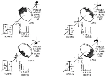
Figure 1-19.—Monopulse scanning.
The amplitude of returned signals received by each horn is continuously compared with those received in the other horns. Error signals are generated which indicate the relative position of the target with respect to the axis of the beam. Angle servo circuits receive these error signals and correct the position of the radar beam to keep the beam axis on target.
The TRAVERSE (BEARING) SIGNAL is made up of signals from horn A added to C and from horn B added to D. By waveguide design, the sum of B and D is made 180 degrees out of phase with the sum of A and C. These two are combined and the traverse signal is the difference of (A + C) − (B + D). Since the horns are positioned as shown in figure 1-19, the relative amplitudes of the horn signals give an indication of the magnitude of the traverse error. The elevation signal consists of the signals from horns C and D added 180 degrees out of phase with horns A and B [(A + B) − (C + D)]. The sum, or range, signal is composed of signals from all four feedhorns added together in phase. It provides a reference from which target direction from the center of the beam axis is measured. The range signal is also used as a phase reference for the traverse and elevation-error signals.
The traverse and elevation error signals are compared in the radar receiver with the range or reference signal. The output of the receiver may be either positive or negative pulses; the amplitudes of the pulses are proportional to the angle between the beam axis and a line drawn to the target. The polarities of the output pulses indicate whether the target is above or below, to the right or to the left of the beam axis. Of course, if the target is directly on the line of sight, the output of the receiver is zero and no angle-tracking error is produced.
An important advantage of a monopulse-tracking radar over radar using conical scan is that the instantaneous angular measurements are not subject to errors caused by target SCINTILLATION.
rest of the pulse train; no such cross-section fluctuations can affect the measurement. An additional advantage of monopulse tracking is that no mechanical action is required.
ELECTRONIC SCANNING used in search radar systems was explained in general terms earlier in this chapter during the discussion of elevation coverage. This type of electronic scanning is often called FREQUENCY SCANNING. An in-depth explanation of frequency scanning theory can be found in the fire control technician rate training manuals.
RADAR TRANSMISSION METHODS
Radar systems are normally divided into operational categories based on energy transmission methods. Up to this point, we have mentioned only the pulse method of transmission to illustrate basic radar concepts. Although the pulse method is the most common method of transmitting radar energy, two other methods are sometimes used in special applications. These are the continuous-wave (cw) method and the frequency modulation (fm) method. All three basic transmission methods are often further subdivided to designate specific variations or combinations.
CONTINUOUS-WAVE METHOD
When radio-frequency energy transmitted from a fixed point continuously strikes an object that is either moving toward or away from the source of the energy, the frequency of the reflected energy is changed. This shift in frequency is known as the DOPPLER EFFECT. The difference in frequency between the transmitted and reflected energy indicates both the presence and the speed of a moving target.
Doppler Effect
A common example of the Doppler effect in action is the changing pitch of the whistle of an approaching train. The whistle appears to change pitch from a high tone, as the train approaches, to a lower tone as it moves away from the observer. As the train approaches, an apparent increase in frequency (an increase in pitch) is heard; as the train moves away, an apparent decrease in frequency (a decrease in pitch) is heard. This pitch variation is known as the Doppler effect.
Figure 1-20.—Transmitter moving relative to an observer.
In 1 second the transmitter moves 360 feet and transmits 60 hertz. At the end of 1 second, the first cycle of the transmitted signal reaches the observer, just as the sixtieth cycle is leaving the transmitter at point P1. Under these conditions the 60 hertz emitted is located between the observer and point P1. Notice that this distance is only 720 feet (1,080 minus 360). The 60 hertz is spread over the distance from point P1 to the observer and has a wavelength of just 12 feet (720 divided by 60). To find the new
frequency, use the following formula:
The original frequency, 60 hertz, has changed to an apparent frequency of 90 hertz. This new frequency only applies to the observer. Notice that the Doppler frequency variation is directly
proportional to the velocity of the approaching transmitter. The faster the transmitter moves toward the observer, the greater the number of waves that will be crowded into the space between the transmitter and the observer.
Suppose the transmitter were stationary and the observer moving. When approaching the transmitter, the observer would encounter waves per unit of time. As a result, the observer would hear a higher pitch than the transmitter would actually emit.
If the transmitter were traveling away from the observer, as shown in view B of figure 1-20, the first cycle would leave the transmitter at point P and the sixtieth at point P2. The first cycle would reach the observer when the transmitter reached P2. You would then have 60 cycles stretched out over 1,080 plus 360 feet, a total of 1,440 feet. The wavelength of these 60 hertz is 1,440/60, or 24 feet. The apparent frequency is 1,080 divided by 24, or 45 hertz.
Uses of CW Doppler System
The Doppler method is the best means of detecting fast-moving objects that do not require range
resolution. As a moving object approaches the transmitter, it encounters and reflects more waves per unit of time. The amount of frequency shift produced is very small in relation to the carrier frequency. This is because the velocity of propagation of the signal is very high compared to the speed of the target. However, because the carrier frequencies used in radar are high, larger frequency shifts (in the audio-frequency range) are produced. The amount of shift is proportional to the speed of the reflecting object. One-quarter cycle shift at 10,000 megahertz will provide speed measurements accurate to a fraction of a percent.
If an object is moving, its velocity, relative to the radar, can be detected by comparing the transmitter frequency with the echo frequency (which differs because of the Doppler shift). The DIFFERENCE or BEAT FREQUENCY, sometimes called the DOPPLER FREQUENCY (fd), is related to object velocity.
The separation of the background and the radar contact is based on the Doppler frequency that is caused by the reflection of the signal from a moving object. Disadvantages of the Doppler system are that it does not determine the range of the object, nor is it able to differentiate between objects when they lie in the same direction and are traveling at the same speed. Moreover, it does not "see" stationary or slow-moving objects, which a pulse radar system can detect.
To track an object with cw Doppler, you must determine the radar range. Since the Doppler frequency is not directly related to range, another method is needed to determine object range. By using two separate transmitters that operate at two different frequencies (f1 and f 2), you can determine range by measuring the relative phase difference between the two Doppler frequencies. In such a system, a mixer is used to combine the two transmitted frequencies and to separate the two received frequencies. This permits the use of one transmitting and receiving antenna.
Instead of using two transmitter frequencies, you can find the range by sweeping the transmitter frequency uniformly in time to cover the frequency range from f1 to f2. The beat, or difference, frequency between the transmitted and received signals is then a function of range. In this type of radar, the velocity as well as range is measured.
Q24. The Doppler effect causes a change in what aspect of rf energy that strikes a moving object? Q25. The Doppler variation is directly proportional to what radar contact characteristic?
Q26. The Doppler method of object detection is best for what type objects?
Q27. The beat frequency in a swept-frequency transmitter provides what contact information?
FREQUENCY-MODULATION METHOD
In the frequency-modulation method, the transmitter radiates radio-frequency waves. The frequency of these rf waves is continually increasing and decreasing from a fixed reference frequency. At any instant, the frequency of the returned signal differs from the frequency of the radiated signal. The amount of the difference frequency is determined by the time it took the signal to travel the distance from the transmitter to the object.
Figure 1-21.—Frequency-modulation chart.
The frequency regularly changes 40 megahertz with respect to time; therefore, its value at any time during its cycle can be used as the basis for computing the time elapsed after the start of the frequency cycle. For example, at T0 the transmitter sends a 420-megahertz signal toward an object. It strikes the object and returns to the receiver at T1, when the transmitter is sending out a new frequency of 440 megahertz. At T1, the 420-megahertz returned signal and the 440-megahertz transmitter signal are fed to the receiver simultaneously. When the two signals are mixed in the receiver, a beat frequency results. The beat frequency varies directly with the distance to the object, increasing as the distance increases. Using this information, you can calibrate a device that measures frequency to indicate range.
This system works well when the detected object is stationary. It is used in aircraft altimeters which give a continuous reading of the height above the earth of the aircraft. The system is not satisfactory for locating moving objects. This is because moving targets produce a frequency shift in the returned signal because of the Doppler effect; this affects the accuracy of the range measurement.
PULSE-MODULATION METHOD
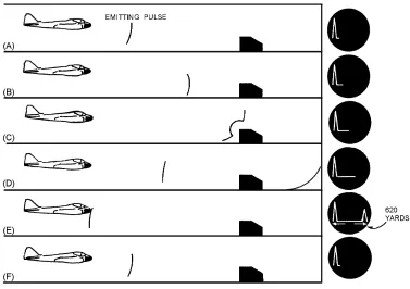
Figure 1-22.—Pulse detection.
PULSE-DOPPLER METHOD
Pulse radar systems may be modified to use the Doppler effect to detect a moving object.
A requirement for any Doppler radar is COHERENCE; that is, some definite phase relationship must exist between the transmitted frequency and the reference frequency, which is used to detect the Doppler shift of the receiver signal. Moving objects are detected by the phase difference between the target signal and background noise components. Phase detection of this type relies on coherence between the
transmitter frequency and the receiver reference frequency.
In coherent detection, a stable cw reference oscillator signal, which is locked in phase with the transmitter during each transmitted pulse, is mixed with the echo signal to produce a beat or difference signal. Since the reference oscillator and the transmitter are locked in phase, the echoes are effectively compared with the transmitter in frequency and phase.
The phase relationships of the echoes from fixed objects to the transmitter is constant and the amplitude of the beat signal remains constant. A beat signal of varying amplitude indicates a moving object. This is because the phase difference between the reference oscillator signal and the echo signal changes as the range to the reflecting object changes. The constant amplitude beat signal is filtered out in the receiver. The beat signal of varying amplitude is sent to the radar indicator scope for display.
Q28. What factor determines the difference between the transmitted frequency and the received frequency in an fm transmitter?
Q29. What type of objects are most easily detected by an fm system?
Q31. What transmission method uses a stable cw reference oscillator, which is locked in phase with the transmitter frequency?
RADAR CLASSIFICATION AND USE
Radar systems, like cars, come in a variety of sizes and have different performance specifications. Some radar systems are used for air-traffic control at airports and others are used for long-range
surveillance and early-warning systems. A radar system is the heart of a missile guidance system. Small portable radar systems that can be maintained and operated by one person are available as well as systems that occupy several large rooms.
MILITARY CLASSIFICATION OF RADAR SYSTEMS
The large number of radar systems used by the military has forced the development of a joint-services classification system for accurate identification. The Federal Aviation Agency (FAA) also makes extensive use of radar systems for commercial aircraft in-flight and landing control, but does not use the military classification system.
Radar systems are usually classified according to specific function and installation vehicle. Some common examples are listed below:
FUNCTION INSTALLATION VEHICLE
Search Ground or land based
Track Airborne
Height-finder Shipboard
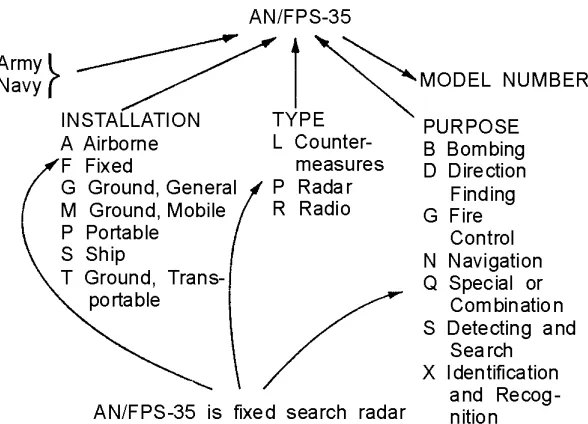
Table 1-1.—Table of Equipment Indicators
TABLE OF EQUIPMENT INDICATORS Installation
(1st letter)
Type of Equipment (2d letter)
Purpose (3rd letter)
Miscellaneous Identification
A—Piloted aircraft A—invisible light, heat radiation
B—Bombing X, Y, Z—Changes in voltage, phase, or frequency B—Underwater mobile,
submarine
C—Carrier C—Communications (receiving and transmitting
T—Training
D—Pilotless carrier D—Radiac D—Direction finder reconnaissance and/or surveillance
(V)—Variable grouping
F—Fixed ground G—Telegraph or Teletype E—Ejection and/or release G—General ground use I—Interphone and public
address
G—Fire control, or search-light directing
K—Amphibious J—Electromechanical or Inertial wire covered
H—Recording and/or reproducing (graphic meteorological and sound) M—Ground, mobile K—Telemetering K—Computing
P—Portable L—Countermeasures M—Maintenance and/or test assemblies (including tools)
S—Water M—Meteorological N—Navigational aids (including altimeters, beacons, compasses, racons, depth sounding, approach and landing) T—Ground, transportable N—Sound in air Q—Special, or
combination of purposes U—General utility P—Radar R—Receiving, passive
detecting V—Ground, vehicular Q—Sonar and underwater
sound
S—Detecting and/or range and bearing, search W—Water surface and
under water combination
R—Radio T—Transmitting
Z—Piloted and pilotless airborne vehicle combination
S—Special types, magnetic, etc., or combinations of types
W—Automatic flight or remote control
T—Telephone (wire) X—Identification and recognition
V—Visual and visible light Y—Surveillance (search detect, and multiple target tracking) and control (both fire control and air control) W—Armament (peculiar to
armament, not otherwise covered)
Figure 1-23.—Joint service classification system.
RADAR FUNCTIONS
No single radar system has yet been designed that can perform all of the many radar functions required by the military. Some of the newer systems combine several functions that formerly required individual radar systems, but no single system can fulfill all the requirements of modern warfare. As a result, modern warships, aircraft, and shore stations usually have several radar systems, each performing a different function.
One radar system, called SEARCH RADAR, is designed to continuously scan a volume of space to provide initial detection of all targets. Search radar is almost always used to detect and determine the position of new targets for later use by TRACK RADAR. Track radar provides continuous range, bearing, and elevation data on one or more targets. Most of the radar systems used by the military are in one of these two categories, though the individual radar systems vary in design and capability.
Some radar systems are designed for specific functions that do not precisely fit into either of the above categories. The radar speed gun is an example of radar designed specifically to measure the speed of a target. The military uses much more complex radar systems that are adapted to detect only fast-moving targets such as aircraft. Since aircraft usually move much faster than weather or surface targets, velocity-sensitive radar can eliminate unwanted clutter from the radar indicator. Radar systems that detect and process only moving targets are called MOVING-TARGET INDICATORS (mti) and are usually combined with conventional search radar.
Another form of radar widely used in military and civilian aircraft is the RADAR ALTIMETER. Just as some surface-based radars can determine the height of a target, airborne radar can determine the