Bubble enhanced heat transfer from a vertical heated surface
Brian Donnellya,*, Darina B. Murraya & Tadhg S. O'Donovanb
aDepartment of Mechanical & Manufacturing Engineering, Trinity College Dublin, Ireland
bSchool of Engineering & Physical Sciences, Heriot-Watt University, Edinburgh, United Kingdom
Abstract
A rising bubble in a liquid can greatly enhance heat transfer from heated surfaces by acting like a bluff body, displacing fluid as it moves and via the wake generated by the bubble, increasing the mixing of the liquid. The current research quantifies the effect a single free rising ellipsoidal air bubble has on heat transfer from a vertical heated block immersed in water. By measuring the time varying heat transfer and tracking the bubble dynamics, further understanding of the heat transfer mechanism is achieved. Both the plane in which the bubble oscillates and the proximity of the bubble path are shown to influence the surface heat transfer.
Keywords: Bubble, Heat Transfer, Buoyancy Driven
___________________________________________________________________________ *Corresponding Author. Tel.: +353-1-896-3920; Fax.: +353-1-679-5554
1. Introduction
Bubbly flows occur in many engineering applications such as steam generation, electronic cooling systems and chemical reactors. These bubbles can be present either due to phase change or by addition of a gas to the flow. An important aspect of bubble dynamics is the interaction between a rising bubble and a vertical heated surface. It is known that this can increase heat transfer from the surface and is an effective and efficient method for doing so. In an earlier study related to the present investigation, Delauré et al. [2003] investigated heat transfer enhancement from a vertical heated block due to a single rising ellipsoidal air bubble in water. Digital Particle Image Velocimetry (DPIV) was performed in order to explore the mechanism of wake generation and interaction with the heated surface. From this, velocity vector plots clearly illustrated the generation of so called “horse shoe” vortices responsible for increased mass flow in the vicinity of the heated surface. Two enhancement mechanisms were identified; first the heat transfer coefficient was found to respond closely to changes in flow velocity, with the shedding of vortices interacting with the thermal boundary layer in a positive or a negative manner. Secondly, the zigzagging motion of the bubble draws cooler water in from the surroundings which impacts on the block surface. It was found that a combination of the two mechanisms results in the largest heat flux enhancement.
reduction in evaporation was compensated by the higher velocity and therefore higher wake turbulence. In a study by Atmane and Murray [2001] on bubble dynamics in nucleate boiling around a cylinder, heat flux enhancement of up to 7 times was recorded using a similar technique to the present study, with the maximum occurring when the bubble was directly above the sensor. It was found that heat transfer was affected by both bubble detachment and by the wake generated by the bubble, evidenced by the long enhancement times. Thorncroft and Klausner [1999] conclude that sliding bubbles can account for as much as 52% of the total energy transfer, outweighing the contribution of bubble nucleation.
In the study of Qiu and Dhir [2002], holographic interferometry is used to visualise both the near and far wake of the bubble for angles of plate inclination of 15º and 75º from the horizontal. At 15º the thermal boundary layer is seen to expand as the liquid tries to flow around the bubble. Vortices were observed to form downstream of the bubble, detach, and move into the bulk fluid where they dissipated. This results in an increase in heat transfer as heated fluid is moved away from the surface and cooler fluid replaces it. For plate angles of 75º the thermal boundary layer was no longer laminar and even without the bubble vortices were observed to roll over the boundary layer. Thus, the scope for heat transfer enhancement by small bubbles at 75º inclination was limited.
performed in a plane perpendicular to the bubble flow direction. This showed the alternate generation of a pair of counter-rotating vortices close to the bubble base.
By using the hydrogen bubble tracer technique, Bhaga and Weber [1981] visualised both a steady wake with a standing eddy and open unsteady wakes behind bubbles rising in liquids of different viscosity. A shape regime map was also provided and shown to depend on the Morton, Weber and Reynolds numbers. This map allows us to predict the expected shape of the bubble i.e. spherical, ellipsoidal, cap etc.
The work of Ellingsen and Risso [2001] confirmed the sinusoidal motion of the bubble and the drift described by Brücker [1999] using smaller bubbles (approximately 2.5mm). A second oscillation, of smaller amplitude, was noted but this time in a direction parallel to the bubble flow direction. They deemed the effect of surfactants on bubble motion to be negligible but this finding was for smaller bubbles than investigated in the present study. A standing eddy behind the bubble, as seen by Bhaga and Weber [1981], was also reported. It was suggested that it is the wake which causes bubble path oscillations. Saffman [1956] theorised that the observed zigzagging of a bubble was caused by the interaction of an oscillating wake and the instability of the motion near the front of the bubble. An oscillation frequency of 7Hz was found for air bubbles in water and it was suggested that this is independent of bubble size.
investigated using high speed imagery synchronised with a hot film heat flux sensor, providing simultaneous time dependent bubble position and heat flux data.
2. Experimental Rig
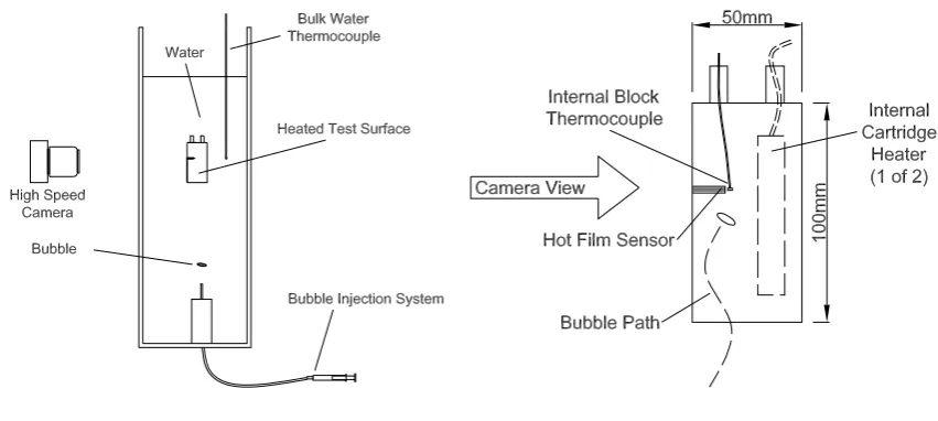
The experimental apparatus facilitates the simultaneous measurement of heat flux and temperatures and the recording of bubble motion. It comprises four main components, the water tank, the bubble injection system, the instrumented test surface and the imaging system, as shown in figure 1.
(a) Test Water Tank (b) Heated Test Surface
Figure 1: Schematic of Experimental Rig
The water is contained within a test tank that is made from 10mm thick plate glass, 780mm high with a square base of side 230mm. These dimensions were selected to provide sufficient water volume for the bulk water temperature to remain substantially constant throughout tests. The bubble injection system consists of a syringe (machined to remove the tip) mounted at the base of the tank on a movable platform. Air is fed to the syringe via a rubber hose connected to a plunger. A PC controlled servo motor presses the plunger thus supplying air to the syringe providing a single bubble of repeatable size.
[image:6.595.86.512.289.480.2]block are two 535W cartridge heaters powered by a variable power source. The heated block approximates a uniform wall temperature boundary condition. Heat flux measurement is achieved using a Senflex model SF0105 hot film sensor manufactured by Tao Systems. It is flush mounted to the block 62mm from the base and 10mm from the centre line. The sensor is mounted horizontally i.e. perpendicular to the main flow direction. It consists of a very thin layer of nickel deposited on an electrically insulating substrate required for under water applications. The nickel layer is at maximum 0.2μm thick and is positioned between two 50μm thick polyimide layers. The nickel sensing element is approximately 0.1mm wide by 1.4mm long. This results in a cold resistance of approximately 14Ω.
The hot film sensor works in conjunction with a TSI (model 1053B) constant temperature anemometer. As the CTA passes current through the film it heats ohmically and heat is transferred from the film to the surroundings. The surface heat transfer rate between the sensor and the fluid flow is related to the amount of power required to maintain the film at a set temperature. The output voltage, V, of the bridge is monitored by the data acquisition system. Equations 1 to 4 below relate the heat dissipated to resistance, voltage and current.
2
I R
qdiss = film × (1)
where probe top R R V I +
= (2)
and
cable film
probe R R
R = + (3)
therefore
(
)
22 V R R R q probe top film diss × +
The hot film is maintained at a temperature of 15ºC above that of the heated block; this is required to give a significant output from the film, thus increasing the signal to noise ratio. A consequence of this is that some heat is dissipated to the block surface through conduction. In order to evaluate the heat convected to the fluid alone the film output voltage is first measured under zero convective flow conditions, i.e. when there is no temperature difference between the block and the water. Under this zero flow condition, the measured output voltage is a combination of conduction to the copper block, convection to the fluid due solely to the film overheat and radiation (negligible) to the surroundings. This acquired voltage V0 is subsequently subtracted from the voltage measured during testing. Equation 4 now becomes:
(
) (
20 2
2 V V
R R R q probe top film
diss × −
+
=
)
(5)The geometric surface area of the hot film is given by the manufacturer to be 1.5 x 10⁻⁷m2. Due to conduction from the hot film to its surroundings the effective surface area has been shown by Beasley and Figliola [1988] to vary significantly from this. Heat generated by the film conducts into the copper block and in effect this increases the area over which heat is transferred from the film. In order to estimate the effective surface area comparisons must be made between the heat flux measured and theoretical calculations. Thus, the local heat transfer coefficient, h, for a heated vertical plate submerged in a fluid can be calculated from natural convection theory and used in conjunction with the measured temperature difference to calculate the effective surface area. This is indicated by equation 6:
T h
q A diss
eff = Δ (6)
effective surface area for each test was found to be a factor of 5.4 times that of the geometric surface area, which is consistent with the study by Beasley and Figliola [1988].
A T-type thermocouple is mounted just beneath the surface of the block at the level of the hot film sensor to measure the block temperature. A second thermocouple is suspended in the fluid away from the block in order to measure the bulk water temperature. It is maintained at the same vertical level as the other sensors. Data acquisition for the thermocouples and hot film sensor is carried out by a National Instruments data acquisition system composed of an NISCB-68 breakout board, with cold junction compensation, connected to an NI1036-E PCI
card. This card works in conjunction with LabVIEW software, also supplied by National Instruments, used to set data acquisition frequency, display the output signals and record data. High speed photography is performed by a NAC HI-Dcam II digital camera and PCI board. Photos are acquired at 250 frames per second (fps). The camera is used in conjunction with HI-Dcam link v.3 software in order to apply camera settings and record data. Both LabVIEW and the digital camera are connected to a Thurly Thandar Instruments TGP 110, 10MHz pulse generator. Upon applying a trigger, this unit generates a pulse that starts synchronous data acquisition by the digital camera and the LabVIEW software. Data are acquired for 15 seconds at 5000Hz for the thermocouple and heat flux sensors and the camera records at 250fps. Results are presented of the time resolved convective heat transfer coefficient which
has a calculated uncertainty of 35.5%. This takes account of both fluid and block temperatures but the main contributor to the uncertainty is the effective surface area.
3. Results & Discussion
transfer, the effects of the orientation of the plane in which the bubble oscillates and the effects of bubble path proximity to the plate.
3.1 Bubble Enhanced Heat Transfer
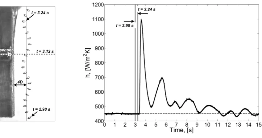
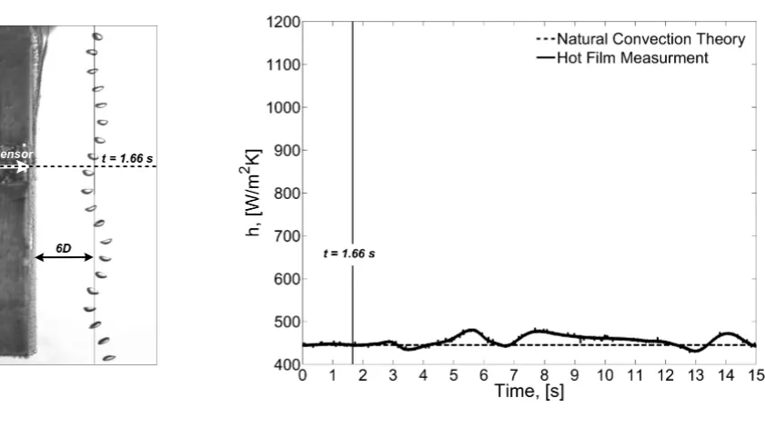
Before the bubble is injected into the tank, heat is transferred by natural convection alone. This heat transfer coefficient is obtained from the hot film sensor and has been confirmed by theoretical calculations. Images of the bubble in motion are compiled by overlapping sequential images maintaining a constant time separation of 0.02s. These images aid in understanding the bubble motion and position of the bubble in relation to heat flux and temperature measurements. In addition, the bubble is seen to oscillate at a frequency of approximately 8Hz which is comparable with Saffman, [1956].
[image:10.595.90.515.358.582.2](a) Bubble Path (b) Convective Heat Transfer Coefficient
Figure 2: Transient Evolution of Bubble Position and Surface Heat Transfer, x/D = 4
the bottom of the block and the convective heat transfer coefficient is measured as 450W/m2K. The temperature difference between the bulk water and block is 15.9ºC which yields a theoretical natural convection heat transfer coefficient very similar to the measured value, as indicated in figure 2 (b).
3.2 Effects of Bubble Orientation
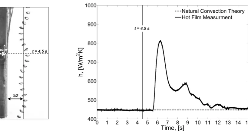
When the bubble rises through the tank it oscillates in the characteristic pattern for bubbles of this size range, as described by Bhaga and Weber, [1981]. The plane in which it oscillates doesn't generally change as the bubble rises i.e. it remains at the same angle to the heated surface as documented by Ellingsen and Risso [2001], described as the principal plane of oscillation. It can be seen that the plane in which the bubble oscillates has a dramatic effect on heat transfer enhancement. Figure 3 (a) shows a bubble oscillating in a plane normal (at an angle of 90º) to the heated surface and figure 4 (a) shows a bubble oscillating in a plane parallel (i.e. 0º) to the surface.
[image:12.595.99.509.329.558.2](a) Bubble Path (b) Convective Heat Transfer Coefficient
Figure 3: Transient Evolution of Bubble Position and Surface Heat Transfer, x/D = 5, 90°
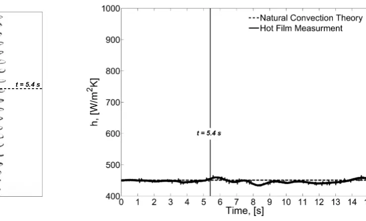
(a) Bubble Path (b) Convective Heat Transfer Coefficient
Figure 4: Transient Evolution of Bubble Position and Surface Heat Transfer, x/D = 5, 0°
A dramatic difference in the heat transfer can be seen between the two tests. This indicates that the mixing caused by the bubble has a direction associated with it. In the case where the bubble oscillates parallel to the block surface, the turbulent fluid motion appears to remain substantially within the same plane as it oscillates. The turbulent fluid motion never reaches the block where the sensor is located and therefore no increase in heat flux is seen. It is clear that in order to maximise the positive effects of the bubble on heat transfer it must oscillate in a plane perpendicular to the face of the heated block. Further research is still required in the field of flow visualisation and bubble imagery in order to better understand the fluid motion around the bubble and in its wake. It would be advantageous to simultaneously record the motion of the bubble from two angles orientated perpendicular to each other in order to obtain the position of the bubble in three dimensions. Understanding this is essential to understanding the mechanisms behind heat transfer enhancement.
makes it difficult to determine the bubble plane of oscillation relative to the block and it is also hard to establish whether the bubble passes directly in front of the hot film sensor. If the bubble plane of oscillation is not normal to the plate or if the bubble passes to the side, rather than in front of, the hot film sensor, it can lead to a lower enhancement effect recorded by the hot film sensor. The influence of the plane of oscillation has been addressed in this section while maintaining a constant mean distance from the plate for a similar sized bubble that passes directly in front of the hot film sensor.
3.3 Effects of Bubble Proximity to Plate
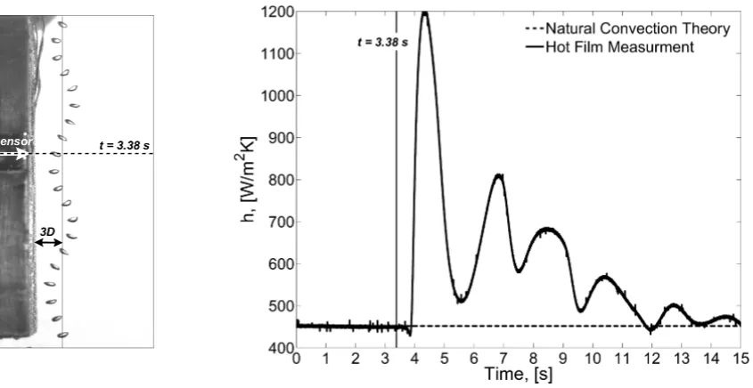
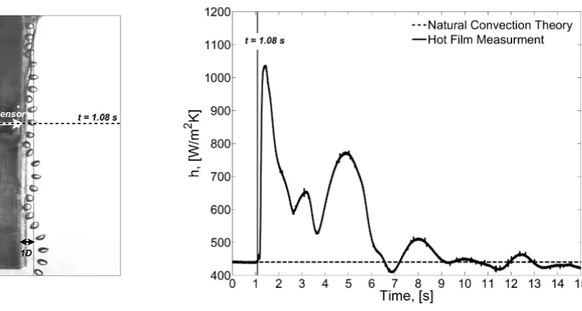
The distance from the bubble path to the block has a major influence on heat transfer. Images of the bubble path and heat transfer timelines are presented in this section for bubbles passing at distances of 6D, 3D and 1D from the heated surface. The effects of bubble proximity are presented in figures 5 to 7 for tests in which, subject to the constraints of the experimental set-up, the bubble passes directly in front of the sensor and the plane of oscillation is normal to the surface.
[image:14.595.93.514.464.705.2](a) Bubble Path (b) Convective Heat Transfer Coefficient
(a) Bubble Path (b) Convective Heat Transfer Coefficient
Figure 6: Transient Evolution of Bubble Position and Surface Heat Transfer
(a) Bubble Path (b) Convective Heat Transfer Coefficient
Figure 7: Transient Evolution of Bubble Position and Surface Heat Transfer, x/D = 1
Figure 7 (a) & (b) illustrate the bubble path and transient evolution of heat transfer for a rising bubble path one bubble diameter from the heated surface. At a distance of 1D, the bubble can be seen to impact on the heated block and skim along its face. The bubble now acts like a bluff body disturbing the thermal boundary layer directly as it travels through it rather than relying on the indirect effect of the wake to increase heat flux (although the lasting effects are still attributed to the bubble wake). This explains why the effects on heat flux are seen approximately 0.03s before the bubble reaches the level of the hot film sensor (t = 1.08s). There is a dramatic increase in the heat flux, rising in a sharp peak from the natural
mechanism by which the bubble disturbs the thermal boundary layer (i.e. the bubble itself disturbs the thermal plume rather than the bubble wake).
4. Conclusions
This paper reports on an experimental investigation of the dynamics of a rising bubble and its influence on heat transfer from a vertical heated plate. Heat flux measurements taken using a hot film sensor have shown that the rising bubble and its wake can have a significant effect on heat transfer. When the bubble rises close to the plate (within approximately 5mm) it acts like a bluff body, displacing the heated fluid, increasing local mixing and allowing cooler water to move in. For bubbles that rise further from the plate, it is the wake of the bubble that enhances heat transfer, the level of which is dependent on two parameters. Firstly, the closer the bubble is, the higher the increase in heat flux. Secondly, the orientation of the plane in which the bubble oscillates has a dramatic effect on enhancement. It is observed that when the bubble oscillates in a plane parallel to the heated plate, little positive effect on heat flux is seen, whereas, for the same sized bubble at a similar mean distance but oscillating in a plane perpendicular to the block face, a dramatic increase in heat flux is observed. It is also observed that a time delay exists between when the bubble passes the block and when the wake impacts; this is related to the displacement between the bubble path and plate. Further study is required in the field of flow visualisation in order to fully understand the phenomenon that occurs here.
Acknowledgment
Nomenclature
Symbol Description Units
Aeff Effective surface area of sensor [m2]
D Equivalent bubble diameter [m]
V Voltage [V ]
h Convective heat transfer coefficient [W/m2K]
I Current [A]
q Rate of heat transfer [W]
R Resistance [Ω]
t Time [s]
T Temperature [K]
References
Atmane, M.A. and Murray, D.B., (2001) Bubble dynamics in nucleate boiling around a cylinder, Experimental Heat Transfer, Fluid Mechanics, and Thermodynamics, Pisa, Italy, pp. 1343-1348.
Beasley, D.E. and Figliola, R.S., (1988) A generalised analysis of a local heat flux probe, Journal of Physics E: Scientific Instrumentation, Vol. 21, pp. 316-322.
Bhaga, D. and Weber, M.E., (1981) Bubbles in viscous liquids: shapes, wakes and velocities, Journal of Fluid Mechanics, Vol. 105, pp. 61-85.
Brücker, C., (1999) Structure and dynamics of the wake of bubbles and its relevance for bubble interaction, Physics of Fluids, Vol. 11, pp. 1781-1796.
Cornwell, K. and Grant, I.A., (1998) Heat transfer to bubbles under a horizontal tube, International Journal of Heat and Mass Transfer, Vol. 41, pp. 1189-1197.
Delauré, Y.M.C., Chan, V.S.S. and Murray, D.B., (2003) A simultaneous PIV and heat transfer study of bubble interaction with free convection flow, Experimental Thermal and Fluid Science, Vol. 27, pp. 911-926.
Ellingsen, K. and Risso, F., (2001) On the rise of an ellipsoidal bubble in water: oscillatory paths and liquid-induced velocity, Journal of Fluid Mechanics, Vol. 440, pp. 235-268. Manickam, S. and Dhir, V., (2003) Holographic interferometric study of heat transfer
associated with a single vapor bubble sliding along a downward-facing heater surface, ASME Summer Heat Transfer Conference, Las Vegas, Nevada.
Qiu, D. and Dhir, V.K., (2002) Experimental study of flow pattern and heat transfer associated with a bubble sliding on downward facing inclined surfaces, Experimental Thermal and Fluid Science, Vol. 26, pp. 605-616.
Thorncroft, G.E. and Klausner, J.F., (1999) The influence of vapour bubble sliding on forced convection boiling heat transfer, ASME Journal of Heat Transfer, Vol. 121, pp. 73-79. Yan, Y., Kenning, D. and Cornwell, K., (1997) Sliding and sticking vapour bubbles under