Analysis of Shunt Active Filter with PI, Fractional Pi
Controller and ANN based Controller
Munazama Ali
Dept. of EEE Islamic university
Kashmir, India
Dheeraj Joshi,
PhD Dept. of EEE Delhi Technical University,New Delhi, India
ABSTRACT
Non-linear loads connected in electrical power system leads to distortions in the source current waveform. One solution to improve power quality is the use of Shunt active power filter which are able to correct both the harmonics and the unbalance in the load current. In any active power filter system, performance of compensation of harmonics largely depends upon the algorithm adopted as the control methods are responsible for generating the reference currents which are used to trigger the voltage source inverters. In this paper, Hysteresis-band PWM is used as control strategy in which generated reference sin current wave is compared with actual current wave and the desired output of hysteresis-band PWM is applied to trigger the voltage source inverter. In this paper Shunt active power filter has been implemented in MATLAB using three different controllers in order to reduce current harmonics on load side. As the performance of three controllers Fractional PI, PI and ANN Controller have been simulated it has been concluded that in any system PI controller requires precise linear mathematical models, which are difficult to obtain and fails to perform satisfactorily under parameter variation, load disturbances, on the other hand Fractional PI Controller performs satisfactorily for the same parameter variation. Whereas ANN Controller is considered to be the new tool in the design of Shunt active power filter control circuit as it provides high speed recognition, learning ability etc.
Keywords
Shunt Active Power Filter (SAPF), Passive filters, PI Controller, Fractional PI Controller, Ann Controller, and Hysteresis current control.
1
INTRODUCTION
Nowadays with the use of wider range of non-linear loads such as arc furnace, computer appliances, variable speed drives etc., draw non-sinusoidal currents. When source is connected to linear load there is no effect on source and system is said to be stable also when the source is connected to non-linear load, load will produce harmonics on load side due to these harmonics load will become nonlinear. This fact has led to more stringent requirement regarding power quality which includes the search for solution of such problems. To mitigate these harmonics, different solutions are proposed and used by researcher such as line conditioners, passive filters and active filters, etc. Traditional solution to these problems are based on passive filters due to their easy design, low cost but having some disadvantages such as large in size, fixed compensation and resonance problems could not be used for overall compensation to overcome these disadvantages Active power filters has been introduced. Active power filters are dynamic performance devices which are designed to improve overall performance by eliminating current harmonics and
provide reactive power requirement. In order to reduce non-sinusoidal load currents, Shunt active power filter to be connected in parallel with the non-linear load based on sensing harmonics and reactive power requirement of the non-linear load.
In the case of current harmonics the Shunt active power filter appears as the best dynamic solution for harmonic compensation. The principle operation of Shunt active power filter is to generate compensating currents into the power system for cancelling the current harmonics contained in the non-linear load current. This will result in sinusoidal line currents and unity power factor in the input power. This paper offers a good way to optimize the performance of Shunt active power filter [1]. By using three different controllers Fractional PI, PI and ANN Controllers. The overall dynamic performance of the Shunt active power filter has been increased. In this paper, a multi-range Fractional-order repetitive control scheme proposed for enhancing Active Power Filter(APF) performance where is assumed tovary in a range between 0.1 to 1. Depending on the values of the order ʎ, and phase and gain margin, different stability regions have been obtained. It has been seen, Fractional order pi controller is less sensitivity to parameter variation than classical PI controller, as the Fractional order PI controller makes use of fractional order derivatives and integrals because of which overall dynamic performance is improved [2]. The performance of the proposed controllers has been investigated, compared and analysed under different testing scenario and different simulation results are implemented. All the three controller simulation results illustrates that the proposed technique ANN Controller are more promising than Fractional PI and PI Controller because of its high speed recognition, learning ability and ability to adapt themselves in any system.
2
FRACTIONAL ORDER SYSTEM
Fractional order calculus is an area where the mathematics deals with derivatives and integrals from non-integral orders. The Fractional order system is the direct extension of classical integral order system. The fractional order transfer function of a single variable system can be defined as:
G(s) =
Where are real numbers and the order of the numerator and denominator can also be real number.
other hand, the fractional calculus is getting much more attention in the field of control system engineering due to its potential and significant importance.
Fractional order has number of advantages over classical pi controllers as:
For parameter variation in system, fractional order pi controller is less sensitive than a classical pi controller. The fractional order pi controller makes use of fractional order derivatives and integrals that gives improved performance compared to the classical controller.
Fractional order controller have two extra variables to tune. This provides extra degree of freedom to the dynamic properties of fractional order system.
It has been observed, when is used to substitute for the variable‘s’ in the Fractional order transfer function model, the frequency Ga(j can be easily evaluated.
Recent research trends in Fractional order controller are looking towards using fuzzy with Fractional order control scheme to improve the control performances. The rule base fuzzy set theory provides more flexibility in designing complex industrial control system [4].
3
SHUNT ACTIVE POWER FILTER
The Shunt active power filter was a recently developed piece of equipment for simultaneously delivering the compensating current to suppress the current harmonics on the ac side to make mains current sinusoidal. The active power filter is connected in parallel with nonlinear load. Active Power filters have wide application in modern electrical distribution system for eliminating the harmonics associated with it. Shunt active power filter (SAPF) is one of power filters which have better dynamic performance and it needs an accurate control algorithm that provides robust performance [5]. The control methods are responsible for generating reference currents which are used to trigger the Voltage Source Inverters.
It has been used to:
Eliminate current harmonics
Balance and regulate terminal voltage of load/line. Reduce negative sequence voltage.
Installed by electric utilities to compensate voltage harmonics and swamp out harmonic propagation caused by resonance with line impedances and passive shunt compensator.
3.1
Basic Compensation Principle
The active power filter is controlled to deliver the compensating current if from/to the load on the AC side and reactive power flow from/to the source there by making the source current in phase with source voltage.
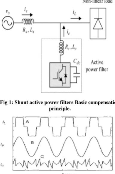
[image:2.595.328.521.78.368.2]Figure 1 shows basic compensation principle of the shunt active power filter. It is controlled to draw/ supply a compensating current from/ to the utility, so that it cancels current harmonics on the AC side, and makes the source current in phase with the source voltage.
Fig 1: Shunt active power filters Basic compensation principle.
Fig 2: Shunt active power filter (SAPF)-Shapes of load, source and desired filter current wave forms.
Figure2 above shows the different waveforms. Curve A represents load current waveform, curve B is desired load current and curve C shows the compensating current injected by active power filter contains all the harmonics to make mains current sinusoidal.
3.2
Estimation of Reference Source Current
From figure 1, the instantaneous current can be written as
= - (3.1)
Source voltage is given as:
= (3.2)
If a non-linear load has applied, then the load current will have a fundamental component and harmonic components which can be represented by
= )
= + ) (3.3)
The instantaneous load power can be given as
*
t*+ sin t*cos t*sin + sin * ( n t+ )
+ (t) + (t) (3.4)
From (3.4), the real (fundamental) power drawn by the load is
(t) = t*cos = (t)* (t) (3.5)
(t) = (t) / (t) = cos sin t = sin t (3.6)
Where = cos
There are also some switching losses in the PWM converter, and hence the utility must supply a small overhead for the capacitor leakage and converter switching losses in addition to the real power of the load. The total peak current supplied by the source is therefore
= + (3.7)
If the active filter provide total reactive and harmonic power, then (t) will be in phase with the utility voltage and purely sinusoidal. At this time, the active filter must provide following compensation current:
= (t) - (t)
Hence, for accurate and instantaneous compensation of reactive and harmonic power it is necessary to estimate, i.e. fundamental component of the load current as the reference current.
3.3
Estimation of The Reference Source
Current
The peak value of the reference current can be estimated by controlling DC side capacitor voltage. Ideal compensation requires the mains current to be sinusoidal and in phase with the source voltage, irrespective of the load current nature. The desired source currents, after compensation, can be given as
* = sin t
* = sin t
* = sin t+120
Where = ( cos + ) amplitude of the desired source current, while the phase angle can be obtained from the source voltage. Hence, waveform and phases of source currents are known, and only the magnitudes of the source currents need to be determined. This peak value of the reference current has estimated by regulating DC side capacitor voltage of PWM converter. This capacitor voltage is compared with a reference value and the error is processed in a Fractional PI, PI or ANN controller. The output of the Fractional PI, PI or ANN controller has been considered as the amplitude of the desired source current, and the reference currents are estimated by multiplying this peak value with unit sine vectors in phase with the source voltages parameters.
4
ANN CONTROLLER SCHEME
Recently Ann Neural Network have attracted much different applications including Shunt Active power filter. As performance of Shunt active power filter is determined by the accuracy and precision of harmonic extraction different controllers has been used to improve its overall performance. Generally conventional PI controller is used to regulate the dc-link voltage. But due to its limitations ANN Controller has been used because of unique ability such as high speed recognition, learning ability and ability to adapt themselves in any system. Here integration of Ann based predictive and adaptive control techniques are used to generate gating pulses for voltage source inverter [6]. The Artificial Neural Networks (ANNs) has been systematically applied to the electrical engineering. This method is considered to be a new tool to design SAPF control circuits. The ANN presents two principal characteristics. It’s not necessary to establish
specific input-output relationships but they are formulated through a learning process. Moreover, the parallel computing architecture increases the system speed and reliability. In this paper, a new SAPF control method based on ANNs has been presented. Load voltages and currents are sensed, the control blocks calculates the power circuit control signals from the reference compensation currents, and the power circuit injects the compensation current to power system.
5
PERFORMANCE EVALUATION
[image:3.595.319.538.326.470.2]The simulation is carried out with the three phase three wire system with non-linear load. Here the diode rectifier is used as non-linear load. The Fig.5 shows the three phase current waveform without any filter where THD (Total Harmonic Distortion) is very high. Therefore different controllers ANN controller, Fractional PI and PI Controller has been used and simulated in MATLAB to reduce the overall THD to a desired value. The complete active power filter system is composed mainly of the three-phase source, a nonlinear load, a voltage source PWM converter, and a controller. All these components are modelled separately with different controllers, integrated and then simulated to determine the overall performance of system. In this paper SAPF model is proposed, shown in figure 3.
Fig 3: Simulation model of Shunt Active Power Filter (SAPF).
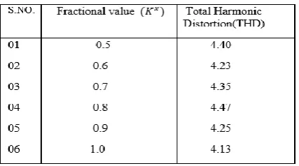
In this paper, a multi-range Fractional-order repetitive control scheme proposed for enhancing Shunt Active Power Filter(APF) performance where is assumed to vary in a range between 0.1 to 1. Depending on the values of the order ʎ, and phase and gain margin, different stability regions have been obtained.
[image:3.595.323.537.594.713.2]Table 2. THD using Fractional PI Controller and ANN Controller at different fractional values.
Table 3. THD with different values of various loads using ANN Contoller.
[image:4.595.62.272.98.245.2]The SAPF is switched to the system at 0.2 sec. The responses before and after switching can be easily distinguished from the waveform and THD values given in the figures below.
Fig 4: waveform of Three phase source currents without
[image:4.595.315.559.318.598.2]active power filter.
Fig 5: Harmonic spectrum without active filter.
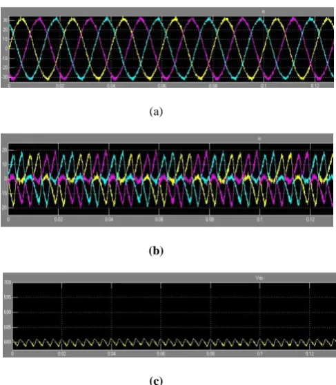
(a)
(b)
(c)
[image:4.595.54.292.477.542.2]Fig 7: Total Harmonic distortion with PI Controller.
(a)
(b)
[image:5.595.316.552.71.277.2](c)
Fig 8. Three phase balanced (a) Source current (b)SAPF Injected current(c)DC link voltage with Ann Controller.
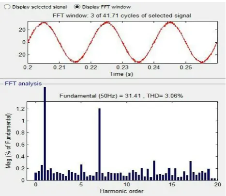
[image:5.595.54.299.298.581.2]Fig 9: Total Harmonic distortion with Ann controller.
Fig 10: THD with Fractional PI Controller.
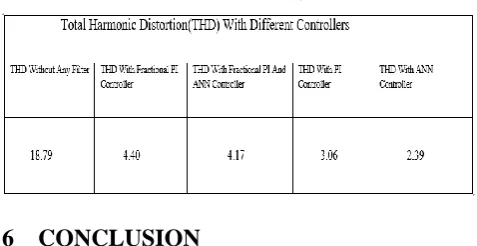
[image:5.595.320.540.307.731.2]Table 4.Thd using Different Controllers (Fractional PI, PI and ANN Controller).
6
CONCLUSION
The power quality management is the main problem that the industries are facing today. As the number of non-linear equipment’s are increased day to day the quantity of harmonics are increased due to which overall performance of the system are degrading as it becomes major concern to reduce the effect of these harmonics. In this paper we clearly calculate the THD with different controllers.
In the paper three controllers are developed and verified for the three phase three wire systems. Even though all the presented controllers are capable of compensating line current harmonics in 3 phase 3-wire systems, it can be seen that the ANN and Fractional PI controller has a better dynamic performance than the conventional PI controller. Hysteresis current control provides quick response as it generates desired gate pulses for voltage source inverter. It can also be seen that the DC voltage regulation system is a stable. The SAPF is observed to eliminate the harmonic and reactive components of load current resulting in sinusoidal and unity power-factor source currents. It is observed that the source current remains below the load current even during transient conditions. The SAPF enhances the system performance because the source need not process the harmonic and reactive power demanded by the load. Among many approaches for determining the SAPF reference compensation currents, one of the main streams is to maintain sinusoidal source currents supplying average real power to the load. With the use of sinusoidal source current strategy, it is proved that the SAPF can have better performance than other strategies.
7
REFERENCES
[1] N. ramchandra, M.kalyanchakravarthi, “neural network based unified power quality conditioners”, International journal of Modern Engineering Research (IJMER) www.ijmer.com Vol.2, Issue. 1, jan-Feb 2012 pp-359-365ISSN: 2249-6645, 2012.
[2] Ying Luo and YangQuan Chen, “Fractional order [PD] controller for robust motion control: Tuning procedure and validation”, 2009 american control conf., 2009, pp. 1412-1417.
[3] Arijit Biswas, Swagatum Das, Ajith Abraham and Sambarta Dasgupta, “Design of fractional-order
controllers with an improved differential evolution”, Engineering Applications of Artificial Intelligence, Volume 22, Issue 2, pp. 343-350, March 2009.
[4] Ivo Petras, Fractional-order nonlinear systems: modelling, Analysis and Simulation, Springer, 2010.
[5] Yash Pal , A. Swarup , and Bhim Singh, “Applications of APF for Power Quality Improvement” IEEE
Transactions On Power Systems conference, December, 2010.
[6] Munazama Ali,arminder kaur and Abdul hamid bhat “comparative Analysis of shunt active power filter with pi and Ann controller”, International journal of computer applications(1-6, August) 2016.
[7] Elsa Susan Daniel and G.Abirami “Selective Harmonic Elimination Using Shunt Hybrid Active Power Filters Operating At Different Switching Frequencies” International Journal of Innovative Research In Electrical & Electronics, Instrumentation and Control Engineering Vol. 1, Issue 1, April 2013
[8] Chennai Salim and Benachaiba Mohamed Toufik,“ Three-phase three-level (NPC) Shunt Active PoweFilter performance based pwm and Ann Controllers for Harmonic Current compensation”,International journal on Electrical Engineering and Informatics volume6, 2014.
[9] Aziz Boukadoun, Tahar Bahi, Abla Bouguerne, Youcef Soufi, Sofiane OUdine, “ Hysteresis Band Current Fuzzy Logic Control for active power filter”, Eighth International conference and exhibition on Ecological Vehicles and Renewable Energies (EVER), 2013.
[10] T. Liu and D. Wang, “Parallel Structure Fractional Repetitive Control for PWM Inverters,” IEEE Trans. Ind. Electronic., Vol. PP, no. 99, pp. 1-1, 2015.
[11] T.Mahalekshmi “Current Harmonic Compensation and Power Factor Improvement by Hybrid Shunt Active Power Filter” International Journal of Computer Applications (0975 – 8887) Volume 4 – No.3, July 2010.
[12] Brahim Berbaoui, Chellali Benachaiba and rachid Dehini, “ Design of optimal PI controller for shunt Active Power Filter using particle Swarm Optimization”, Quatrieme Conference international surle genie Electrique CIGE’ 10, University deBechar Algerie, 2010.
[13] Rachid dechini, Abdesselam bassou,Brahimferdu, “ The harmonics detection method based on neural network applied to harmonics compensation”, International journal of engineering, science and technology, vol.2 , pp.258-267, 2010.
[14] S. Jain, P. Agarwal, and H. O. Gupta, “Design simulation and experimental investigations on a shunt active power filter for harmonics and reactive power compensation,” Electrical Power Components and Systems, vol. 32, no. 7, Jul. 2003, pp. 671–692.
[15] F. Zahira, a. peer Fatima, “A technical survey on control strategies of active filter for harmonic suppression”,ICCTS, 2012.
[16] B. Singh, V. Verma, and J. Solanki, “Neural network-based selective compensation of current quality problems in distribution system,” IEEE Trans. Ind. Electron., vol. 54, no. 1, pp. 53–60, Feb. 2007.
[17] Simulink–Model-Based and System-Based Design, Modelling, Simulation, Implementation version 5, TheMathnWorks, July 2002.
[19]A. E. Emanuel, “Summary of IEEE Standard 1459: definitions for the measurement of electric power quantities under sinusoidal, non-sinusoidal, balanced, or unbalanced conditions,” IEEE Trans. Ind. Appl., vol. 40, no. 3, pp. 869–876, May/Jun. 2004.
[20]Metin Kesler and Engin Ozdemir, “Synchronous-Reference Frame-Based Control Method for SAPFUnder Unbalanced and Distorted Load Conditios”, IEEE transactions on industrial electronics, VOL. 58, NO. 9, SEPTEMBER 2011.
[21] Z-X Zou, K. Wang, and M. Cheng, “Frequency adaptive Fractional-Order Repetitive Control of Shunt Active power Filter,” IEEE Trans. Ind. Electronic., Vol. 62, no.3, pp. 1659-1668, Mar. 5015.