http://www.scirp.org/journal/jectc ISSN Online: 2162-6170 ISSN Print: 2162-6162
DOI: 10.4236/jectc.2018.81001 Mar. 30, 2018 1 Journal of Electronics Cooling and Thermal Control
Proposal of Functional Thermal
Control Systems for High-Power
Micro-Satellite and Its
Demonstration under Thermal
Vacuum Condition
Ai Ueno
*, Kohei Yamada, Kikuko Miyata, Hosei Nagano
Nagoya University, Nagoya-shi, Japan
Abstract
In previous years, several high-power micro-satellites below ~100 kg have been developed for high-functional spacecraft. This paper proposes a func-tional and high-power thermal control system with no power supply and a simple configuration for micro-satellite: 100 W, 3 U. The proposed system consists of a heat storage panel (HSP) with pitch type CFRP (Carbon Fiber Reinforced Polymer), a micro loop heat pipe (m-LHP) and a flexible re-deployable radiator (FRDR) as an active thermal control system. The aim of this research is to try not only to verify the thermal control devices, but also to perform a water phase change experiment as a payload using an electric power generation of 100 W in space environment. In this paper, the basic de-sign of the satellite, the analysis of the feasibility by the thermal mathematical model, and the fabrication of thermal test model including water phase chamber are reported. The main results of thermal analysis as feasibility veri-fication showed that the paddles could absorb the thermal energy up to 97 W at the solar input of 180 W, and the operating temperature of bus equipment became within the allowable temperature range (0˚C - 40˚C). At thermal va-cuum test, the difference between the analysis and the experiment for the temperature history of water due to the discordance for the value of thermal conductance was discussed.
Keywords
Micro-Satellite, Thermal Control, Heat Storage Panel, Loop Heat Pipe, Flexible Re-Deployable Radiator
How to cite this paper: Ueno, A., Yamada, K., Miyata, K. and Nagano, H. (2018) Pro-posal of Functional Thermal Control Sys-tems for High-Power Micro-Satellite and Its Demonstration under Thermal Vacuum Condition. Journal of Electronics Cooling and Thermal Control, 8, 1-17.
https://doi.org/10.4236/jectc.2018.81001
Received: February 18, 2018 Accepted: March 27, 2018 Published: March 30, 2018
Copyright © 2018 by authors and Scientific Research Publishing Inc. This work is licensed under the Creative Commons Attribution International License (CC BY 4.0).
DOI: 10.4236/jectc.2018.81001 2 Journal of Electronics Cooling and Thermal Control
1. Introduction
In recent years, high-power micro-satellites below ~100 kg have been under fo-cus [1] and their usability has been proved. A large number of micro-satellites are developed in accordance with the standards of CubeSat which is defined as the satellite with the weight of 1.33 kg or less per 1 U (10 cm × 10 cm × 10 cm). CubeSats have extended their mission capabilities and often their mission is comparable to the mission of bigger satellites. For example, Planet Labs Inc. (USA) launched over twenty 3 U satellites named Dove offering the service of providing Earth images to their customers, their mission focusing on Earth ob-servation [1] [2]. NASA has developed 6 U CubeSat: Mars Cube One as mars probe and their CubeSats aim to advance the mission level beyond the earth’s orbit [3].
Due to the development of high functional micro-satellites, high-power mi-cro-satellites whose benchmark is 100 W, 3 U, have been demanded. Miltech Co. (USA) has developed High-Power CubeSat Concept for 3 U satellite [4]. Tether Inc. (USA) proposed Power Cube which can carry out electric propulsion for 80 W, 3 U satellite [4].
For the thermal design of micro-satellite, especially for CubeSat, there are specific challenges which are not considered for a large-scale satellite due to its physical limitations. Generally, passive control is applied as thermal control for the micro-satellites of small-power consumption, because the priority of thermal design is lower than other subsystems such as propulsion subsystem etc. How-ever, their passive thermal control methods are not suitable for high-power mi-cro-satellites.
Under such a background, our final goal is to build a functional and high-power thermal control system for a 100 W, 3 U micro-satellite. The main feature of this proposed system is no power supply, a simple configuration and an active con-trol to realize variable concon-trol. In this paper, a 3 U satellite was proposed as a testbed of 100 W thermal control system with a heat storage panel (HSP), a mi-cro loop heat pipe (m-LHP) and a flexible re-deployable radiator (FRDR). To build this system, a demonstration satellite which can absorb the solar heat of 100 W was designed and the experiment of three phase changes of water was proposed as the payload using an electric power generation of 100 W. Moreover, the feasibility of the missions was verified by thermal mathematical model and the thermal test model was built for the space environment testing.
2. Proposal of Micro-Satellite with Functional Thermal
Control System
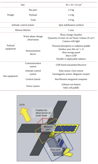
DOI: 10.4236/jectc.2018.81001 3 Journal of Electronics Cooling and Thermal Control Table 1. Specification of the proposed micro-satellite (3 U, 100 W).
Size 30 × 10 × 10 cm3
Weight
Bus part 2.5 kg
Payload 1.4 kg
Total 3.9 kg
Attitude control system Spin stabilization method
Mission lifetime 1 year
Payload equipment
Water phase change observation
Phase change chamber
(Quantity of water 24 cm3/Inner volume 29 cm3) Camera with light
Demonstration device
Thermal absorption or radiation paddle (Surface area 266 cm3 × 3)
Heat storage panel Micro LHP Flexible re-deployable radiator
Bus equipment
Communication
system UHF band transmitter/Receiver Attitude control
system Geomagnetic sensor, Magnetic torquer Solar sensor, Gyro sensor Control system Bus/Mission integrated computer
Power system Lithium-ion battery Solar cell paddle
Figure 1. Schematic view of the proposed micro-satellite.
DOI: 10.4236/jectc.2018.81001 4 Journal of Electronics Cooling and Thermal Control communication equipment et al. (the opposite side to the sun). The payload is exposed to a dynamic temperature fluctuation by solar heat of 100 W class for the water phase change experiment. On the other hand, the temperature of the bus part is minimized to keep the performance of the satellite. Therefore, in the bus part, the active thermal control with the functional thermal system is de-manded.
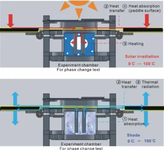
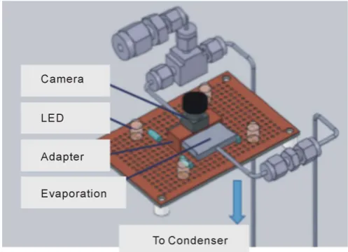
[image:4.595.209.537.402.701.2]Figure 2 shows a cross section view of the mission part to explain the me-chanism of phase change experiment. During the sunlight, the mission part is heated by absorption of solar heat with the thermal absorption or radiation pad-dle. The surface for heat absorption is the graphite sheet (surface: KGS, Kaneka Co. and substrate: CFRP, Nippon Graphite Fiber Co., Ltd.) which has the ad-vantages not only of thermal conductivity (950 W/(mK) at 100˚C) but also of specific flexibility. Thus, this graphite sheet works as heat transport path without preventing the paddle from expansion and storage. The heat from the sun on the paddle is transported to the aluminum container in the center of the mission part via the graphite sheet. During the eclipse, the mission part is cooled only by thermal radiation to deep space from graphite sheet. For an efficient thermal radiation and absorption, the surface of the graphite sheet is coated to optimize the optical properties of the surface: the solar absorptance α and the emittance ε. Thus the payload can maximize the temperature fluctuation (0˚C - 100˚C) in Earth orbit to achieve the water phase change.
DOI: 10.4236/jectc.2018.81001 5 Journal of Electronics Cooling and Thermal Control
2.1. HSP: Heat Storage Panel
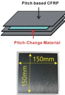
HSP is the heat storage material which consists of a pitch type CFRP (Carbon Fiber Reinforced Polymer) and PCM (Phase-Change Material) [5]. The aim of HSP is smoothing of temperature from the devices by increasing the apparent heat capacity using the latent heat of PCM. PCM storage the heat at the temper-ature rising, on the other hand, PCM release the heat at the tempertemper-ature de-creasing by using the latent heat due to the phase change. PCM has a disadvan-tage of low thermal conductivity. Thus, high thermal conductivity as well as strength is demanded for the component enclosing PCM. Previous researches of HSP with PCM for satellite are reported and aluminum alloy are used for their components for PCM [6] [7] [8]. In this research, the pitch type CFRP is used for the component enclosing PCM. The pitch type CFRP has an advantage of high thermal conductivity of 347 W/(mK) in the direction of a fiber axis. There-fore, HSP can be applied not only for the heat storage panel, but also for the heat sink or structure material. Their multi-functions of HSP are superiority to mi-cro-satellite under severe restriction on size and mass.
2.2. m-LHP: Micro Loop Heat Pipe
The m-LHP is a heat transport device which is activated by using capillary force [9] [10] [11]. The LHP consists of an evaporator with porous wick, a compensa-tion chamber (CC), a vapor line, a condenser, and a liquid line. The CC has a function as a reservoir of liquid. A LHP is a two-phase heat transfer device that utilizes the evaporation and condensation of a working fluid to transfer heat, and the capillary forces developed in fine porous wicks to circulate the fluid. The effective thermal conductivity of LHP can be relatively high due to latent heat transport. Furthermore, the LHP has been expected as a next-generation heat transport device, because the LHP can drive without power supply and have high flexibility of design. The LHPs have been mounted in large scale satellites like ETS-VIII, etc. [9] [12]. However, there has never been reported for LHP to apply for micro-satellite. In our group, the m-LHP has been developed especially for mobile devices [11]. The characteristics of proposed m-LHP are the evapo-rator size of 20 × 20 × t 3 mm as a flat type structure and a one-way transport length of 200 mm with polytetrafluoroethylene (PTFE) as the wick. In addition to the advantage of size of m-LHP for small satellite, the proposed m-LHP can drive under microgravity. Because the m-LHP integrates the evaporator and the CC as a combined unit, the working fluid can be supplied through the wick con-stantly. Thus the m-LHP is suitable for micro-satellite.
2.3. FRDR: Flexible Re-Deployable Radiator
DOI: 10.4236/jectc.2018.81001 6 Journal of Electronics Cooling and Thermal Control [13] [14] [15]. The features of the radiator are as follows: 1) the radiation area can be expanded more than the surface area even after the launch and orbit in-sertion; and 2) Graphite Sheet (GS) which has high thermal conductivity, lightweight, and flexibility is used for the integrated parts between the main body and the deployable part. Thus, the radiation area also becomes a path for heat transfer.
3. Design and Verification
3.1. Design of Micro-Satellite
[image:6.595.266.480.451.693.2]The biggest challenge for the micro-satellite is to keep the temperature of the bus part around room temperature, though the payload is facing a dynamic temper-ature fluctuation. The thermal control system for this micro-satellite involves two main concepts: 1) At the payload, the thermal environment is adapted for the water phase change experiment by controlling the surface property of the high thermal conductivity material; and 2) At the bus part, the temperature fluctuation is minimized by the active use of the functional thermal devices without power supply such as heater etc.
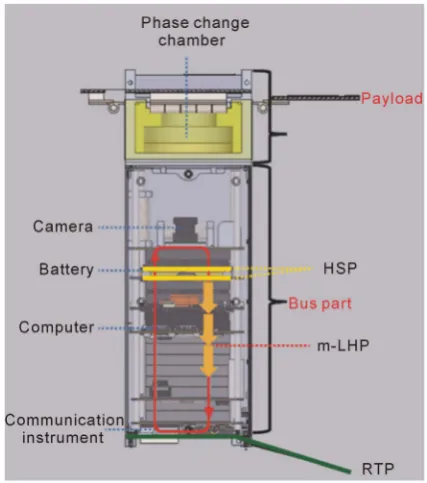
Figure 3 shows the configuration of the proposed micro-satellite based on the above design concept. The payload is mounted on the side facing the sun and the camera for water phase change experiment is mounted on the most side of the sun. The battery is equipped in the center of the satellite because it is a heavy component and it has a narrow allowable temperature range. The communica-tion instruments which have a large amount of exhaust heat are equipped on the side of the radiator (the non-illuminated side).
DOI: 10.4236/jectc.2018.81001 7 Journal of Electronics Cooling and Thermal Control The design details of each functional device are shown below. The battery which has the narrowest allowable temperature range is controlled with the heat storage panel (HSP) as shown in Figure 4. The HSP can buffer the dynamic temperature fluctuation by increasing the apparent heat capacity. The design of the HSP is based on the HSP of Hodoyoshi 4 [5]. The HSP consists of side panels (7 mm thick) and PCM (11 mm thick). In this study, the configuration of HSP and the material of PCM were modified due to the difference in the application temperature range and the mounted area. Hexadecane (C16H34) was selected as the PCM because the phase change point (melting point 18˚C) is almost the same as the middle point of the allowable temperature range for the application object. The size of HSP is 96 mm × 85 mm based on 3 U standard. From the analysis of the satellite thermal mathematical model (below for the details), the temperature fluctuation to control with the HSP becomes 20˚C. Therefore, the required amount of heat storage is calculated as 970 J from heat capacity of bat-tery 48.5 J/ K. In this satellite, two HSPs are applied with heat storage 572 J per HSP.
[image:7.595.305.433.518.705.2]The camera, whose temperature becomes high during the sunlight, is con-trolled with the m-LHP as shown in Figure 5. In the sunlight, the camera mod-ule is influenced by the thermal input of its own heat generation of 4.0 W and of the thermal radiation of 4.5 W. This condition is supposed to be applied under the worst-case assumption that the temperature of camera module is 20˚C and the temperature of phase change chamber is 150˚C. Thus, the maximum heat transport quantity of the m-LHP becomes 10 W which includes the margins of 20% to the against maximum thermal input 8.5 W. Meanwhile, during the ec-lipse, the minimum start-up heat load corresponds to the own heat generation 4.0 W from the camera module. In this research, acetone is selected as the working fluid for the m-LHP because of a relatively low boiling point matching with the working temperature 55˚C and the allowable temperature of the camera module 70˚C.
DOI: 10.4236/jectc.2018.81001 8 Journal of Electronics Cooling and Thermal Control Figure 5. Micro loop heat pipe for the cooling of the camera module.
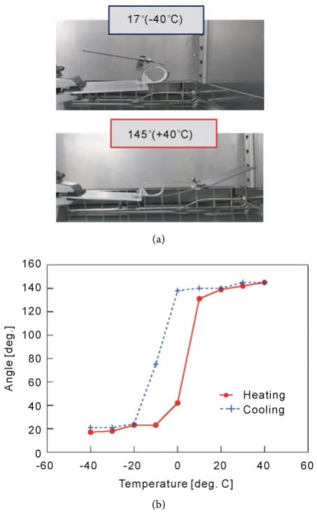
Figure 6(a) shows a flexible re-deployable radiator to waste the heat from the m-LHP and from the communication instruments. The target performance is determined so that the size of storage is under 95 mm × 110 mm, and the max-imum radiation amount is 11.8 W at the temperature of fin of 55˚C. The fin consists of graphite sheet (size 300 mm × 75 mm, thickness 40 μm × 10 layers, Kaneka Co.). The surface of the flexible re-deployable radiator is silver deposi-tion Teflon (125 μm thick) which has the solar absorptance α = 0.22 and the to-tal hemispherical emittance ε = 0.77.
Figure 6(b) shows the results of the actuator operation experiment with the flexible re-deployable radiator under atmospheric environment. The radiator was placed in a thermostatic oven and the ambient temperature of the radiator was kept in the equilibrium state for each angle. The deployment angles of the radia-tor were observed through the view port of the thermostatic oven. For the deploy-ment test, the flexible re-deployable radiator was heated from −40˚C to +40˚C for every 10˚C. Furthermore, for the storage test, the flexible re-deployable ra-diator was cooled from +40˚C to −40˚C for every 10˚C. The deployment angle for each step was measured at steady state. From the operation results shown in Figure 6(b), the radiator could develop the fin in the vicinity of 10˚C and store the fin in the vicinity of −10˚C almost as predicted by the design. The difference between heating and cooling in Figure 6(b) was caused by hysteresis due to the characteristic of SMA [16].
DOI: 10.4236/jectc.2018.81001 9 Journal of Electronics Cooling and Thermal Control (a)
[image:9.595.259.486.69.436.2](b)
Figure 6. Actuator operation experiment with a flexible re-deployable radiator under atmospheric environment. (a) The operating status of the actuator; (b) The temperature de-pendence of deployment angle.
evaluated whether the thermal absorption or radiation is enough for the thermal input of 100 W class or not. The amount of heat from the surface of paddles to the inside of satellite is derived by
(
4 4)
cos
abs sun i surf space
Q =E α θ εσ− T −T , (1)
DOI: 10.4236/jectc.2018.81001 10 Journal of Electronics Cooling and Thermal Control Figure 7. Analysis results of temperature change for the mounted devices.
result for the phase change of water becomes the temperature change from −10˚C to 100˚C and reveals the possibility of the phase change test. The temper-ature of bus equipment is also within the allowable tempertemper-ature range (0˚C - 40˚C). In conclusion, these results prove the feasibility of the proposed mission with a functional thermal control system.
4. Experiment
4.1. Thermal Test Model and Thermal Vacuum Test Condition
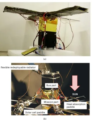
The experimental evaluation of the proposed micro-satellite with functional thermal control system was conducted in the space environment. Figure 8 shows a thermal test model (TTM) which simulates the thermal properties of the satellite by using a mockup model. Especially the mission part and the functional thermal control devices in TTM have the same specifications as the flight model (FM). Meanwhile the bus part consists of substitutes except the body structure and the camera module. The weight of TTM is about 2.7 kg and the estimated weight of FM becomes 2.9 kg which satisfies the upper limit of 3U standard ~3.9 kg.Figure 9 shows the experimental setup for the space environment testing by using a space chamber. The wall temperature of the space chamber is kept from −170˚C to −190˚C by liquid nitrogen and the pressure of the space chamber is 10−5 Pa or lower. TTM is placed with the bottom up in the space chamber as shown in Figure 8(b) and TTM is fixed with polyester cable to minimize the heat leak due to conduction. A heater was used to provide the thermal input from the sun. The temperature of each part is measured by T type thermo-couples. At the beginning of the space environment testing, each element of the thermal devices and each equipment of the payload were tested and moreover the operation test with the satellite as an integrated system was conducted.
4.2. Experimental Results of Space Environment Testing
DOI: 10.4236/jectc.2018.81001 11 Journal of Electronics Cooling and Thermal Control (a)
[image:11.595.226.527.64.455.2](b)
Figure 8. Images of thermal test model and set up of TTM in space chamber. (a) TTM model; (b) TTM in space chamber.
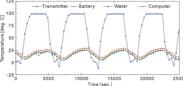
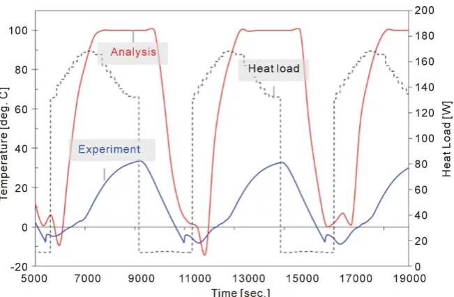
[image:11.595.213.536.507.701.2]DOI: 10.4236/jectc.2018.81001 12 Journal of Electronics Cooling and Thermal Control Figure 10. Temperature history of water in the space environment testing.
the temperature history of water. From the experimental result, periodic tem-perature fluctuations occurred from −9˚C to 37˚C and accordingly only the sol-id-liquid phase change occurred without the gas-liquid phase change. The causes of this problem were considered as follows: 1) the increasing of thermal radia-tion from the paddle surfaces, and 2) the small conductance between the gra-phite sheet and the water chamber. The problem 1) was ascribed to the proper-ties of the surface paint or the gap between the substrate and graphite sheet. The problem 2) was ascribed to the poor contact to water chamber or the deflection of the hinge part. Finally, it was found that the thermal radiation of TTM was 1.7 times as large as the estimation and the thermal conductance between the water chamber and GS was about one fifth of designed value by the thermal analysis. Considering above things, it is required that the values of thermal conductance at the thermal analysis is applied by feedback values from the experiment to im-prove a good agreement between analysis and experiment.
4.3. Experimental Results of Functional Thermal Control System
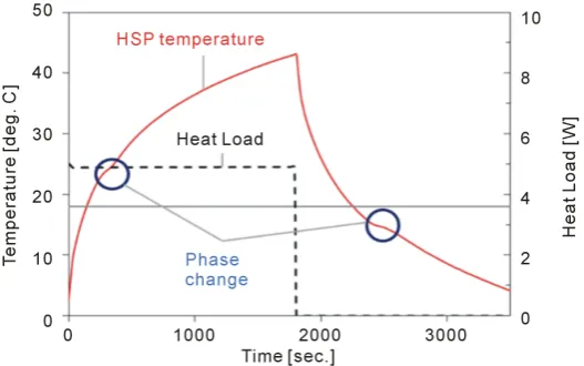
Figure 11 shows the operation test result of HSP which indicates the perfor-mance as predicted by the design. The degradation of HSP or the leakage of PCM by iteration was not observed. Furthermore, the thermal storage perfor-mance was considered. The estimated amount of heat storage was 552 J which corresponds to 97% of the theoretical value [19].DOI: 10.4236/jectc.2018.81001 13 Journal of Electronics Cooling and Thermal Control Figure 11. Operation test result of heat storage panel in the vacuum test.
Figure 12. Operation test result of micro loop heat pipe in the vacuum test.
about 10 cm. Therefore, the high heat flux was needed at starting point because the vapor has to push back the liquid phase in the vapor line to CC against grav-ity. The heat load was changed from 2 W to 5 W. The results showed the oper-ating temperature of 76˚C at the heat load of 3 W and the maximum heat load of 5 W.
Figure 13 shows the operation performance of the flexible re-deployable ra-diator in the space environment testing. After two periods which became a me-tastable state, the flexible re-deployable radiator could work as the same temper-ature change in each cycle.
4.4. Experimental Results of Water Phase Change
DOI: 10.4236/jectc.2018.81001 14 Journal of Electronics Cooling and Thermal Control Figure 13. Temperature history of flexible re-deployable radiator in the space environ-ment testing.
(a) (b)
(c) (d)
[image:14.595.208.538.323.680.2]DOI: 10.4236/jectc.2018.81001 15 Journal of Electronics Cooling and Thermal Control and Figure 14(b) show the picture of the solid-liquid solidification and Figure 14(d) shows a camera angle. The entire observation area became white by freez-ing at the phase change process of solidification. The detail of solidification was as follows; first, the circumference of the thermal conductivity material started to freeze at 0˚C or below, secondly, the rapidly phase change occurred around the first freezing area during the temperature increasing after supercooling, and fi-nally, the vicinity of view port was frozen. Figure 14(c) shows the picture of the gas-liquid phase change. The boiling was observed during the gas-liquid phase change above 100˚C, although the temperature was not constant. The behavior of boiling became most active around 110˚C.
5. Conclusions
A functional and high-performance thermal control system with no power supply for a high-power micro-satellite: 100 W, 3 U has been proposed. To de-sign this system, a demonstration satellite which can absorb the solar heat of 100 W was proposed and the experiment of three phase changes of water was con-ducted as the testbed of 100 W thermal control system. The basic design of the micro-satellite was divided into the payload design and the bus part design. The feasibility of the mission was proved by thermal mathematical model as follows: 1) the solar input to paddles could reach 180 W and the paddles can absorb the thermal energy up to 97 W; 2) the phase change of water led to a temperature change from −10˚C to 100˚C and reveals the possibility of the phase change test; and 3) the temperature of bus equipment was also within the allowable temper-ature range (0˚C - 40˚C). Furthermore, the thermal test model was built and the test results confirmed the operation of the functional thermal control system with HSP, m-LHP and FRDR in the space environment testing, although the temperature fluctuation at the payload was not enough to satisfy the require-ment. In order to develop the functional thermal control systems applied for high-power micro/nano-satellites, the future works are expected as follows: 1) a reduction of thermal resistance between the graphite sheet and water chamber, 2) a suppression of thermal radiation on the paddle, and 3) the optimization of FRDR and m-LHP toward the satellite.
References
[1] Butler, D. (2014) Many Eyes on Earth: Swarms of Small Satellites Set to Deliver Close to Real-Time Imagery of Swathes of the Planet. Nature, 505, 143-145.
https://doi.org/10.1038/505143a
[2] Hand, E. (2015) Startup Liftoff. Science, 348, 172-177.
https://doi.org/10.1126/science.348.6231.172
[3] Klesh, A. and Krajewski, J. (2015) MarCO: CubeSats to Mars in 2016. Proceedings of 29th Annual AIAA/USU Conference on Small Satellites, Logan, 8-13 August 2015, Paper No. SSC15-III-3.
[4] Rice, R. (2014) Design of High Power Cube Satellite Power System, Proceedings of
DOI: 10.4236/jectc.2018.81001 16 Journal of Electronics Cooling and Thermal Control
[5] Yamada, K., Nagano, H., Kobayashi, Y. and Totani, T. (2014) Heat Storage Panel Using a Phase-Change Material Encapsulated in a High-thermal Conductivity CFRP for Micro Satellites. Proceedings of 44th International Conference on Envi-ronmental Systems, Tucson, 13-17 July 2014, Paper No. ICES2014-119.
[6] Gottero, M., Perotto, V., Martino, R., Leyda, B. and Ozmat, B. (2014) Phase-Change Thermal Capacitors for ExoMars 2016 Mission. Proceedings of 44th International Conference on Environmental Systems, Tucson, 13-17 July 2014, Paper No. ICES2014-147.
[7] Birur, G.C. and O’Donnell, T.P. (2001) Advanced Thermal Control Technologies for Space Science Missions at Jet Propulsion Laboratory. AIP Conference Proceed-ings, 552, 263-270. https://doi.org/10.1063/1.1357933
[8] Nabity, J.A. (2014) Modeling a Freezable Water-Based Heat Exchanger for Use in Spacecraft Thermal Control. Journal of Thermophysics and Heat Transfer, 28, 708-716. https://doi.org/10.2514/1.T4351
[9] Ku, J. (1999) Operating Characteristics of Loop Heat Pipes.29th International Con-ference on Environmental System, Denver, 12-15 July 1999, Paper No. 1999-01-2007.
https://doi.org/10.4271/1999-01-2007
[10] Maydanik, Y., Vershinin, S., Chernysheva, M. and Yushakova, S. (2011) Investiga-tion of a Compact Copper-Water Loop Heap Pipe with a Flat Evaporator. Applied Thermal Engineering, 31, 3533-3541.
https://doi.org/10.1016/j.applthermaleng.2011.07.008
[11] Fukushima, K. and Nagano, H. (2017) New Evaporator Structure for Micro Loop Heat Pipes. International Journal of Heat and Mass Transfer, 106, 1327-1334.
https://doi.org/10.1016/j.ijheatmasstransfer.2016.10.116
[12] Ogushi, T., Haga, S., Ishikawa, H., Yao, A., Miyasaka, A. and Noda, H. (2001) Ma-thematical Modeling for Predicting Steady State and Transient Characteristics of Reservoir Embedded Looped Heat Pipe (RELHP). SAE Technical Paper, Paper No. 2001-01-2239.
[13] Nagano, H., Nagasaka, Y. and Ohnishi, A. (2006) Simple Deployable Radiator with Autonomous Thermal Control Function. Journal of Thermophysics and Heat Transfer, 20, 856-864. https://doi.org/10.2514/1.17988
[14] Nagano, H., Ohnishi, A. and Nagasaka, Y. (2011) Development of a Lightweight Deployable/Stowable Radiator for Interplanetary Exploration. Applied Thermal En-gineering, 31, 3322-3331. https://doi.org/10.1016/j.applthermaleng.2011.06.012
[15] Ono, S., Nagano, H., Nishikawa, Y., Tachikawa, S. and Ogawa, H. (2013) Study on an Advanced Deployable Radiator with High-Thermal-Conductive Graphite Sheets for Small Satellites. Proceedings of 43rd International Conference on Environmen-tal Systems, Vail, CO, 14-18 July 2013, Paper No. ICES-2013-3437.
https://doi.org/10.2514/6.2013-3437
[16] Jani, J.M., Leary, M., Subic, A. and Gibson, M.A. (2014) A Review of Shape Memory Alloy Research, Applications and Opportunities. Materials and Design, 56, 1078-1113. https://doi.org/10.1016/j.matdes.2013.11.084
[17] Totani, T., Ogawa, H., Kuramoto, Y., Miyashita, N., Wakita, M. and Nagata, H. (2016) Verification of Rapid Thermal Design Approach Using Design and Flight Data of Hodoyoshi-1 Microsatellite. Proceedings of 46th International Conference on Environmental Systems, Vienna, Austria, 10-14 July 2016, Paper No. ICES2016-116.
DOI: 10.4236/jectc.2018.81001 17 Journal of Electronics Cooling and Thermal Control
[19] Lee, S.A., Leimkuehler, T.O., Stephan, R. and Le, H.V. (2010) Thermal Vacuum Test of Ice as a Phase Change Material Integrated with a Radiator. Proceedings of
40th International Conference on Environmental Systems, Barcelona, Spain, 11-15 July 2010, Paper No. ICES2010-6113. https://doi.org/10.2514/6.2010-6113
Nomenclature
Esun = Sunlight intensity
T = Temperature
Q = Amount of heat
Greek
α = Solar absorptance
ε = Emittance
θi = Incident angle of solar light σ = Stefan-Boltzmann constant
Subscripts
abs = Absorption
space = Space environment
surf = Surface
Abbreviations
CFRP = Carbon Fiber Reinforced Polymer
FM = Flight Model
FRDR = Flexible Re-Deployable Radiator GS = Graphite Sheet
HSP = Heat Storage Panel
LHP = Loop Heat Pipe
PCM = Phase Change Material
SMA = Shape Memory Alloy