PLC Modeling and Checking Based on Formal
Method*
Yueshan Zheng1,2, Guiming Luo1,2, Junbo Sun1,2, Junjie Zhang1,2, Zhenfeng Wang1,2
1Tsinghua National Laboratory for Information Science and Technology, Tsinghua University, Beijing, China; 2School of Software, Tsinghua University, Beijing, China.
Email: [email protected], [email protected]
Received September 5th, 2010; revised September 16th, 2010; accepted September 24th, 2010.
ABSTRACT
High reliability is the key to performance of electrical control equipment. PLC combines computer technology, auto-matic control technology and communication technology and becomes widely used for automation of industrial proc-esses. Some requirements of complex PLC systems cannot be satisfied by the traditional verification methods. In this paper, an efficient method for the PLC systems modeling and verification is proposed. To ensure the high-speed prop-erty of PLC, we proposed a technique of “Time interval model” and “notice-waiting”. It could reduce the state space and make it possible to verify some complex PLC systems. Also, the conversion from the built PLC model to the Pro-mela language is obtained and a tool PLC-Checker for modeling and checking PLC systems are designed. Using PLC-Checker to check a classical PLC example, a countexample is found. Although the probability of this logic er-ror occurs very small, it could result in system crash fatally.
Keywords: Model Checking, PLC Modeling, PLC-Checker, Formal Method
1. Introduction
PLC is an automatic control device that can receive in-formation from sensors, computing device or other PLC logic input signal, and output the logic signal processed. The control algorithm can be written using standard lan-guage, such as Ladder Diagram (LD), Structured Text (ST) or Instruction List (IL) [1].
The technique of PLC using programmable language to control large scale integrated circuit has been widely used in industry [2]. Because of safety critical software can cause serious damage to life or property, verification of safety critical software has become an indispensable step required to assure software quality. The present verifying method for the PLC is still stuck by simulation and test-ing. However, they cannot cover all possible cases, espe-cial whether the design model of PLC to meet the demand. Therefore, the model checking technology is introduced into the field of PLC. To give theoretical analysis of PLC design becomes important.
The primary step of PLC model checking is to the es-tablishment of PLC model, such as establish a model from Function Charts [3]. The PLC model focuses on the
establishment of the time attributes [4]. It can be modeled by the method of timed automata [5] or time period mod-eling method [6]. Thus state space of the model will be decreased compared to timed automata. Either way one choose, eventually an abstract model can be given [7]. How to build a good PLC abstract model is the most im-portant issue to the checking. As the manually modeling is easy to introduce many errors, so the establishment of an integrated modeling and testing tool is very important, and this is one of the issues of concern to this paper.
PLC control program runs in real-time operating sys-tem (multi-task or single-task); this paper is mainly based on multi-task scheduling PLC system. Section 2 of the article has an introduction to the modeling method of PLC system. Section 3 gives the analysis and improve-ment of this model as we need to reduce the probability of pseudo-errors. Section IV designs a model checking tool PLC-Checker to check the established model, including introduce the way of converting PLC program into SPIN's input language Promela code. Finally, a classical PLC example is applied to check and a critical couter-example is found by the PLC-Checker.
2. PLC Modeling
*This work is funded by NSFC 60973049, 60635020, and TNList
prop-erty description, and verification. The most important is how to build the system model.
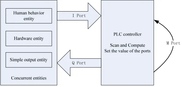
In the system, PLC controller is not isolated, but has interaction with its working environment, driver and hu-man [8]. Therefore, these factors should also be modeling. The environment, human, and the PLC controller is inde-pendent and concurrent with each other in logic. Also, the model checker SPIN’s input language Promela is focused on describing the concurrent, so starting from this idea, we build these factors into several concurrent processes to fit the checking from SPIN, it will also accurately de-scribe the system. To dede-scribe conveniently, they will be called concurrent entities. PLC controller interacts with the concurrent entities through the symbols in image table. The symbols of PLC system include I (input port), Q (output port), and M (intermediate relay). Figure 1 is a
diagram of PLC system model.
Time interval modeling strategy: using the flag which specific the bit state of concurrent entities to represent the concurrent entities in the state, without regard to the system clock. This may neglect the time difference of states, thus simplifying the PLC model. The modeling strategy does not add the system clock properties, not fully corresponds with the original PLC model. That is mainly due to join the system clock will cause PLC system model become too large, there is no for model checking tool to deal with such a large model. The starting point for modeling the state like this is not to consider the number of PLC scans when a migration is experienced. No matter how many scans it experienced, they will all include in this model. In other words, the real model will be a subset of the built model (Time interval model).
The real PLC environment is complex, and includes a variety of hardware and human behavior. The following we will give an analysis of different kinds of PLC envi-ronment concurrent entities.
1) Hardware entity
Hardware entity of the PLC system is mainly some equipment that PLC controls. The state of these equip-ments can be the input of PLC controller. Therefore, the hardware entity binding with its associated I and Q, while the hardware has its own workflow, this workflow is de-cided by the hardware requirements. This work flow can be abstracted into automata. This automata is used to de-scribe the working status of the hardware.
Definition 2.1. A Hardware entity is a tuple Env = <Ienv,
Qenv, A>, where Ienv is the I port binding with the hardware
entity, Qenv is the Q port binding with the entity. A is the
automata that describes the work flow of the entity, A is a tuple A = <s0, S, T>, where s0 is the initial state of A, S is
the set of states while T is the set of the transfers.
The states of hardware entities is a subset of I symbols, and the Is sign each state are all mapped to {True, False}, the I symbol do not appear in the state can be either True or False (that is: act arbitrarily). The transfer of the hard-ware entities directly expressed with the subset of Q symbols, said that all Q symbols in the subset be true at the same time will drive migration between states. The state transition diagram of hardware entities also need to specify an initial state, the transitions graph starts from this state.
The hardware entities’ states of transition diagram are based on the division of symbol I, and time properties are not taken into account. Hardware entities state transition diagram is actually an abstract of hardware entity ignored time, the abstract simulation required reference of the hardware.
2) Simple output entity
[image:2.595.146.452.554.701.2]Simple output entity only binding with the Q port without using I port, that means the simple output entities does not have a state transition diagram. Simple output entity is the equipment that shows the work state of PLC, like a signal light. The usage of the simple output entity is to bind with the Q port such that the PLC can make its logical design.
3) Human behavior entity
Definition 2.2. A Human behavior entity is a tuple Env
= < Ienv, A>, where Ienv is the I port binding with the hardware entity, Qenv is the Q port binding with the en-tity. A is the automata that describes the work flow of the entity, A is a tuple A = <s0, S, T>, where s0 is the initial state of A, S is the set of states while T is the set of the transfers.
Human behavior entity is similar with Hardware entity; they have the same state definition. It is difficult to simu-late the behavior of people, especially the design of a PLC to a number of individuals involved. In response to these difficulties, human behavior modeling should take an iterative process: First, a simple behavior model is built use the model validation; then, if not find a counter example, a more complex model is built, and validate, until find a counter-example or hard to be more complex; Finally, if not previously find a meaningful counter-ex-ample, then generate a completely random person behav-ior model (that is: human behavbehav-ior is a complete graph with all transfers be true) to verification. However, com-pletely random behavior’s verification will cause state space increases dramatically, so how to choose a suitable model of human behavior is the difficulty in modeling. If the person's input is relatively simple, we can use com-pletely random behavior modeling, otherwise, you need to seriously consider the establishment of a rational model of human behavior.
We build model to PLC environment and the human behaviors above, and then we will model the PLC con-troller. PLC controller will be in a loop when it is turned on.
PLC read all the input from I ports.
PLC compute all the logic units.
PLC set all the Q ports.
PLC process on the basic unit called Network. All the networks will operate in order according to the number set when design.
Basic logic operation network of PLC controller in-cludes: S Trigger, R Trigger, SR flip-flop, EQ trigger, RS flip-flop, POS rising edge detector, NEG falling edge detector and so on. To the basic logic operation network modeling, we use direct mapping strategy, namely: PLC controller model of network behavior and the logical be-havior of the network is completely equivalent. Where S trigger, R trigger, SR flip-flop, EQ trigger, RS flip-flop can directly use Boolean expressions to mapped to their behavior.
3. PLC Model’s Analysis and Improvement
The previous section describes the modeling of a PLC system, according to this strategy; we can abstract a PLC
system as a formal model for model checking. Therefore, this model will have a direct decision of the credibility of the model checking results. If the model does not fully cover the original system (we call smaller than the origi-nal system), there may cause some errors are not detected; model can be completely covered if the real system, but it contains many states that the original system does not exist (we call it larger than the original system), this may introduce some errors that real system do not exist. Here called it pseudo-error. So there are two requirements for modeling strategy.
First, in order to find all the errors in the system, we shall build a model large enough to cover all the states in the original system; second, require the model be close to the real system as much as possible. This will not only reduce the state space, but also improve efficiency. Base on the requirements, we will give an analysis about the Time interval model.
Proposition 1 If time interval model conforms the
property, real PLC system model also conforms.
The correctness of Proposition 1 can be concluded from the relationship between the two models. That means all the situations that real model will happen are included by the time interval model, time interval model is larger than the real model. If you couldn’t find a counter-example by using a time interval model, you can prove the correctness of the real PLC model; the other hand, if we find a counter-example, we cannot determine whether there are errors in the real PLC system. That is to say the converse of proposition 1 is wrong. Then manual intervention is required to analyze the anti-cases to de-termine whether it is a pseudo-error.
Time interval modeling strategy can get an abstract PLC model, many research based on NuSMV also use the strategy similar to time interval model to model PLC sys-tem. However, the “time interval model” has large devia-tion with the real model, it needs to be improved. The deviation is: “time interval model” does not reflect the high-speed scanning characteristics of PLC and low-speed characteristics of concurrent entities. That is, all the changes in the environment should be scanned by the high-speed PLC, but the time interval model ignores the high-speed characteristics of PLC, which makes changes in the external environment may not be scanned.
Figure 2. Notice-waiting mechanism of concurrent entities.
concurrent entities to remove the block and go on work-ing. Then the transfer finished. The process that concur-rent entities work to complete the migration by no-tice-waiting mechanism is shown in Figure 2:
t0: Transfer start, block and notice the PLC
control-ler.
t1-tm: PLC completely scanned m times (m is one at
least).
tm+1: The concurrent entities get the notice from the
PLC, transfer finish.
This mechanism ensures every state change of current entities can be scanned at least once by PLC con-troller.
Proposition 2 After add the notice-waiting mechanism,
the model become a subset of the time interval model. At the same time, the model can also include the entire situa-tion in real model. That is to say, if a model which adds the notice-waiting mechanism conforms the property, real PLC system model also conforms.
It is similar to prove proposition 2 with proposition 1. By proposition 2 we can see, after add the notice-waiting mechanism the model still has a good nature. As previ-ously mentioned, an abstract system model has two re-quirements: first, to fully contain the real system, fol-lowed by the model as close to real systems. The first proposition is proved that the time interval model in-cludes the real systems, as long as the use of model checking tools to prove that this abstract model satisfies a certain property, then the true nature of the system will also satisfy this. But this model and the real model is not entirely equal, it should be far greater than the real model. Compare to time interval model, this model further duced the distance between the real systems, greatly re-duce the chance that finding out pseudo-errors.
Model checking tool will give out a counter-example violate the property of the system; it is easy to manually determine the counter-examples in the real system is true or not. If the errors in the original system really exist, then we find a counter-example. Otherwise, this error is
because the abstract model is larger than the real system, it is a pseudo-error. Therefore, although this time interval model and the original system are not fully equivalent, but by this model, we can judge a system meets a certain property, if not we can find a specific counter-example (still needs more examine to determine whether it is a pseudo-error).
Model is not equivalent with the original system, mainly because there are many factors difficult to model in real systems, some of which may give rise to error. If all the factors are modeled, that will lead to the estab-lishment of a huge model that cannot check, or simply cannot be achieved. Time interval model abstract the key factors from the real system and model them, greatly reducing the state space, and reduce the time complexity. Meanwhile, add by the notice-waiting mechanism, the model become much closer to real systems, not only re-duces the time complexity, while it reduced the pseu-do-errors mentioned before.
4. PLC Model Checking
PLC is widely used in many applications, and has many devices; this is a large area of research. Any PLC work in the environment that includes different equipment and people, so PLC system is concurrent. At the same time, a PLC system difficult to find if there are some errors, mostly because of the logical design errors, but not the calculation error. So we focus on the detection of PLC program logic process, and this logic can be completely described by bit logic. Therefore, in order to simplify the PLC program model, focused on model checking, we make the following settings:
PLC is a logic control program, all the control va-riables only has two states 0 and 1;
PLC program is run in concurrent environment. In this case, PLC programming is more likely to have some errors not easy to find.
realized NuSMV) on the above established model for checking. We made a series of transformation rules, build the above model into SPIN's input language Pro-mela, the system property also need to be translated into Promela, SPIN will put them together and then perform detection.
PROMELA language is a C class language, they are similar in semantic. So we will only give some examples to show the basic concept of the translation. To see the details of PROMELA language, please visit www.spin-root.com. We will introduce the three part of a PRO-MELA file as the input of SPIN.
1) Code of PLC controller
PLC controller is composed of multiple networks. Code of PLC controller is also generated from the net-work. Of course, before that, you should declare the vari-ables you need. Each network has its input ports and out-put ports, each port can be indicate by a Boolean expres-sion. We assign the output port’s value through the logic computing of all the input port. This is the translation approach of PLC network.
Here is an example of converting SR network: if
:: Exp(R) == 1 -> Q = 0; ::else ->
if ::Exp(S) == 1 -> Q = 1; ::else -> skip; fi; fi;
/* Exp(S) is the Boolean expression of S port Exp(R) is the Boolean expression of R port Q is the output port */
2) Code of concurrent entities
We consider each concurrent entity a unique process, no matter it is human behavior or equipment. These processes share variables with PLC controller process. This must be done to ensure the concurrency of the system.
In the 2nd part of this paper, we discuss that all the concurrent entities are modeled as an automata. The meaning of automata is to transfer from a state to another. We use the I port to form the state of the entities. Use goto statement as the transfer (just like in Assembly lan-guage). A simple example is shown like below:
StateA: atomic {
if
:: Q1 -> {IB, goto StateB} :: Q2 -> {IC, goto StateC} fi;}
/* StateA is the label of State A Q1, Q2 is the condition of transfer
IB is to set the state value to the value of state B goto StateB means jump to stateB */
3) Code of property
Property is the rule that the PLC system must obey. We use LTL (Linear Time Logic) formula as the input format. We should write the counter-property because of the mechanism of SPIN. SPIN will find a situation that our property happens, that should be a counter-example.
We couldn’t directly write the LTL formula, but by us-ing macros. Firstly we should define all the propositions in the LTL in a macro (like # define p i5 == 0), then we use propositions defined to form a LTL formula. SPIN can automatically convert the LTL formula to PRO-MELA code by using “SPIN–f” instruction (see more details in manual of SPIN).
4) Notice-waiting mechanism
In the modeling discussion, we propose to add no-tice-waiting mechanism. This mechanism also needs re-flected in the code. Specific implementation is to sign a bit variable for each non-PLC process (all the process except PLC controller) as a signal. When the automata transfer to a state label, the signal variable is set to 0, and the next assignment requires this variable to be 1 to con-tinue. As the result of PROMELA grammatical features, the process will hang onwards. In the PLC process no such restrictions, on the contrary, PLC process can set these variables to 1, thus ensuring every move must go through at least one PLC scan to complete. That is the so called notice-waiting mechanism.
Follow the four steps above; we get a complete code of a SPIN input file of our system. Then we can use SPIN to check the model. For the steps of operating SPIN model checker, see the manual of SPIN (visit www.spin-root.com). SPIN will give the result whether a counter- example is found, and we can analyze using the theory mentioned above with the trail files that spin gives. Using this detection mechanism, we developed a tool for model checking PLC-checker. It helps to build visual models and the implementation of checking, and can give a simple analysis to the result. Of course, the coun-ter-example it find should be checked manually to make sure whether it is a true counter-example. However, with the help of trail file, this is not a very difficult task. We also successfully implemented some checking using PLC-checker (shown in the next section). In a classic textbook example, a counter-example was found. Al-though the probability of occurrence of counter-example is very low, but it does happen and can have serious con-sequences. This tool is also proves the correctness and validity of the theory in this article.
5. Running PLC-Checker
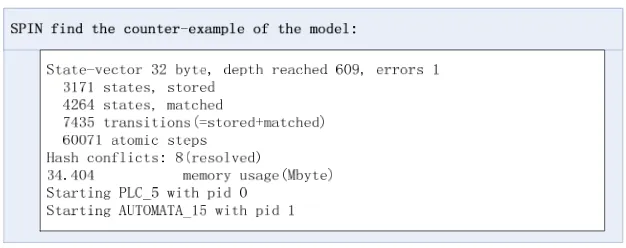
Figure 3.Result of model checking.
By input the ladder gram and the concurrent entities into the tool, also the definition of the property, we exe-cute the checking. Figure 3 shows the result.
As we can see, there is one error in the result. It is proved to be a true counter-example by checking the trail file manually. That is to say our mechanism is effective in checking such kind of PLC programs.
6. Conclusions
We study the theory of modeling and checking on PLC system in formal method in this paper. The requirement of PLC modeling is analyzed, and the models of concur-rent entities are built up through time interval strategy. Then we prove the time interval model a super set of the PLC system, and decrease the model by adding no-tice-waiting mechanism. It also ensures all the changes in the system can be scanned by the PLC controller. We find the error of the system by checking out the coun-ter-example of the system. Finally, the way of using SPIN to check the model is given. Also the corresponding model checking tool PLC-Checker is introduced. In this stage, the mechanism still has many imperfections, such as the handling of the timer. But it has great and unique advantages in solving the problem of state exploration. We are still on active exploration of such issues.
REFERENCES
[1] Pavlovic, R. Pinger and M. Kollmann, “Automated For-mal Verification of PLC Programs Written in IL,” Con-ference on Automated Deduction (CADE), Bremen, July
2007, pp. 152-163.
[2] M. B. Younis and G. Frey, “Formalization of Existing PLC Programs: A Survey,” Proceedings of CESA 2003,
Lille, 2003.
[3] N. Bauer, S. Engell, S. Lohmann, M. Remelhe and O. Stursberg, “Verification of PLC Program Given as Se-quential Function Charts,” Lecture Notes in Computer Science, Vol. 3147, 2004, pp. 517-540.
[4] S. R. Koo, P. H. Seong and S. D. Chaa, “Software Design Specification and Analysis Technique for the Safety Critical Software based on Programmable Logic Control-ler (PLC),” Proceedings of the Eighth IEEE International Symposium on High Assurance Systems Engineering
(HASE’04), Florida, March 2004, pp. 283-284.
[5] A. Mader and H. Wupper, “Timed Automaton Models for Simple Programmable Logic Controllers,” Proceedings of the 11thEuromicro Conference on Real-Time Systems
1999, York, June 1999, pp.106-113.
[6] E. Brinksma1, A. Mader and A. Fehnker, “Verification and Optimization of a PLC Control Schedule,” Interna-tional Journal on Software Tools for Technology Transfer
(STTT), Vol. 4, No. 1, October 2002, pp. 21-33.
[7] S. Lamp′eri`ere and J. J. Lesage, “Formal Verification of the Sequential Part of PLC Programs,” 5th Workshop on Discrete Event Systems (WODES 2000), Ghent, August 2000, pp. 247-254.