ISSN Online: 2331-4249 ISSN Print: 2331-4222
DOI: 10.4236/wjet.2019.73037 Aug. 23, 2019 520 World Journal of Engineering and Technology
Study of External Characteristics of Hydraulic
Electromagnetic Regenerative Shock Absorber
Muhammad Yousaf Iqbal, Zhifei Wu
*, Guangzhao Xu, Syed Arslan Bukhari
School of Mechanical Engineering, Taiyuan University of Technology, Taiyuan, China
Abstract
According to the composition and the principle of the liquid-electric ener-gy-sensing damper, the corresponding hydraulic regenerative model is de-signed. In this paper, an advanced type of shock absorber combined with the mechanical and electromagnetic hydraulic structure has been proposed that recycles the energy dissipated by shock absorber in the driving process. In addition, the damping characteristics of the conventional mechanical vehicle and the advanced hydraulic regenerative mechanical vehicle have been ana-lyzed by using AMESim simulation. The regenerative suspension is reformed from the traditional hydraulic and pneumatic suspension. The suspension absorbs kinetic energy converts it into hydraulic potential and pneumatic power to be stored in the accumulator. The kinetic energy is then converted into electricity instead of heat by using the hydraulic suspension and Pow-er-Generating Shock Absorber (PGSA). The AMESim simulation results have efficiently verified the displacement characteristics curves and flow rate of hydraulic fluid in the body. Finally the conversion of energy produced by ad-vanced hydraulic regenerative mechanical vehicle transferred into electrical energy. The designed hydraulic shock absorber allows a significant fuel saving of 1.5% to 4% depending on the vehicle and driving conditions.
Keywords
AMESim, Producing Electricity, Ride Comfort, Hydraulic Shock, Accumulator, Characteristics Curves
1. Introduction
Suspension plays a vital role in vehicles, especially to maintain the ride comfort and road handling performances, by using oil shock absorbers to dissipate the vibration energy in them. Energy recovery from shock absorbers is a kind of How to cite this paper: Iqbal, M.Y., Wu,
Z.F., Xu, G.Z. and Bukhari, S.A. (2019) Study of External Characteristics of Hy-draulic Electromagnetic Regenerative Shock Absorber. World Journal of Engineering and Technology, 7, 520-535.
https://doi.org/10.4236/wjet.2019.73037
Received: July 23, 2019 Accepted: August 20, 2019 Published: August 23, 2019
Copyright © 2019 by author(s) and Scientific Research Publishing Inc. This work is licensed under the Creative Commons Attribution International License (CC BY 4.0).
DOI: 10.4236/wjet.2019.73037 521 World Journal of Engineering and Technology method recovery energy of vibrations. Researchers have developed energy re-covery since the early 1990s. Early energy rere-covery with active control and rege-nerative control of active vibration damper concept was proposed in 1996 [1] [2], and the idea was relying on linear DC motors. However, linear motors were generally costly, and linear motors efficiency was much lower than rotary. Then Graves [3] developed their energy-regenerative shock absorber by using a ball screw mechanism and rotary DC motor, while the results suggested that some parts still needed to be improved. Nakano [4] found rotating electromagnetic dampers had the advantage of mechanical amplification, and they have developed extra dynamic elements in series to enhance the vehicle dynamics. Two configura-tions of regenerative electromagnetic shock absorber have been designed for re-covering the energy dissipated in shock absorber a linear device and a rotary de-vice [5]. Li designed and analyzed an electromagnetic harvester for potential ap-plications from vehicle suspension based on rack and pinion [6]. Zhang de-signed a regenerative shock absorber based on an arm teeth mechanism [7]. But energy-regenerative characteristic and the damping characteristic of their pro-gram still needed to be improved. Liu has stimulated and modeled a energy re-generative suspension based on neural network PID control [8], and Zou stimu-lated a hydraulic energy interconnected suspension based on hydraulic ener-gy-regenerative shock absorber (HESA) comparatively with the passive suspen-sions [9]. This study tries to develop another program with rotary motor-HESA to obtain higher efficiency and better reliability [10].
US Patent Publications [11] [12] [13] [14] reveal various similar liquid-electric energy-feeding suspensions, which utilize the oil circuit system design to convert the reciprocating vibration energy of the piston into the hydraulic energy of the damping oil, and the hydraulic motor in the driving system rotates. The damper converts mechanical energy into heat by friction and then dissipates it to reduce vehicle vibration. If this part of the power can be recovered, it is possible to re-duce fuel consumption and achieve energy saving. The damping force created by shock absorbers in traditional suspension is mainly based on orifice compensa-tion and hydraulic actuator [15], which transfers the vibration energy into the damper oil heat, then dissipating into surroundings through the tubes. When vehicles are driving on the road, many factors affect on the vehicle [16] like vi-bration between spring-mass and unspring mass. These vivi-brations are dissipated into heat waste through friction during the damping process. The Damper con-verts mechanical energy into heat energy through dissipation and reduces the vibratory motion of the vehicle. If this part of the power can be recycled, then it would reduce fuel consumption and achieve the purpose of energy-saving.
sys-DOI: 10.4236/wjet.2019.73037 522 World Journal of Engineering and Technology tem pressure changes with the quantity of energy stored, and the energy density is significantly lower than other energy domains. Shock is defined as “a transient condition whereas the kinetic energy is transferred to a system in a period which is short, relative to the natural period of oscillation of the system”. Usually, shock contains a single impulse of the energy of the large intensity and short duration, which replicates in a dramatic change in velocity of the system undergoing shock. The principle involved in both vibration and shock isolation is similar. The dam-per is an essential component in the automotive suspension system, and the hy-draulic oil flows back and forth during the work. The primary function of vehicle suspension is to reduce the vibrational acceleration, deceleration disturbance from road roughness and chassis for better ride comfort and to sustain reasonable tire ground contact force for better vehicle handling. The suspension system is consists of the viscous and spring shock absorber. The regenerative braking systems have become increasingly popular because of recovering energy that would be lost through braking. However, another energy recovery mechanism that is still in the research stages is regenerative suspension systems. This technology can conti-nuously recover a vehicle's vibration less energy dissipation that occurs due to road irregularities, vehicle acceleration, braking, and use the energy to reduce fuel con-sumption. The research group of Wuhan [21] has carried out a lot of research on the liquid-electric energy-feeding suspension, and proposed several implementa-tion schemes of liquid-electric energy-feeding suspensions, from establishing dy-namic models and simulation analysis. In addition, Fang [22] also studied the in-fluence of road excitation frequency, external load and damping coefficient on energy efficiency. Lin Xu [23] have designed a hydraulic transmission electromag-netic energy regenerative active suspension system but in that system have used double accumulators, one was low and other higher precharge pressure accumu-lator that is not more efficient due to volume dynamic response. But in our re-search, we are using one accumulator getting more active, and this study analyses the modeling and simulation of shock absorbers, actuators, and dampers. The main work of this paper designs a hybrid energy damper that can make the oil flow in one direction, drive the generate electricity and obtained asymmetric damping ratio.
2. Working Principle
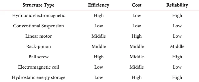
In this paper simulation includes some parameters like a hydraulic cylinder, check valves, hydraulic actuator, accumulator, hydraulic motor, electromotor, pressure sensor, and elastic elements (Table 1).
DOI: 10.4236/wjet.2019.73037 523 World Journal of Engineering and Technology Table 1. Integrate the main structures of the current shock absorber.
Structure Type Efficiency Cost Reliability Hydraulic electromagnetic High Low High
Conventional Suspension Low Low Low Linear motor Middle High Low Rack-pinion Middle Middle Middle
Ball screw High Middle High Electromagnetic coil Low Middle Low Hydrostatic energy storage Low High High
The working principle when the absorber is in the compression stroke, the pis-ton pushes the liquid into the storage generation chamber via check valve 2 be-cause check valve 1 is closed at this time. The hydraulic fluctuation rectified by energy accumulator, and this accumulator pressure increase and volume would be decreased. When the shock absorber subjected to external force from a road pro-file, then this force enhances the hydraulic pressure inside the shock absorber and compressed the gas inside the accumulator. This hydraulic fluid moves towards the hydraulic motor that is connected with the generator and generate the electric-ity. The reaction produced in the working process of the generator makes the hy-draulic motor to produce a damping force against the liquid. This force is trans-mitted to the piston by the liquid to gain the purpose of vibration reduction. For weakening the fluctuation, oil flows through the accumulator. Finally, the conti-nuously steady oil flow drives the hydraulic motor to generate electricity. The liq-uid flows through the hydraulic motor and the check valve 3 and goes back into the chamber below the piston. At the same time, the returning hydraulic pressure affects the check valve 1, while in the compression stroke of the piston, the inside is in high pressure and the returning liquid is in a low pressure, the check valve 1 is closed. The system works a similar way while the absorber is in extension stroke. So, whether the shock absorber is in compression stroke or in extension stroke, the liq-uid flow passing through the hydraulic motor will not change directions (Figure 1).
The lower and upper chambers are connected by the complete rectifier in the double-acting cylinder so its compression stroke and extension stroke could be controlled and recover energy. The primary influence of the hydraulic accumu-lator is to absorb the sudden shocks and minimize pressure fluctuation in our model. In hydraulic electromagnetic regenerative shock absorber, most of the components are from the libraries in AMESim like Mechanical, hydraulic, hy-draulic Components Design, Signal control, and Vehicle dynamics. We are using some interior parameters in our model, as mention in below Table 2.
3. AMESim Simulation Model of Hydraulic Electromagnetic
Energy Regenerative Shock Absorber
DOI: 10.4236/wjet.2019.73037 524 World Journal of Engineering and Technology Figure 1. Configuration of hydraulic transmission electromagnetic energy regenerative shock absorber.
Table 2. Interior parameters.
Sub Model Parameters Unit Value Accumulator Accumulator volume L 1.4
Mass2port Car Body mass kg 400
Mass2port_1 Tyre mass kg 50
Accumulator Pressure at port 1 bar 10 Spring01 Spring rate N/m 150,000 Springdamper01 Spring rate N/m 100,000
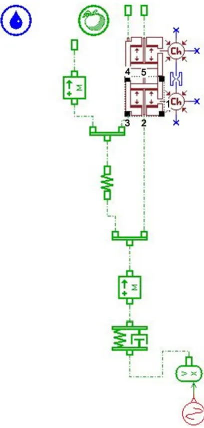
signal control library. No matter the shock absorber is in the extension stroke or compression stroke in the presence of hydraulic rectifier, the hydraulic motor is driven from one side. If hydraulic rectifier is removed, then oil will drive the motor from two sides, and the motor will change its rotational direction twice. In advanced modeling are using a motor of 8 cc/rev displacement and 4000 rev/min while in traditional no use of motor, accumulator and check valve. The configuration of the hydraulic electromagnetic type shock absorber is shown in the following Figure 2. The hydraulic cylinder piston drives the oil to flow to-ward the accumulator under the excitation of the external; then the oil is sent to the hydraulic motor to rotate the motor, which will drive the generator to gener-ate electricity (Figure 3).
[image:5.595.206.541.334.453.2]DOI: 10.4236/wjet.2019.73037 525 World Journal of Engineering and Technology Figure 2. Circuit schematics diagram on AMESim of advanced hydraulic regenerative shock absorber.
[image:6.595.271.475.281.708.2]DOI: 10.4236/wjet.2019.73037 526 World Journal of Engineering and Technology are set according to QC/T 545-1999 (Experimental telescopic shock absorber suspension testing). The real parameters stroke is 100 mm, and the frequency is 1.67 Hz. The cylinder bore of the absorber and the diameter of the piston rod is 50 mm and 20 mm respectively. This submodel is used to provide supplementa-ry ports for BHC11. The hydraulic volume with pressure dynamics has real pa-rameter dead volume 50 cm3. BRP18 is used to represent part of a jack or valve where a pressure acts on a piston or spool and on the body or sleeve where the piston and the shape of the jack or valve are moving. Use this submodel to con-struct hydraulic jacks and spool valves with moving body. It can also be used for parts of brake systems and automatic gearboxes. The external parameters of pis-ton with moving body are flow rate port 1 42.95 L/min, force at port 2896.06 N, displacement at port 2 is 0.029 m, displacement at port 3 is 0.0198 m, and veloc-ity at port 2 is 6.93 m/s.
[image:7.595.160.540.471.706.2]Use MAS002 for linear motion of a mass with two forces applied to it when there is no friction. In this model, the car body mass is 400 Kg, while the mass of the tire is 30 kg. The real parameters are only mass, and external parameters are velocity pf the car body mass is 7.61 m/s, and velocity of tire body mass is 6.93 m/s. The real parameters of mechanical spring and damper spring rate is 150,000 N/m, damping rating is 1000 N/(m/s), spring force with both displacement 0 N and material shear modulus is 8.57e+10 N/m2. The external parameters are force at port 1 is −1897.16 N, Velocity at port 1, 2 are respectively 6.28 m/s, −6.93 m/s displacement at port 1, 2 respectively are −4.714 m, −0.0069 m. The liquid is in-compressible, and because of the hydraulic pipeline with a larger caliber in the hydraulic electromagnetic energy regenerative absorber, the pipe loss that is of viscous damping can be neglected, then the damping force F is only related to the piston area and the hydraulic pressure P acting on the piston [23] (Figure 4).
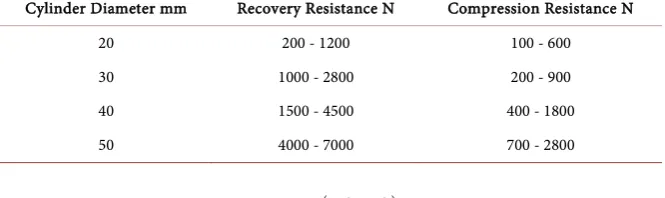
DOI: 10.4236/wjet.2019.73037 527 World Journal of Engineering and Technology Table 3. Recovery resistance and compression resistance force at different cylinder diameter.
Cylinder Diameter mm Recovery Resistance N Compression Resistance N
20 200 - 1200 100 - 600
30 1000 - 2800 200 - 900
40 1500 - 4500 400 - 1800
50 4000 - 7000 700 - 2800
(
2 2)
π 4
D r
F P= −
(1)
The piston speed 0.52 m/s is the damping force of time resistance. When the cylinder bore diameter is 50 mm required we get restoration resistance 4000 - 7000 N and compression resistance 700 - 2800 N, as above Table 3.
The force rate ratio is always greater than 1 and less than 3. This model gets the compression force is F1, 3367.65 N, and expansion force F2, 3676.107 N, and recovery resistance 7043 N.
2 1 3676.10 1.09 3367.65 F Rate F
= = =
(2)
According to the requirements of QC/T 545-1999 national Standard, the test conditions of the piston velocity 0.52 m/s are equivalent. For amplitude is 50 mm and the frequency is 1.67 Hz sinusoidal excitation.
4
π 10 0.52 m s 6
s n
V = × × × − =
(3)
With the following equation, we can calculate the shaft torque,
(
)
π 20
out in
P P disp
torgue= − ×
× (4)
The total liquid flow rate of the hydraulic motor can be calculated by given below equation
(
2 2)
π 4
D d
Q Vp= − (5)
When the slope of signal incentive, the positive portion of the absorber is in the compression stroke and negative is extension stroke. The real parameters of the sine wave frequency are 1.67 Hz, and the phase shift is 270 degree (Figure 5). The components which are used to harvest energy includes hydraulic motor, electromagnetic generator, hydraulic rectifies in the form of a check valve and accumulator (Figure 6).
4. Simulation Results and Discussions
DOI: 10.4236/wjet.2019.73037 528 World Journal of Engineering and Technology Figure 5. Signal incentive.
Figure 6. Energy harvesting block diagram.
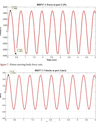
shown in above Figure 3. According to Equation (2), we get the force rate ratio of 1.09, as shown in Figure 7. The test conditions of the piston velocity 0.52 m/s obtained according to Equation (3) and result, as shown in Figure 8.
The maximum shaft speed at 1.67 Hz is 5284.37 rev/min. In the following di-agram, we have compared the shaft speed at different frequency are 0.33 Hz, 0.67 Hz, 1 Hz, 1.33 Hz, and 1.67 Hz (Figure 9).
The maximum shaft speed 5284.37 rev/min gets at 1.67 Hz. Apply the same test parameters in the simulation computing of the energy-regenerative absorber active control model. The result reveals that although the total liquid flow in compression stroke is more significant than that in extension stroke (Figure 10).
Where Vp is the velocity of the piston, and D is the piston diameter. So the pump displacements of the hydraulic motor are 8 cc and 8.2 cc, and the typical speed is 8000 rev/min. The total liquid flow rate of the hydraulic motor can be calculated according to Equation (5).
DOI: 10.4236/wjet.2019.73037 529 World Journal of Engineering and Technology Figure 7. Piston moving body force rate.
Figure 8. Velocity curves of moving piston body.
[image:10.595.207.541.508.705.2]DOI: 10.4236/wjet.2019.73037 530 World Journal of Engineering and Technology greatly influenced by the hydraulic rectifier. Firstly, when pressure drops of the check valve in the hydraulic rectifier dissipate the energy of the system. Second-ly, the hydraulic rectifier’s efficiency decrease with the increase in excitation frequency, due to delay in the time of opening and closing of the check valves, which ultimately leads to a reduction in energy recovery efficiency.
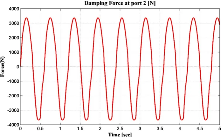
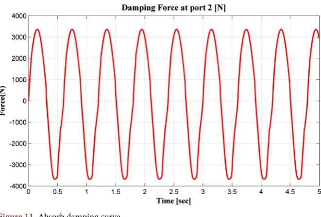
[image:11.595.227.521.231.471.2]By measuring the damping force on piston (Figure 11), we can see that when compression resistance point A is corresponding to that before the control, with the active control over generator load, the hump drag in extension resistance point B is over 3900 N, which is far greater than before the control. The damping force in hydraulic electromagnetic energy regenerative absorber meets the
Figure 10. Liquid flow curve passing through hydraulic motor.
[image:11.595.209.540.497.720.2]DOI: 10.4236/wjet.2019.73037 531 World Journal of Engineering and Technology requirements of the standard QC/T 545-1999.
For conventional and non-accumulating HESA, the damping force gradually changes with the damping movement to reach a maximum value at maximum displacement and then gradually decreases. The maximum damping force only occurs for a short period, in combination with the maximum absorption speed and accumulators play an essential role in energy conservation in HESA.
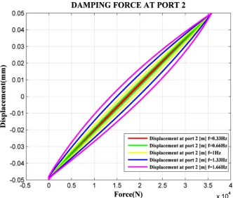
The damping coefficient of the advanced hydraulic regenerative shock absor-ber is not more efficient than the damping coefficient of the traditional conven-tional system at a different frequency, as shown in Figure 12 and Figure 13. The characteristics of ride performance and energy-recovery of the hydraulic-electricity energy regenerative suspension unit were analyzed to compromise between the energy-recovery and dynamic performances. The simulation results show that the accumulator has a more significant influence on the damping force in both the stretching stroke and the restoring stroke, which is the slow rise of the damping force caused by the accumulator energy storage time in the first half of the com-pression stroke. In the second half of the recovery stroke, the impact of the force caused by the end of the accumulator pressure release, and the impact of the force is more obvious when the excitation speed is smaller (Figure 14).
[image:12.595.208.541.425.706.2]However, the vibration takes place is larger when the load excess of the rege-nerative energy suspension with the very of time, and this is caused due to the lag effect which is brought by the filter action of the energy accumulator in the ener-gy-regenerative absorber. The simulation results show that under the step response stimulus, the hydraulic electromagnetic energy-regenerative suspension has a
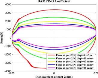
DOI: 10.4236/wjet.2019.73037 532 World Journal of Engineering and Technology Figure 13. Damping coefficient of hydraulic regenerative shock absorber at different fre-quency.
Figure 14. Damping coefficient of hydraulic regenerative shock absorber at different dis-placement of motor.
[image:13.595.207.535.376.636.2]ac-DOI: 10.4236/wjet.2019.73037 533 World Journal of Engineering and Technology cumulators arises in maintaining the maximum damping force for most of the oscillation time and minimizing the pressure fluctuations to ensure the stability of the hydraulic motor rotation.
5. Conclusion
The damping force of the hydraulic electromagnetic energy regenerative absor-ber meets the standard requirements of QC/T 545-1999. This paper proposes a design of an advanced energy regenerative absorber structure and expounds its working principles. An effective simulation modeling way based on AMESim for hydraulic suspension control has been presented in this paper. Simulation with AMESim avoids cumbersome traditional modeling method. The efficiency of sus-pension simulation modeling for vehicle chassis dynamics system is enhanced. The advanced hydraulic electromagnetic shock absorber is more efficient and re-liable than the convention suspension and other suspension systems. The damping characteristic of HESA meets the requirements so that the traditional shock ab-sorbers can be replaced by HESA to some extent. The generator can rotate un-idirectionally and stably, which can extend the life of the generator and can im-prove energy recovery efficiency. The compression resistance force in advanced hydraulic regenerative shock system is always greater than the recovery resis-tance.
Acknowledgements
I would like to pay gratitude heartily to my supervisor Prof. Zhifei Wu for his con-tinuous support for my research, for his patience, enthusiasm, motivation, and immense knowledge. He guided and motivated me throughout the research process and paper writing. Without his kind help and continuous guidance, this research project would not have been completed. Moreover, I would like to thank my parents for their wise counsel and sympathetic ear. You are always there for me. Finally, there are my friends, who were of great support in deliberating over our problems and findings, as well as providing a happy distraction to rest my mind outside of my research. The authors are grateful for the supported by The Shanxi Province Science and Technology Major Project (Grant No. 20181102006).
Conflicts of Interest
The authors declare no conflicts of interest regarding the publication of this pa-per.
References
[1] Suda, Y. and Shiiba, T. (1996) A New Hybrid Suspension System with Active Con-trol and Energy Regeneration. Vehicle System Dynamics, 25, 641-654.
https://doi.org/10.1080/00423119608969226
DOI: 10.4236/wjet.2019.73037 534 World Journal of Engineering and Technology [3] Graves, K.E., Iovenitti, P.G. and Toncich, D. (2000) Electromagnetic Regenerative Damping in Vehicle Suspension Systems. International Journal of Vehicle Design, 24, 182-197.https://doi.org/10.1504/IJVD.2000.005181
[4] Nakano, K. (2004) Combined Type Self-Powered Active Vibration Control of Truck Cabins. Vehicle System Dynamics, 41, 449-473.
https://doi.org/10.1080/00423110512331383858
[5] Gupta, A., Jendrzejczyk, J.A., Mulcahy, T.M. and Hull, J.R. (2006) Design of Elec-tromagnetic Shock Absorbers. International Journal of Mechanics and Materials in Design, 3, 285-291.https://doi.org/10.1007/s10999-007-9031-5
[6] Li, Z., Brindak, Z. and Zuo, L. (2011) Modeling of an Electromagnetic Vibration Energy Harvester with Motion Magnification. In: ASME 2011 International Me-chanical Engineering Congress and Exposition, American Society of Mechanical Engineers,New York, 285-293.https://doi.org/10.1115/IMECE2011-65613
[7] Zhang, R. and Wang, X. (2019) Parameter Study and Optimization of a Half-Vehicle Suspension System Model Integrated with an Arm-Teeth Regenerative Shock Absor-ber Using Taguchi Method. Mechanical Systems and Signal Processing, 126, 65-81.
https://doi.org/10.1016/j.ymssp.2019.02.020
[8] Liu, J., Li, X., Zhang, X. and Chen, X. (2019) Modeling and Simulation of Ener-gy-Regenerative Active Suspension Based on BP Neural Network PID Control. Shock and Vibration, 2019, Article ID: 4609754.https://doi.org/10.1155/2019/4609754
[9] Zou, J., Guo, X., Xu, L., Abdelkareem, M. A., Gong, B., Zhang, J. and Tan, G. (2018) Simulation Research of a Hydraulic Interconnected Suspension Based on a Hydrau-lic Energy Regenerative Shock Absorber. SAE Technical Paper No. 2018-01-0582.
https://doi.org/10.4271/2018-01-0582
[10] Zheng, P., Gao, J., Wang, R., Dong, J. and Diao, J. (2018, September) Review on the Research of Regenerative Shock Absorber. In: 2018 24th International Conference on Automation and Computing, Newcastle upon Tyne, UK, 6-7 September 2018, 1-12.https://doi.org/10.23919/IConAC.2018.8749044
[11] Margolis, D.L., Jolly, M.R., Schroeder, W.R., Heath, M.C. and Ivers, D.E. (1996) Regenerative System Including an Energy Transformer Which Requires No Exter-nal Power Source to Drive Same. US Patent No. 5570286.
[12] Stansbury, J.A. (2012) Regenerative Suspension with Accumulator Systems and Methods. US Patent No. 8261865.
[13] Okamoto, A. (2013) Energy Regeneration Device for either Hybrid Vehicle or Elec-tric Automobile. US Patent No. 8479859.
[14] Carabelli, S., Tonoli, A., Festini, A., Cavalli, F. and Amati, N. (2011) Suspension System for a Wheeled Vehicle and a Wheeled Vehicle Equipped with Such a Sus-pension System. US Patent No. 7942225.
[15] Zhang, Y., Zhang, X., Zhan, M., Guo, K., Zhao, F. and Liu, Z. (2015) Study on a Novel Hydraulic Pumping Regenerative Suspension for Vehicles. Journal of the Franklin Institute, 352, 485-499.https://doi.org/10.1016/j.jfranklin.2014.06.005
[16] Han, W., Guo, Y., Prokop, G. and Roscher, T. (2019) Simulative Research on the Tire Torsional Vibration and Its Vehicle Relevant Influencing Factors. In: Bar-gende, M., Reuss, H.C., Wagner A. and Wiedemann, J., Eds., Internationales Stutt-garter Symposium, Springer Vieweg, Wiesbaden, 1397-1411.
https://doi.org/10.1007/978-3-658-25939-6_111
Tech-DOI: 10.4236/wjet.2019.73037 535 World Journal of Engineering and Technology nical Paper No. 2017-01-1483.https://doi.org/10.4271/2017-01-1483
[18] Zou, J., Guo, X., Xu, L., Tan, G., Zhang, C. and Zhang, J. (2017) Design, Modeling, and Analysis of a Novel Hydraulic Energy-Regenerative Shock Absorber for Vehicle Suspension. Shock and Vibration, 2017, Article ID: 3186584.
https://doi.org/10.1155/2017/3186584
[19] Wendel, G.R., Steiber, J. and Stecklein, G.L. (1994) Regenerative Active Suspension on Rough Terrain Vehicles. SAE Transactions, 20-30.
https://doi.org/10.4271/940984
[20] Senlin, C.S.H.R.L. (2007) New Reclaiming Energy Suspension and Its Working Principle. Chinese Journal of Mechanical Engineering, 43, 177.
[21] Fang, Z., Guo, X., Xu, L. and Zhang, H. (2013) Experimental Study of Damping and Energy Regeneration Characteristics of a Hydraulic Electromagnetic Shock Absor-ber. Advances in Mechanical Engineering, 5, Article ID: 43528.
https://doi.org/10.1155/2013/943528
[22] Fang, Z., Guo, X., Xu, L. and Zhang, H. (2013) An Optimal Algorithm for Energy Recovery of Hydraulic Electromagnetic Energy-Regenerative Shock Absorber. Ap-plied Mathematics & Information Sciences, 7, 2207-2214.
https://doi.org/10.12785/amis/070610