RFID based Library Management System
Prof. Vikas Bhandare1, Ms. Shraddha Khot2, Ms. Shweta Surve3, Ms. Tina Bhurkre4, Ms. Tejaswini Mohite5, Ms. Pranita Patil6
1
Professor in Department of Electrical Engineering, SGI, Atigre.
2, 3, 4, 5, 6
Student in Department of Electrical Engineering, SGI, Atigre.
Abstract: In this paper we have used Radio Frequency Identification (RFID) technology. Radio Frequency Identification (RFID) is the new generation of Auto identification without any physical contact. This paper presents an overview of RFID based Library Management System which allows the fast transaction of books and make it easy to handle the issue and return of the books from the library. RFID based library system gives immediate and long-term to library in traceability and security. The proposed system is electronically able to store the information that can ne read with the help of RFID reader.
Keywords: RFID, RFID tags, Atomization, Self Check-in, 3M Title Tape, Arduino, Relay.
I. INTRODUCTION
RFID, which stands for Radio Frequency Identification, is an automatic identification technology used for retrieving from or storing data on to RFID Tags without any physical contact. RFID based library system gives immediate and long-term to library in traceability and security. RFID is a non contact automatic identification technology, through RF signals to do automatic target recognition. In this RFID system, this RFID reader continuously sends radio waves of a particular frequency. If the object, on which this tag is attached is within the range of this radio waves then it sends the feedback back to this RFID reader. And based on this feedback, RFID reader identifies the object. This system provides Self-Check-in for self-issue of books in Library without the assistance of library staff.
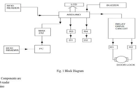
[image:1.612.78.523.412.697.2]II. BLOCKDIAGRAM
Fig. 1 Block Diagram
The main Components are 1) RFID reader
2) Arduino
A. Theft detection circuit
[image:2.612.154.449.164.367.2]Starting from the RFID reader, Two RFID readers are connected. One at the door side and other one near the PC, First RFID reader which is at door side is connected to the Arduino. And other is connected to the PC both the readers read the number of tags on book. Now it requires some device that it compares both the data and tells whether the book is issued or not. For this purpose MAX 232 Comparer is connected between Arduino and PC. If both data are same then no issue he/she can get book if it is not in case signal is send to the Arduino for activation of buzzer. This system is for theft detection purpose.
Fig.2 Theft Detection Circuit
B. Switching Circuit
Another system is On-Off switching of devices in library. It requires each relay for each device. It is connected to the Arduino and it works as per it is programmed in the Arduino.
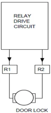
C. Door Lock System
Relay Driver circuit is connected to the two relays. Here we required two relays for “Closing” and “Opening” of door. Both relays are connected to the motor as shown in fig. 3 and relay driver circuit is connected to the Arduino for working as per programmed schedule.
[image:2.612.260.345.513.698.2]III.COMPONENTS
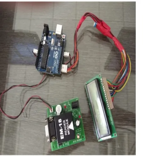
A. RFID Reader
The reader used in this system is EM 18 RFID reader. It read 125 KHz tag. In this system we are using two RFID Reader– one on the door and second at the counter. If any student doesn’t follow the process of issuing the book then the another RFID reader which is placed on the door is helpful to detect the theft, as there is a buzzer provided with the RFID reader, when that student passes through door buzzer will get buzz, so that we easily detect the theft as compare to CCTV system. The operating range of EM18 RFID reader is 10-15 cm. The operating frequency of EM18 RFID reader is 12 KHz. The current rating is less than 50 mA. The voltage range is 3.3V to 5.5V. As there is coil placed inside the EM18 RFID reader it radiant the 125 KHz frequency through coil & when the tag is swap over it then coil get energies.
B. Arduino
The Arduino UNO is an open-source microcontroller board based on the Microchip ATmega328P microcontroller. The board is equipped with sets of digital and analog input/output (I/O) pins that may be interfaced to various other circuits. The board has 14 Digital pins, 6 Analog pins, and programmable with the Arduino IDE (Integrated Development Environment) via a type B USB cable. It can be powered by a USB cable or by an external 9 volt battery, though it accepts voltages between 7 and 20 volts.
1) Technical Specifications
a) Microcontroller: Microchip ATmega328P [7] b) Operating Voltage: 5 Volt
c) Input Voltage: 7 to 20 Volts
d) Digital I/O Pins: 14 (of which 6 provide PWM output) e) Analog Input Pins: 6
f) DC Current per I/O Pin: 20 mA g) DC Current for 3.3V Pin: 50 mA
2) Pins: General function pins
a) LED: There is a built-in LED driven by digital pin 13. When the pin is HIGH value, the LED is on, when the pin is LOW, it's off.
b) VIN: The input voltage to the Arduino/Genuino board when it's using an external power source (as opposed to 5 volts from the USB connection or other regulated power source). You can supply voltage through this pin, or, if supplying voltage via the power jack, access it through this pin.
c) 5V: This pin outputs a regulated 5V from the regulator on the board. The board can be supplied with power either from the DC power jack (7 - 20V), the USB connector (5V), or the VIN pin of the board (7-20V). Supplying voltage via the 5V or 3.3V pins bypasses the regulator, and can damage the board.
d) 3V3: A 3.3 volt supply generated by the on-board regulator. Maximum current draw is 50 mA. e) GND: Ground pins.
f) IOREF: This pin on the Arduino/Genuino board provides the voltage reference with which the microcontroller operates. A properly configured shield can read the IOREF pin voltage and select the appropriate power source or enable voltage translators on the outputs to work with the 5V or 3.3V.
g) Reset: Typically used to add a reset button to shields which block the one on the board.
3) Special Function Pins: Each of the 14 digital pins and 6 Analog pins on the Uno can be used as an input or output, using pinMode(),digitalWrite(), and digitalRead() functions. They operate at 5 volts. Each pin can provide or receive 20 mA as recommended operating condition and has an internal pull-up resistor (disconnected by default) of 20-50k ohm. The Uno has 6 analog inputs, labeled A0 through A5, each of which provide 10 bits of resolution.
a) Serial: pins 0 (RX) and 1 (TX). Used to receive (RX) and transmit (TX) TTL serial data. These pins are connected to the corresponding pins of the ATmega8U2 USB-to-TTL Serial chip.
b) External Interrupts: pins 2 and 3. These pins can be configured to trigger an interrupt on a low value, a rising or falling edge, or a change in value.
d) SPI(Serial Peripheral Interface): 10 (SS), 11 (MOSI), 12 (MISO), 13 (SCK). These pins support SPI communication using the SPI library.
e) TWI(Two Wire Interface): A4 or SDA pin and A5 or SCL pin. Support TWI communication using the Wire library.
f) AREF(Analog REFerence): Reference voltage for the analog inputs.
C. 16*2 LCD Display
An LCD is an electronic display module which uses liquid crystal to produce a visible image. The 16×2 LCD display is a very basic module commonly used in DIYs and circuits. The 16×2 translates o a display 16 characters per line in 2 such lines. In this LCD each character is displayed in a 5×7 pixel matrix.
D. Relay
What is relay?
A relay is an electromagnetic switch operated by a relatively small electric current that can turn on or off a much larger electric current. The relays can work either as switches (turning things on and off) or as amplifiers (converting small currents into larger ones). The advantage of relays is that it takes a relatively small amount of power to operate the relay coil, but the relay itself can be used to control motors, heaters, lamps or AC circuits. In "normally open" (NO) relay: the contacts in the second circuit are not connected by default, and switch on only when a current flows through the magnet. In "normally closed" (NC; the contacts are connected so a current flows through them by default) and switch off only when the magnet is activated, pulling or pushing the contacts apart. Normally open relays are the most common.
IV.LCDINTERFACING
LCD interfacing is one of the important part of this project. It connects LCD with Arduino UNO.
[image:4.612.70.325.369.618.2]
Fig. 4 LCD Interfacing
In interfacing we uses 16*2 LCD Display and Arduino Uno. Pin 11,12,13,14 of LCD are connected to pin 5,4,3,2 of Arduino. Pin 4 and 6 of LCD are connected to pin 12, 11 of Arduino. 5 no pin of LCD is grounded.
A. ULN2003 IC
B. Pull Up Resistor
Pull up resistor used in proposed system consists of 9 pins out of which 8 are resistances and one is common one terminal of resistances is joint together and given to common terminal. 8 resistors are connected to pin 1 to 8 of IC. It is used to maintain constant supply if 5V to IC.
V. PROGRAM
#include<LiquidCrystal.h> LiquidCrystal lcd(12,11,5,4,3,2); int inbyte=0;
int count=0; void setup() {
pinMode(6,OUTPUT)); pinMode(7,OUTPUT)); digitalWrite(6,LOW); digitalWrite(6,LOW); lcd.begin(16,12); lcd.print(“RFID LIBRARY’); lcd.setCursor(0,1); lcd.print(“MGMT SYSTEM”); Serial.begin(9600); delay(1000); lcd.clear(); }
void loop() {
VI.SOFTWARES
A. Proteus Software
The Proteus design suit is a proprietary software tool suite used primarily for electronic design automation. In this system the Proteus Software is used to create schematics and electronic prints for manufacturing printed circuit boards(PCB).
B. Arduino Software
The open-source Arduino Software (IDE) makes it easy to write code and upload it to the board. This software can be used with any Arduino board. When the Uno is connected to either a computer running Mac OS X or Linux, it resets each time a connection is made to it from software (via USB).
VII. CONCLUSION
RFID is one of the most recent trends in modern academic libraries because of its helpful features like faster, required less manpower, time saving device, providing security to the documents etc. RFID is inevitable technology for making libraries future ready. RFID in the library speeds up book borrowing, monitoring, books searching processes and thus frees staff to do more user-service tasks. The most efficient and useful feature provided by RFID is that its implementation solves the most common problem of library, theft detection, searching the missing books and other documents. These applications can lead to significant savings in labor costs, enhance customer service, lower book theft and provide a constant record update of new collections of books. Thus, feasibility score of establishing a Radio Frequency Identification System (RFID) for establishment of security system is higher than medium.
REFERENCES
[1] Mr. Sunil Assistant Librarian, Chandigarh University, Dr. Nitish Ojha Assistant Professor Chandigarh University, Mohali, Punjab. “Radio Frequency Identification (RFID) Technology in Library: Advantages and Issues” Proceedings of the Second International Conference on Inventive Systems and Control (ICISC 2018).
[2] Prof. Ganesh K.Yenurkar1 Prof. Rajesh K. Nasare2 Prof. Sushil S. Chavhan3 Information Technology, YCCE Computer Science & Engineering, RGCER Information Technology, YCCE Nagpur, India Nagpur, India Nagpur, India. “RFID based Transaction and Searching of Library Books” IEEE International Conference on Power, Control, Signals and Instrumentation Engineering (ICPCSI-2017).
[3] Santhosh Goud Sammeta university librarian department of library and information science amity university Dubai, UAE. Sahith Reddy Madara Undergraduate Research Scholar Department of Aerospace Engineering Amity University Dubai, UAE. “Recent trends in RFID technologies and its impact on universities” [4] Hooryeh Naji-Esfahani M. Sc. Student in Dept. of LIS, Islamic Azad University (IAU), Khuzestan Science and Research Branch. “Feasibility Study of