Comparative Analysis of Teaching methods in
Electrical Engineering Courses – A Case Study
A .S.Viswanathan1, M. Mahendran2
Department of Electrical & Electronics Engineering Sri Chandrasekharendra Saraswathi Viswa Mahavidhyalaya, Tamil Nadu, India
Abstract: Global Education and Learning scenarios are seeing a swift and continuously evolving and changing after the advent of computers and internet. The usage of computing tools like software’s and embedded hardware’s in teaching and learning plays a major role in providing simplified learning environment. These tools provides ease of learning and understanding the electrical and electronics circuits and its functionality for enhanced concept and technical learning in electrical engineering. Some of the reputed software’s used across the universities are MATLAB, PSIM, Lab view, Multisim, Mi-power, PSCAD, Magnet and Spice based tools.
Keywords: Electrical engineering, teaching, learning, education, rectifier circuits, software’s
I.INTRODUCTION
Teaching engineering is not easy for educators in the Universities and educational institution across the globe, especially electrical engineering. Novel teaching methods and techniques are required in order to provide better delivery of the course content to the students which will in turn provide better and in-depth knowledge of the concepts. With the invention, advancements and use of the World Wide Web or internet, in synchronisation with evolving information and communication tools, e-learning has become an important part of teaching/learning processes in the Universities. Ease of learning, flexibility, trial and error analysis, mathematical computing on data’s, repetitive learning made software based e-Learning becomes a modern day alternative to traditional teaching methods like board and easel teaching. It is evident that computer aided design based software’s are helpful not only in the analysis of the complex circuits, but as well in teaching engineering students. As far as the electrical and electronics engineering courses are concerned the subject matter is conceptual and complex to understand – U cannot see the flow of current like flow of water. Students cannot visualise how current flows in a circuit or how a ac voltage is converted to dc voltage in a mobile charger. Across the world, the teachers are using the software’s like MATLAB, Labview, Multisim and PSIM to explain the concepts in a lucid way practically. In our department a study was made with students to understand their learning outcome of electrical and electronics engineering concepts with various teaching methods like board and easel, PowerPoint slides and simulation study using software’s. The example topic we have chosen to teach is the main component of the mobile charger which is an AC to DC Bridge or a rectifier circuit model.
II.AC-DC CONVERTOR
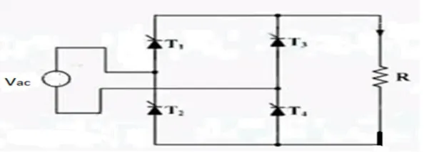
[image:1.612.169.466.595.702.2]Rectifier is a circuit which converts ac signal to dc. The supply power is 230 VAC and the Mobile phone circuits operate with dc supply. Hence it needs a conversion from AC to DC which is achieved by using a rectifier circuits. Rectifier circuit can be controlled circuit based on SCR or uncontrolled one by the use of diodes. For the case study purpose we used a SCR based rectifier circuit. In a day to day life, most of the electronics like TV, Mobile phone, UPS, invertors, Computers, power supply used rectifiers as one of its components. The circuit diagram and the basic operation of the circuit is given below.
The single phase fully controlled rectifier consists of 4 SCRS connected in the bridge form. When the supply is ON and the firing or gate signals are given to thyristors, the circuit operates and produces output. The Turn-off of the device happens generally, when the current through the device reaches zero or the supply reaches natural zero and the device gets reverse biased.
A. During positive half cycle
The Supply is in positive half cycle of sinusoidal input;
At a time period t = 0. Thyristors T1 & T4 are ON due to forward biasing and T2 and T3 are in off mode due to reverse bias. T1 and T4 won’t conduct.
At a time period t = α, firing or gate signal is given to the Gate terminal of the SCR. At this time junction breakdown happens and the thyristors T1 and T4 conducts
Vo = Vac
=
=
At a time period t = π, the supply reaches natural zero and hence T1 and T4 turns reverse biased and hence don’t conduct
B. During Negative Half Cycle
The Supply is in the negative half cycle of sinusoidal input;
At a time period t = π. Thyristors T2 & T3 are ON due to forward biasing and T1 and T4 are in off mode due to reverse bias. T2 and T3 won’t conduct.
At a time period t = π+α, firing or gate signal is given to the Gate terminal of the SCRs T2 and T3. At this time junction breakdown happens and the thyristors T2 and T3 conducts
Vo = Vac
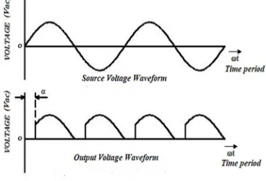
[image:2.612.218.409.433.563.2]At a time period t = 2π, the supply reaches natural zero and hence T3 and T2 turns reverse biased and in off mode and the cycle repeats. The waveform explaining the operation is given below in Fig.2.
Fig. 2 : Single Phase Full Bridge Rectifier – Supply and Output Voltage Waveform
The above circuit is taught to students using all the three means and the feedback is collected and analysed for the study purpose.
III. EVALUATION METHODOLOGY
As this circuit is taught in Power Electronics Course for the III year B.E. students, from our department we have selected 14 students for conducting the study including both genders with 8 males and 6 females. The three modes of teaching is used to explain the circuit operation, one mode each day. A feedback form is created with prepared questionnaires and given to students at the end of the third day to fill.
IV. PROCEDURES
A. Board and Easel Method
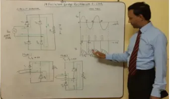
[image:3.612.232.403.146.246.2]This is a classroom based teaching Fig.3. Here the circuit and the waveforms of the rectifier circuit are drawn on the board using marker. Drawing any power electronics circuits with waveforms eats lots of time in a 1 hr time period of the class. For explaining the circuit the firing angle taken was approximately 45 degrees and the waveforms are drawn accordingly.
Fig. 3: Board writing image from the classroom
If we want to show to students at a different firing angle let’s say at 90 degree or 120 degree, you have to erase and re draw the circuit as the size of the board is also small. Hence we have to explain orally and students have to visualise the explanations. Hence explaining power electronics circuits over the board is a cumbersome and time killing tasks but the advantage is students can learn the way to draw the waveforms which will be useful for their exams.
B. PPT Slides Based Presentation Method
This is a smart class room based teaching. Today any teaching using computing facilities are called smart teachings. Power point slides based presentation - Fig.4. can provide better visuals and save time for explanations. The teaching materials and the course content are prepared prior to the classes. The students are invited to the smart class room for the PPT based learning’s. Using PPT slides saves time a teacher spent on drawing the waveforms, providing simplified teaching to explain the working principles of single phase Full bridge rectifier, We felt the hand practice in waveform drawings are not as effective like board drawings, where the students draw along with the teacher. It is difficult for the below average students to follow.
Fig 4: PPT Presentation captured image from classroom
C. Software Simulation Methods
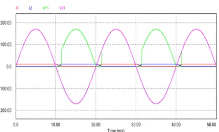
[image:3.612.158.453.437.585.2]Fig 5: PSIM Software based Full bridge Rectifier
Fig 6: PSIM Software based rectifier circuit - waveform
V.CASE STUDY FINDINGS AND DISCUSSION
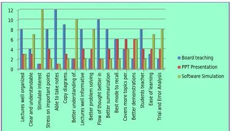
The participating students were explained about the objective of the case study and assured secrecy and also instructed to mark apt teaching modes for each question in the questionnaire form and give their overall opinion regarding the best teaching mode they preferred. Students were asked to mark in their preferential order from 1 to 3. All the students give their preference for all the 17 test parameters. Most preferred mode (marked 1st) is alone selected for analysis purposes. Data were entered in excel and were analyzed. Results are also expressed in percentages and shown with the help of bar diagram and pie chart Fig.7 & Fig 8.
[image:4.612.78.525.305.574.2]S. No Parameters Board teaching PPT Presentati on Software Simulati on Board teaching (%) PPT Present ation (%) Software Simulati on (%)
1 Lectures well organized 8 3 3 57.14 21.43 21.43
2 Clear and understandable 4 3 7 28.57 21.43 50
3 Stimulate interest 1 1 12 7.14 7.14 85.71
4 Stress on important points 8 4 2 57.14 28.57 14.29
5 Able to take notes 12 1 1 85.71 7.14 7.14
6 Copy diagrams /waveforms easily 9 3 2 64.29 21.43 14.29
7
Better understanding of subject
content 2 2 10 14.29 14.29 71.43
8 Lectures well informative 8 4 2 57.14 28.57 14.29
9 Better problem solving 2 4 8 14.29 28.57 57.14
10 Flow of thought better in 10 2 2 71.43 14.29 14.29
11 Better summarization 8 4 2 57.14 28.57 14.29
12
Best mode to recall important
points 6 6 2 42.86 42.86 14.29
13 Covers more topics per lecture 4 6 4 28.57 42.86 28.57
14 Better demonstrations 2 6 6 14.29 42.86 42.86
15
Students teacher interaction better
in 8 4 2 57.14 28.57 14.29
16 Ease of learning 3 4 7 21.43 28.57 50
17 Trial and Error Analysis 2 4 8 14.29 28.57 57.14
[image:5.612.50.560.62.452.2]Average 40.76 25.63 33.61
Table 1: Students Opinion between Board teachings, PPT Presentation & Software Simulation Approach
Fig. 7: Percentage distribution of parameters in board teaching, PowerPoint teaching, software simulation methods
[image:5.612.84.534.467.722.2]Fig 8: Pie diagram showing overall preference of students between the 3 teaching modes
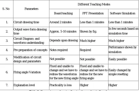
A comparison on the study of the circuit operation w.r.t three methods are given below in the table.
S. No Parameters
Different Teaching Modes
Board teaching PPT Presentation Software Simulation
1. Circuit drawing time Around 2 minutes Less than 1 minutes Less than 1 minutes
2. Output wave form drawing
time Approx. 5-10 minutes Shown by fig.
In few seconds based on simulation time
3. Circuit Diagram and
waveform understanding Depends upon drawing Much higher Much higher
4. Pre-preparation of concepts Notes required Required Performance shown by simulation
5. Modification of circuit
design and parameters Not possible Not possible Easily possible
6. Firing angle Variation
Fixed and unable to change and we have to redraw the waveforms for the new firing angle
Fixed and unable to change and we have to redraw for the new firing angle
Easily changed by simple resetting
7. Explanation level Practicality is less Higher Higher
Table 2: Comparison on learning the circuit operation in 3 modes
In this study, most students selected board teaching is the best teaching aid when compared to PPT and software simulation teaching method. Table.1 shows students opinion for all 17 parameters against all the three teaching modes. The overall preference of students toward the best teaching aid was blackboard with 40.76%, followed by software simulation study with 33.61% preference and remaining 25.63% preferred PPT teaching method [Figures 1 and 2].
Board teaching
PPT Presentation
[image:6.612.79.535.361.660.2]VI. GENERAL DISCUSSION ON 3 MODES OF TEACHING
The teaching learning process in engineering has to be redefined in pace with the changing needs of the learners and changing trends in education. Hence, if the needs of the learners are considered while during teaching, the process of teaching learning can be made effective. In this case study, we tried to find out the needs of the students who are the learners through the feedback on the topic in all the 3 modes of teaching from the power electronics course.
Learning and teaching are continuous processes which can be demonstrated with learners ability to express their gained knowledge, realisation, facts, and new skills.[10,11] A good teaching process needs a good communication skills for exchanging ideas and information. The major limitation of class lectures is sometimes the students may not active in the class to listen and understand and may feel uninterested and sleepy. Class teaching can be very effective if visual aids are used.[12]. Board and easel is the most commonly used visual aid as it gives ease of access and relatively simple to use. With Marker or chalk, board, and duster which are easily affordable you can have a class room teaching.. Students will have better retention on the course concepts, if they take notes during the class teaching. Some of the drawbacks like un comfort feeling in taking notes, losing the continuity may be avoided by the students paying full attention. Also Teacher has to prepare handouts of the course content to be taught before the session starts, which will be of great useful for the learning students to follow if given in advance.
In PPT slides presentation, the teacher prepares slides with typed information or photographic visuals or even audio and video information of the course content. The handouts of the slides can be given to students before the class starts either as printed material or as a softcopy. This also reduces student’s effort in taking notes during the teaching ad attention of students is retained in a bigger way. The computers or laptops, projectors are needed for this method of teaching. The lecturer shows the information in the slides and explains the important points during the lectures. The lecturer has to work in preparing slides well in advance. PPT mode gives good understanding of the topics as the coverage and flow of subject are limited within a fixed number of slides. The teachers can also use the slides as memory aids, which decrease the mental strain of the teachers. The teacher always has a chance to recollect the information by seeing the slides.
Software developments and advancements made teaching and learning process a much easier. The advantage of using simulation software in the classroom and laboratories is that it offers students, a wide variety of options for technical learning, solving the complex problems with ease and make the learning process joy full, provided you have enough information on handling the software’s, Providing better visual operation of electrical and electronics circuits, It saves the time for the faculty to cover more concepts, with user-friendly interface software’s has the capability to simulate any type of power electronic circuits. Employment opportunities are more if the students have good software skills especially in engineering field. Another advantage of simulation based study is that they provide users with practical output, when designing real world systems. This allows the designer to validate the design before the real electronic system is actually developed. Simulations have the advantage of allowing the students to reset the circuit design and try alternative design approach or to make modifications to parametric data to get needed results.
VII. CONCLUSION
This case study compares board and easel with PPT slides presentation method and software simulation method for teaching concepts in power electronics. As power electronic circuits and control systems are getting more complex today, the simulation provides a better way to learn than the other 2 modes, however a simple circuit used here for test case purpose, hence the students might have more preference towards Board teaching. Traditional board teaching method cannot be completely neglected. In this case study board teaching still stands at the top. However, the teaching can be made more effective by combining it with other 2 modes of teaching.
REFERENCES
[1] Bhimbra, P. S., Power Electronics, 4th Ed., Khanna Publication, 2007.
[2] Muhammad H. Rashid, Power electronics, circuit devices and application, 3rd Ed., Pearson education Inc., 2007. P.C. Sen, Power electronics, Tata
McGraw-Hill publishing company, 2008.
[3] BK khanchandani, Power electronics, Tata McGraw-Hill publishing company, 2008.
[4] Rajesh Verma, Ashu Gupta and Kawaljeet Singh, (2008), “Simulation Software Evaluation and Selection: A Comprehensive Framework”, J. Automation &
Systems Engineering, pp. 221-234.
[5] Kapilevich, B. Shaibon, H. ; Rahman, T.A. “Simulation modeling in electrical engineering: experience of teaching in University Technology of Malaysia”,
IEEE First International Conference on Multi-Media Engineering Education Proceedings, 1994., pp. 92-98, July 1994.
[6] W. W. Cooley, P. Klinkhachorn, R. L. McConnell, and N. T. Middleton, (1991) “Developing professionalism in the electrical engineering classroom,” IEEE
Trans. Educ., vol. 34, pp. 149–154.
[7] EuzeliCipriano dos Santos, Edison Roberto Cabral da Silva, (2013), “Power Block Geometry Applied to the Building of Power Electronics Converters” IEEE
[8] Abramovitz, (2011) “Teaching behavioral modeling and simulation techniques for power electronics courses,”
[9] IEEE Trans. Educ., vol. 54, no. 4, pp. 523–530,.
[10] M. Prince and R. Felder, “The many faces of inductive teaching and learning,” J. College Sci. Teaching, vol. 36, pp. 14–20, Mar. 2007.
[11] Sameer Khader, “The Application of PSIM & MATLAB/SIMULINK in power electronics courses”, Conf. "Learning Environments and Ecosystems in
Engineering Education"; IEEE Global Engineering Education Conference (EDUCON) – April 4-6, 2010, Amman, Jordan.
[12] C. A. Canesin, F. A. S. Gonçalves, and L. P. Sampaio,(2010) “Simulation tools for power electronics courses based on Java technologies,” IEEE Trans. Educ.,
vol. 53 (4), pp. 580–586.
[13] Hemant Mehar, (2012) “Software Application In Under Graduate Electrical Engineering Education”, International Journal of Engineering Research &
Technology (IJERT), Vol. 1 (10).
[14] Hemant Mehar, (2012) “MATLAB Simulation Techniques in Power Electronics”, IEEE Technology and Engineering Education (ITEE), vol. 7 (4), pp. 62.
[15] Hemant Mehar, (2013), “The Case Study of Simulation of Power Converter Circuits Using Psim Software in Teaching”, American Journal of Educational
Research, , vol. 1 (4), pp. 137-142, May.
[16] Kevin M Passino. Teaching Professional and Ethical Aspects of Electrical Engineering to a Large Class. IEEE Trans. Educ. 1998; 41(4): 149-154.
[17] Michael Prince, “Does Active Learning Work? A Review of the Research,” Journal of Engineering Education, pp. 223-231, July 2005.
[18] Dwight F. Mix and Juan Carlos Balda, “ELEG 1003–Introduction to Electrical Engineering: An Approach to Motivate and Teach EE Freshmen,” Proceedings