An Ad-Hoc Low Cost Wireless Sensor Network for Smart
Gas Metering
Oscar Rorato1, Silvano Bertoldo1, Claudio Lucianaz1, Marco Allegretti2, Riccardo Notarpietro1 1Department of Electronic and Telecommunications (DET),Polytechnic of Turin, Turin, Italy
2National Consortium of Universities for the Physics of Atmospheres and Hydrospheres (CINFAI), Local Unit c/o, Polytechnic of Turin, Turin, Italy
Email: [email protected], [email protected]
Received January 24, 2013; revised February 22, 2013; accepted March 4, 2013
ABSTRACT
The monitoring of power consumption has become of a great interest in recent years as well as the innovative technolo-gies available to realize Wireless Sensor Networks (WSNs) have experienced a great growth. While smart metering technologies for electric energy are already established, as sensors power supply comes directly from power lines, WSN nodes for gas metering should necessarily be equipped with long life batteries. The presented work describes a new prototypal low cost WSN designed ad hoc for gas smart metering. The network has a star topology: each sensor node can be completely integrated with standard reed relay gas meter, and it is capable to measure the gas consumption. The information is sent to the central node (the Access Point, AP) through an RF links. The sensor nodes have been de-signed with custom electronics and a proprietary firmware, in order to work with a common 3.6 V lithium battery which is able to ensure a life period of about 10 years for each node. Only the AP must be connected directly to electric power. The AP is connected through the RS-232 interface to a control embedded PC equipped with a LAMP (Linux, Apache, MySQL, PHP) framework: it stores all the information coming from each node in a coherent database and allows au- thorized users to check the network status using a web interface. The WSN is self-learning and it is capable to detect new nodes joining the network without altering the normal operative flow. Moreover e-mail and SMS alerts can be ac- tivated to alert if a node is disconnected from the network or some problems occur. A first prototype of the WSN has been already tested achieving good results.
Keywords: WSN; Smart Grid; Smart Metering; Gas Metering; Energy Metering; Electronic Board; Ad-Hoc Designed
Board; Low Cost
1. Introduction
Wireless Sensor Networks (WSNs) have become very important in recent years because of their numerous pos- sible applications. They are used for collecting, storing and sharing data, for environmental monitoring applica- tion [1,2], surveillance purposes [3], sport performance evaluation [4], agriculture [5], home automation applica- tions and, very important and topical, they are increas- ingly used for energy management.
The Smart Grids, which are particular WSNs devoted to energy management, are emerging as a convergence of information technology and communication technology with power system engineering and metering technolo- gies. A more detailed definition can explain better what are the “Smart Grids” today emphasizing their relevance. They can be defined as networks that can intelligently integrate the actions of all users connected to them using digital technologies. Basically their goal is a moderniza- tion of already existing energy grids with ICT technolo-
gies, joining power-delivery systems and customers, and allowing a two-way communication between them. A paper of Panajotovic et al. [6], presents a very detailed
description of the state of the art of the smart grid and their close relationship with ICT.
The Smart Grids will have a key role in the transfor- mation of the current functionality of the energy distribu- tion system, aiming both to offer a user-oriented service and to help energy distribution companies. They will help European countries to achieve the so called objec- tives “20/20/20” (Horizon, 2020) the next European framework program for research and innovation.
Usually the words “Smart Grids” are referred to the elec- trical distribution systems because the grids usually have strict power requirements. By using more modern tech- nologies for WSN it is also possible to implement Smart Grids for different energy sources such as the gas energy. A new experimental and prototypal Wireless Sensor Network has been completely designed, realized and test- ed as an ad-hoc smart grid for gas metering able to give to gas operators a simple and cheap tool to keep under control the costumers gas consumption.
In the next paragraphs all aspects of the prototypal smart grid will be described.
2. General Description of the Grid for Smart
Gas Metering
The smart grid for gas metering has been designed with a master-slave architecture and star topology. A central node, called Master Node or Access Point (AP), receives data coming from all the peripheral nodes and dialogues with an embedded control PC. It has to be noted that each slave nodes communicates only with the master node with a unidirectional link.
The control PC is a common commercial embedded PC which can be connected to internet using either a GPRS router or a wired internet connection. It allows both locally and remotely authorized users (e.g. the gas company which delivers the service) to control the gas consumption. Moreover the PC stores all the data coming from the sensor node in a dedicated database and can send SMS and e-mail alerts, if such functionalities are turned on. Both the control PC and AP node are con- nected to power lines because of their high computa- tional load.
Each slave node is directly connected to a gas meter equipment, which is almost never connected to power lines. To ensure a life period of almost 10 years (avoid- ing a too frequent battery replacements by maintenance workers), the nodes’ electronics have been designed to have an almost irrelevant current consumption and they can be fed up by a common 3.6 V lithium battery.
The sensor node has been designed in order to receive information coming from a commercial pulse transmitter. It is connected to a common commercial gas meter in order to count the pulses detected by its reed relay switch. In fact, even if some high resolution electronic gas meter systems have been experimentally realized [8], most gas meters used for residential purposes are still using me- chanical diaphragms technology connected to reed pulse gas meter. The number of counted pulses are sent to the AP using the standard Wireless M-BUS protocol [9]. Knowing the correspondence between a single count and the gas consumption it will be possible to evaluate the gas consumption by each meter installed by the custom- ers.
On the basis of such information, each other operation (e.g. suggest a reduction of the gas consumption, alert that the consumption are different from the average ones… ) can be performed in future developments of the prototypal wireless sensor network.
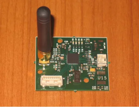
3. Sensor Node Description
The sensor node (Figure 1) is developed to perform the
following tasks:
Reading pulses from gas meter equipments;
Storing the temporary number of counted pulses on local memory waiting to send to the AP;
Managing Wireless Meter Bus protocol for download data to the AP;
Error handling.
The system on chip (SoC) used for the node of the smart grid is the Texas Instruments CC430F5135: it in- tegrates in a single solution both the microcontroller and the radio, thus reducing costs and power consumption. The radio can operate in different frequency bands (300 - 348 MHz, 389 - 464 MHz, 779 - 928 MHz) with very little firmware and hardware modifications. The develo- ped smart grid prototype operates a 868 MHz.
[image:2.595.309.538.545.722.2]The board power consumption depends on the chosen operating modes. In particular it is very sensitive to the selected output power (up to a maximum of 10 dBm) which cause a consumption to a few tens of milli-Am- peres [10]. In the described prototype, low power firm ware techniques have been adopted in order to properly managed the board, reducing the power consumption, keeping the microcontroller in the so called “Low Power Mode” as long as possible, since in that condition the amount of absorbed current is equal to a few micro- Amperes. It is possible to achieve a theoretical durations of 10 years using commercial standard lithium batteries of 3.6 V.
3.1. Reading Pulses from Gas Meter Equipments
The electronic boards for the described smart grid have been completely designed: they have two interfaces to manage both open collector output than reed relay switches. For the smart grid, only the second interface has been used (Figure 2).
The microcontroller acquires the pulse thanks to the right setting of the dedicated pin. The pulse trigger a soft- ware interrupt able to update the pulse count.
3.2. Storing Pulse on Local Memory
The pulses read by the electronic board are stored on the local flash memory of the microcontroller waiting to be send to the AP. The available memory size is enough for the purposes of the described smart grid.
3.3. The Communication Protocol
A detailed description of the wireless metering protocol state of art is reported in a work by A. Sikora et al. [11].
Anyway the Meter Bus (M-BUS) protocol and the wire-less version (Wirewire-less M-BUS or WM-BUS) are the “de-facto” standard for all the smart metering grid.
The M-BUS protocol is the most common standard used for the so called Automatic Meter Reading (AMR) implementation, very useful for remote energy meter reading. It is based on European standard EN 13757-2 (for physical and link layers) and EN 13757-3 (for appli- cation layer). The M-BUS can be used in different to- pologies of Smart Grids, including the star topology used for the presented network. When interrogated, the meter nodes (the slave nodes) send the data to a concentrator (the master node devoted to receive and manage data from each slave node) that can be also remotely placed if an internet connection is available.
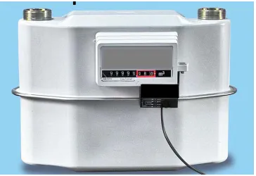
[image:3.595.82.264.564.689.2]The WM-BUS standard is another European standard defined in EN 13757-4 (for physical and data link layers) and in EN 13757-3 (for the application layer). It defines
Figure 2. Example of common gas metering system. The black box is the commercial pulse transmitter which is connected to the sensor board of the smart grid shown in Figure 1.
different possibilities of communication between remote meters and mobile devices, stationary receivers, and data collectors and storage devices [12].
The WM-BUS standard is designed to give a long bat- tery life for grid nodes powered with batteries, to avoid often battery replacements during the normal life time of a network node. Moreover it has to be noted that the pre- sented smart grid for gas metering does not require the complete version of the WM-BUS protocol which has more complete and complex features [13]. It is sufficient a limited version which is currently in use in a lot of ex- perimental and prototypal grids and which can be freely downloaded from the web. It is only necessary to adapt such protocol to the system on chip used in the custom realized electronic boards, thus reducing the realization costs of the WSN.
Among the different modes available with WM-BUS protocol, the described network uses the Stationary Mode (S-Mode), which allows an unidirectional link between meter nodes and the AP. It is in fact only necessary that each sensor node sends its data to the central node, without waiting any acknowledgement answer.
The S-Mode defines a radio link type with the follow- ing characteristics:
Manchester data coding;
32.768 k baud typical;
868 MHz ± 100 kHz as operational frequency;
Typical receiver sensitivity of −105 dBm to ensure a BER of 10−2.
All the described characteristics, including the packet length, suit very well with the proposed WSN solution for smart gas metering.
To handle the WM-BUS protocol, dedicated firmware functions have been developed and integrated on the mi- crocontroller. A proprietary algorithm, based on the ap- proach “listen before talk”, has been developed to ma- nage and avoid the collision when more than one node want to transmits at the same time.
3.4. Error Handling
4. Central node Description
The central node is made up by the Access Point (AP) node, which is directly connected to the embedded PC. The communication between the AP and the embedded PC is performed through the standard RS-232.
4.1. The Access Point Node
To further reduce the production costs of the electronic boards, the hardware of the AP electronic board is the same of the one adopted for the meter nodes. In fact, even if the AP is the only node which uses the RS-232 standard, the interface has been placed on all the node to serialize the board production. It possible to substitute each node of the smart grid with another by only modi- fying the firmware.
The AP receives WM-BUS packets coming from each nodes and forwards each packets to the embedded PC.
4.2. The Embedded PC
The embedded PC performs four basic functions:
reception of the information acquired from the AP;
storage of node values in a coherent database, thus providing a database server;
representation of the network status on the web inter-face, thus providing a web server;
sending e-mails and SMS alerts if the dedicated func-tionalities are active.
All the functions are performed simultaneously while the PC is connected to internet through a GPRS router or a wired connection, if available.
The PC is equipped only with open source software and a LAMP platform is installed on it, in order to create an easy to use system, compliant with international stan- dards. The LAMP platform includes Linux (Debian 6.0) as operative system, Apache as web server, MySQL as database server and PHP as scripting and programming language. This is one of the most globally used frame- work and allow the prototypal grid to be a base for a fu- ture more complex system development.
The reception of the information on RS-232 interface is managed by an ad-hoc developed C software which stores the read values coming from each node in the da- tabase. It uses open source libraries and checks if a node is still connected to the smart grid (a node is assumed to be disconnected or not active if does not transmit any data for 10 minutes). The same software creates a spe- cific log file which allows to control the correct func- tioning of the network and the correct reception of the packet coming from the AP.
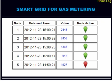
The web interface has been realized using both HTML and PHP languages. It is accessible only after an authen- tication procedure, and it is made up by two sections. The main section shows the last read values coming from
each node, with the corresponding timestamp, while a graphical indicator shows if a node is still active and connected to the smart grid (Figure 3). The second sec-
tion shows the last 10 rows of the log file and allows to have an immediate indication in case of network prob- lems (Figure 4).
If a node becomes disconnected from the smart grid or some problems occur, e-mail or SMS alerts are also sent by the AP to a list of selected addresses or phone num- bers. Such functionalities can be turned on or off using a configuration file editable by authorized users.
The database is made up by two tables: the first con- tains the information related to the smart grid nodes and the seconds contains the data related to the pulse detected by each sensor node and sent through radio channel to the central node (Figure 5 shows the implemented struc-
ture).
[image:4.595.307.538.375.543.2]The tables respect the referential integrity constraint. If a node is connected for the first time to the grid its inser- tion into the database is managed by well designed store procedures and triggers. Such triggers are activated be- fore the record containing the data read by the node is stored into the right table of the database. It is thus
[image:4.595.310.536.590.709.2]Figure 3. Example of web interface. It reports the informa- tion about each network node. In the reported situation node 5 is no longer connected to the smart grid.
Figure 5. Entity-relationship scheme for central node data- base.
possible to avoid writing specific C procedures to add a new node in the database, making the entire database more robust and efficient.
5. Test
A first experimental smart grid for gas metering, made by one AP connected to the embedded PC and 5 sensor nodes, have been tested in the laboratory achieving very good results. The WSN has proven to be “self-learning”, and each new node connected to smart grid has been correctly recognized and added into the database as soon as it has been turned on.
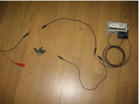
A massive stress test have been performed by con- necting each sensor node to a tool able to simulate the pulses coming from the commercial pulse generator connected to the gas meter (Figure 6). The sampling
time has been set to 1 minute, in order to have a large amount of data to be stored on the embedded PC of the central node. The simulated network has been kept “ope- rational” for almost 14 consecutive days. Each node sent to the AP an average of 18600 values (out of the theo- retically expected 20152). Details about data transmitted by each node and correctly managed by the simulated network are shown in Table 1.
Sampling interval equal to 1 minute is definitely ex- cessive in a real context of application of the smart grid for smart gas metering. It is more likely that each grid node will perform a sampling operation 4 times per day in order to allow the AP to receive 1460 packets per year. With 20152 packets received at the end of the test, a pe- riod of activity of the entire smart grid equal approxi- mately to 14 years (actually 13.8 years) was estimated.
[image:5.595.60.287.87.211.2]Experimental current consumption was very low in 4 out of 5 test nodes, in accordance to datasheet informa- tion, allowing a life period of each node of almost 10 years, as decided in designing stage. The higher current absorption of the fifth node is due to imperfections in the realization of electronic boards (e.g. not perfect compo- nents welding).
Figure 6. Smart grid node during the massive stress test connected to commercial pulse generator which will be connected to the gas meter in a real application.
Table 1. Percentage of correctly received packets from each node and managed by the entire smart.
Received packets
Percentage of correctly received packet
Node 1 18801 94%
Node 2 18716 93%
Node 3 18878 94%
Node 4 17748 88%
Node 5 18862 94%
Smart Grids 93005 92%
6. Conclusions and Outlooks
This paper presents a new prototypal low cost smart grid ad-hoc designed for gas metering.
All the hardware, the firmware, the software and the solutions are ad-hoc designed and developed for this purposes, paying particular attention to the overall cost reduction of the custom realized electronic board, which was designed to be compatible with the already available commercial gas metering equipments.
The present version of the prototypal smart grid stores into the database the number of pulses coming from the gas meter equipments and detected by each node.
All the tests performed in laboratory show that the de- veloped smart grid acquires information from comercial gas meter equipments with very few errors, assuring a good reliability of the systems.
[image:5.595.309.538.333.466.2]U000009.
In the future a complete experimental installation of the prototypal smart grid will be realized in order to test the wireless sensor network in a fully operative situation. Moreover it will also be possible to realize a specific pro- cedure to store in the database the amount of gas con- sumed by each user. Finally other services can be im- plemented to improve the gas metering grid and make it more complete and efficient.
7. Acknowledgements
The present paper represents the result of an experimen- tal activity promoted by the local operative unit of CIN- FAI (Consorzio Interuniversitario Nazionale per la Fisica delle Atmosfere e delle Idrosfere, www.cinfai.it) c/o DET (Department of Electronic and Telecommunications. www.det.polito.it) of Polytechnic of Turin, and develo- ped in cooperation with the Italian gas company Piceno Gas S.R.L. (www.picenogas.com).
REFERENCES
[1] C. Lucianaz, O. Rorato, M. Allegretti, M. Mamino, M. Roggero,/ F. Diotri, “Low Cost DGPS Wireless Net- work,” IEEE-APS Topical Conference on Antennas and Propagation in Wireless Communications (APWC), Tori- no, 12-16 September 2011, pp. 792-795.
[2] Gabella M., R. Notarpietro, S. Bertoldo, A. Prato, C. Lucianaz, O. Rorato, M. Allegretti and G. Perona, “A Network of Portable, Low-Cost, X-Band Radars,” In: J. Bech, Ed., Doppler Radar Observations—Weather Radar, Wind Profiler, Ionospheric Radar, and Other Advanced Applications, Intech, Rijeka, pp. 175-202.
[3] S. Bertoldo, O. Rorato, C. Lucianaz and M. Allegretti, “A Wireless Sensor Network Ad-Hoc Designed as Anti-Theft Alarm System for Photovoltaic Panels,” Wireless Sensor Network, Vol. 4, No. 4, 2012, pp. 107-112.
doi:10.4236/wsn.2012.44014
[4] T. Le Sage, A. Bindel, P. Conway, L. Justham, S. Slaw- son and A. West, “Embedded Programming and Real- Time Signal Processing of Swimming Strokes,” Sports Engineering, Vol. 14, No. 1, 2011, pp. 1-14.
doi:10.1007/s12283-011-0070-7
[5] M. Keshtgari and A. Deljoo, “A Wireless Sensor Network Solution for Precision Agriculture Based on Zigbee Technology,” Wireless Sensor Network, Vol. 4, No. 1, 2012, pp. 25-30. doi:10.4236/wsn.2012.41004
[6] B. Panajotovic, M. Jankovic and B. Odadzic, “ICT and Smart Grid,” 10th International Conference on Tele- communication in Modern Satellite Cable and Broadcas- ting Services (TELSIKS), Belgrade, 5-8 October 2011, pp. 118-121. doi:10.1109/TELSKS.2011.6112018
[7] R. E. Brown, “Impact of Smart Grid on Distribution Sys- tem Design,” Power and Energy Society General Meeting —Conversion and Delivery of Electrical Energy in the 21st Century, IEEE, Pittsburgh, 20-24 July 2008, pp. 1-4. doi:10.1109/PES.2008.4596843
[8] M. Tewolde, J. C. Fritch and J. P. Longtin, “High-Reso- lution Meter Reading Technique for Appliance Gas Us- age Monitoring for the Smart Grid,” 8th International Conference & Expo on Emerging Technologies for a Smarter World (CEWIT), New York, 2-3 November 2011, pp. 1-6. doi:10.1109/CEWIT.2011.6135876
[9] N. Anglani, E. Bassi, F. Benzi, L. Frosini and T. Traino, “Energy Smart Meters Integration in Favor of the End User,” IEEE International Conference on Smart Mea- surements for Future Grids (SMFG), Bologna, 14-16 November 2011, pp. 16-21.
doi:10.1109/SMFG.2011.6125773
[10] SoC with RF Core CC430F5135 Datasheet, Texas Instru- ment, 2012. www.ti.com
[11] A. Sikora, P. Villalonga and K. Landwehr, “Extensions to Wireless M-BUS Protocol for Smart Metering and Smart Grid Application,” Proceedings of the International Con- ference on Advances in Computing, Communications and Informatics (ICACCI ’12), ACM, New York, pp. 399-404. doi:10.1145/2345396.2345462
[12] K. Hariharasudhan, F. Colaianni, M. Sardo, S. Ramkumar and N. Kochhar, “Wireless M-BUS in Smart Grid Sce- nario,” Arrow Electronics.
http://components-asiapac.arrow.com