© 2019, IRJET | Impact Factor value: 7.211 | ISO 9001:2008 Certified Journal
| Page 1165
Smart Security System using Arduino and Wireless Communication
Raghavendra G S
1, Aakash Koul
21
Associate Professor, S. D. M College of Engineering & Technology, Karnataka, India
2
S. D. M College of Engineering & Technology, Karnataka, India
---***---Abstract - The development of technology in the field of Electronics has brought drastic changes in everyday life. The technology has made tremendous advances in variety of domain fields like medicine, telecommunication, automation and security. This paper demonstrates the working of a low cost, low power consumption wireless security system. We have proposed an intelligent security system that uses password based digital lock and ultrasonic sensor for theft detection and sends signal to indicate the theft using ESP8266 wireless communication technology. This paper proposes the overall framework of hardware and software design and methodology to implement the system.
Key Words: Arduino, Ultrasonic Sensor, digital lock, ESP8266
1. INTRODUCTION
With the emergence of new technology, security can be provided in a smarter way. This paper proposes Home security system and introduces many technologies for making the system installation easy and secure. Most of the system makes use of mobile communication like GSM [3] and Wi-Fi [2] for security systems. The Central Processing Unit for the proposed system is developed using the Arduino microcontroller which is a low cost and efficient controller used in many applications.
In this application, embedded system technology is combined with the wireless technology to provide password based digital lock [1], which is basically an access control system that allows only authorized persons to access a restricted area and the ESP8266 wireless communication technology for transmitting theft indication signals.
If entered password is wrong for more than 3 times then the output is extended such that it will transmit a signal to the owner so that the owner can make attempt to catch the thief. This system finds its application in many domains like houses, banks, vehicles and lockers etc., [10-13].
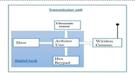
[image:1.595.319.553.184.315.2]The system consists of Hex keypad, ultrasonic sensor and ESP8266 which is connected to the microcontroller. The Fig - 1 describes the system with the help of block diagram.
Fig – 1: Block Diagram of Smart Security System
The Digital code lock or Hex Keypad [1] is a type of digital locks where a combination of digits/characters or both are used for locking and unlocking the lock. The crucial component of security in this system is ultrasonic sensor, normally being placed at window grill or door. It works by sensing the vibrations. The wireless communication system used in this system is ESP8266, which sends notification to the owner.
The system also uses microcontroller board such as Arduino along with the combination of ESP8266 and ultrasonic sensor to provide a complete security system.
2. HARDWARE REQUIREMENTS
The security system consists of following hardware:
Digital Code Lock
Arduino Board.
Ultrasonic Sensor.
ESP8266 chip.
2.1 Digital Code Lock
© 2018, IRJET | Impact Factor value: 7.211 | ISO 9001:2008 Certified Journal
| Page 1166
[image:2.595.105.216.132.245.2]switch on the corresponding device. The Fig - 2 shows the digital code lock.
Fig - 2: Digital Code Lock
2.2 Arduino Board
[image:2.595.367.497.274.330.2]Arduino [6] is a tool for making computers that can sense and control more of the physical world than your desktop computer. It's an open-source physical computing platform based on a simple microcontroller board and a development environment for writing software for the board. The Fig - 3 shows the Arduino board.
Fig - 3: Arduino Board
The Arduino can be used to develop interactive objects considering inputs from a variety of switches or sensors, and controlling a variety of lights, motors, and other physical outputs. The Arduino projects can be stand-alone, or they can communicate with software running on your computer (e.g. Flash, Processing, and MaxMSP.) The boards can be assembled by hand or purchased preassembled. Arduino simplifies the process of working with microcontrollers and also it offers some advantage to variety of users over other systems:
Inexpensive
Cross-platform
Simple clear programming environment
Open source and extensible software
Open source and extensible hardware
2.3 Ultrasonic Sensor
[image:2.595.81.241.374.502.2]Ultrasonic sensors [9] (also known as transceivers as they send and receive signals, but more generally called transducers) work on the similar principle to radar or sonar, which evaluate attributes of a target by interpreting the echoes from radio or sound waves respectively. The active ultrasonic sensors generate high frequency sound waves and evaluate the echo which is received back by the sensor, measuring the time interval between sending the signal and receiving the echo to determine the distance to an object. When there is a sensation, message is being sent to the mobile phone of the owner. The Fig - 4 shows the Ultrasonic Sensor.
Fig - 4: Ultrasonic Sensor
2.4 ESP8266 chip
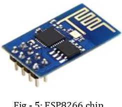
The ESP8266 is a low-cost Wi-Fi chip with full TCP/IP stack and MCU (Micro Controller Unit) capability. This small module allows microcontrollers to connect to a Wi-Fi network and make simple TCP/IP connections using commands. The low cost and the fact that there are very few external components on the module which suggests that application can use more in numbers as per need. The ESP8266 is an ESP8265 with 1 MB of built-in flash allows single-chip devices to connect to Wi-Fi. This module helps in the wireless communication for sending threats to the user. The Fig - 5 shows the ESP8266 chip.
Fig - 5: ESP8266 chip
3. SOFTWARE REQUIREMENTS
[image:2.595.375.497.519.626.2]© 2018, IRJET | Impact Factor value: 7.211 | ISO 9001:2008 Certified Journal
| Page 1167
Setup ( ): a function run once at the start of a program that can initialize settings.
Loop ( ): a function called repeatedly until the board powers off.
4. IMPLEMENTATION AND RESULTS
4.1 Implementation
The necessary steps to implement the smart security system are as follows:
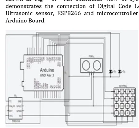
1. Firstly, all the hardware components are connected as shown in Fig - 6. The schematic view of system demonstrates the connection of Digital Code Lock, Ultrasonic sensor, ESP8266 and microcontroller i.e. Arduino Board.
Fig - 6: Schematic View of the system.
In Fig – 6, the hardware components are denoted as follows.
Arduino Board as Arduino UNO Rev 3
Digital Code Lock as Keypad
Ultrasonic sensor as Ping
LED’s as D1 & D2
ESP8266 as ESP8266
2. The program is initialized when the power is ON. At this point of time, the system is in its initial state as shown in Fig – 7 and the controller continuously scan the data from the keypad and whenever the password is entered through the digital keypad interfaced to the microcontroller.
Fig -7: Initial State of the System
[image:3.595.45.271.263.471.2]3. As the program starts, it will ask to input 4 digits as password. After the four digits are entered, the user is prompted to confirm password by pressing *. If any user enters the password and the password did not match then red LED blinks as shown in Fig - 8 and after 3 wrong attempts the message is sent to the owner.
Fig - 8: Red LED for wrong password.
4. If pressed keys match with the stored password then green LED blinks as shown in Fig - 9.
Fig - 9: Green LED for right password
© 2018, IRJET | Impact Factor value: 7.211 | ISO 9001:2008 Certified Journal
| Page 1168
Fig - 10: Notifying owner.
In the designed system, the functionalities of the keys in the Digital Code Lock are as follows:-
• Key * - used for unlocking the device. Input the correct four digit password and press * for unlocking.
• Key # - used for resetting the password. Just press # and press the new password for resetting the password.
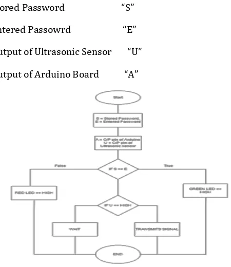
The Fig – 11 shows the Flow chart of the working system. The description of the flow chart is as follows:-
Stored Password “S”
Entered Passowrd “E”
Output of Ultrasonic Sensor “U”
Output of Arduino Board “A”
Fig - 10: Flow chart of the system
4.2 Results
The owner gets notified when:
1. An unknown person tries to break the system then ultrasonic sensor goes HIGH because of signal vibration.
2. Entered password does not match with the stored password.
When the entered password does not matches with the already stored password then the system excites the pin to which red LED is connected.
Whenever someone tries to break the system where ultrasonic sensor, the output pin of microcontroller to which ESP8266 has been connected gets excited, which leads to the further communication with owner.
The system uses LED as indicative element but other type of signaling elements like buzzer can be used.
5. CONCLUSION
This paper presents the design and the implementation of a Smart Security System for homes using Arduino and the Wireless communication using ESP8266 chip. A. The system has a user friendly interface which is easy to install and use. The system is low cost, consumes low power and provides high security.
6. FUTURE WORK
In future, smart security system can include an image processing tool at the entrance of the house. This system captures the photo of the person entering the password and compares the captured photo gets compared with the predefined image of the authorized user in the system. If the both images match, then the system operation takes place or else the access will be denied. This future design will enhance the security of the system by authorizing person as well as password and intruder cannot access the system even though he knows the password. The smart security system can be made more robust by enabling wireless transceiver modules to transfer other information such as voice and picture rather than just alarm signal [5].
REFERENCES
1. Annie P. O., Rahul A. P., Pranav V, Ponni S, andRenjithNadeshan, “Design and Implementation of a Digital Code Lock”,International Journal of Advanced Research in Electrical,Electronics and Instrumentation Engineering, Vol. 3(2), February 2014.
2. Sedhumadhavan. S and araladevi.B, “Optimized Locking and Unlocking a System Using Arduino”, International Journal of Innovative Research in Computer and Communication Engineering, Vol.2(11), November 2014.
3. Prakash Kumar and Pradeep Kumar, “Arduino Based WirelessIntrusion Detection Using IR Sensor and GSM”, International Journal of Computer Science and Mobile Computing, Vol. 2(5) , May 2013, pg.417 – 424.
[image:4.595.45.270.380.640.2]© 2018, IRJET | Impact Factor value: 7.211 | ISO 9001:2008 Certified Journal
| Page 1169
Computational Engineering Research (IJCER), Vol. 04(7), July 2014.
5. Himani Goyal, “Wireless Display using RF-Module”, International Journal of Inventive Engineering and Sciences, Vol. 3(2), January 2015.
6. Introduction to the Arduino board,
http://www.arduino.cc/en/Reference/Board.
7. Arduino programming notebook, http://playground.arduino.cc.
8. Digital code lock using
Arduino,http://www.circuitstoday.com/digital-code-lock-using-arduino.
9. Digital Vibration Sensor Getting Started Guide,https://docs.google.com/document/u/0/d/1tWH XZ WplVN18NA2YroUbcC--aaTPEZY27jv7bW6sj2g/ mobilebasic.
10. Govindaraju. K, Boopathi. S, Parvez F. A, Thulasi Ram. S and Jagadeeshraja. M, “Embedded Based Vehicle Speed Control System Using Wireless Technology”, International Journal ofInnovative Research in Electrical, Electronics, Instrumentation and Control Engineering, vol. 2(8), august 2014.
11. Sathya Narayanan, V, and Gayathri. S, “Design of Wireless Home automation and security system using PIC Microcontroller”, International Journal of Computer Applications in Engineering Sciences, Volume III, Special Issue, August 2013.
12. Ramadan. M.N and Al-Khedher M.A, “IntelligentAnti-Theft and Tracking System for Automobiles”, International Journal of Machine Learning and Computing, Vol. 2(1), February 2012.