© 2019, IRJET | Impact Factor value: 7.211 | ISO 9001:2008 Certified Journal | Page 7509
A Paper on IOT Based Digital Notice Board using Arduino ATMega 328
Pooja Pawar1, Suvarna Langade2, Mohini Bandgar3
1, 2, 3 Department of Electronics and Telecommunication, Adarsh Institute of Technology and Research Center, Vita
---***---1. Abstract
LED display system is aimed at the colleges and universities for displaying day-to-day information continuously or at regular intervals during the working hours. Being GSM based system, it offers flexibility to display flash news or announcements faster than the programmable system. The LED display system mainly consists of a receiver and a display board which can be programmed from an Arduino. It receives the message through serial port and display the desired information after necessary code conversion. It can serve as an electronic notice board and display the important notices without any delay thus avoiding the latency. The LED display is easy to expand and it allows the user to add more displays at any time and at any location depending on the requirement. Keywords: P10 LED Display, Arduino, Andriod Phone, Bluetooth HC05, GSM module.
2. Introduction
Now-a-days LED message scrolling displays are very popular. These displays are used in shopping malls, theaters, schools, traffic signs, public transportation etc. The problem of this display is to carry a computer or for generating and sending message to LED moving display board is big problem and it can also increase the cost. To make the LED display more portable, a GSM mobile phone is used instead of computer for generating message to LED display. A text message is typed in the GSM mobile and send it by using SMS service of the mobile to LED display. A arduino board is connected to LED display is used to receive the message and send it to the controller circuit of the LED display. Then controller circuit of LED display
is display the text message .By using arduino it is possible to change the message in the LED display from anywhere in the world. It can be reduces the cost .The project uses a arduino board at the display side with Atmel 328P microcontroller to send text to drive the LED display board. Along with these a power supply unit and supporting hardware for microcontroller is used.
3. Objective
The main objective of the project using GSM module we can send message to any distant location and to develop a wireless notice board that display notice in the form of text. Consume less power and easy to operate also notification can be delivered in within second. The voice calling feature can be added with the proposed system as a further enhancement for using the system.
4. Literature Review
Electronic Notice Board with Multiple Output Display
Prof. Kruthika Simha Shreya Chethan Kumar, Parinitha C, Shashidhar Tantry (Department of Electronics and Communication Enggineering, PES Institute Of Technology, Banglore College of Engineering Belagavi, India)
In this paper simha, it can be easily integrated with general purpose display board to provide its mobility. The system acept the message from of SMS and display on the notice board.
Development of Simple and Low Cost Android Based Wireless Notice Board
© 2019, IRJET | Impact Factor value: 7.211 | ISO 9001:2008 Certified Journal | Page 7510 GSM based Smart Home and Digital Notice
Board
This paper is based on home controlling application and notice displaying using android has been built. This project is based on the LCD display and LPC2148 Microcontroller.
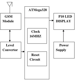
[image:2.595.22.282.233.515.2]5. Block Diagram
Figure: Digital Notice Board (IOT based).
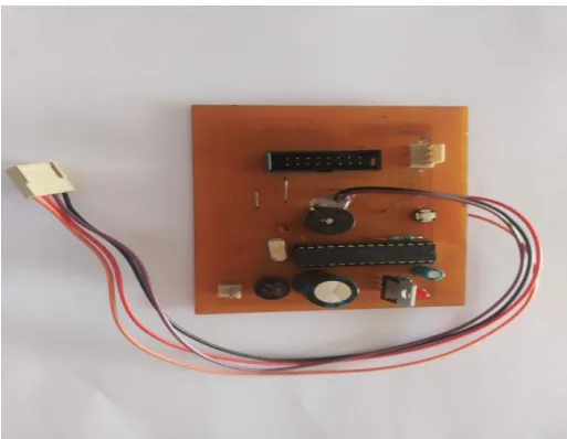
6. Hardware Details
1) Power Supply:-
It requires 5 Volts 10 Amp current. Power supply is an step down transformer. For getting +5 Volts supply we are using SMPS.
SMPS:
SMPS stands for Switched Mode Power Supply. The input to SMPS is 230 Volts ac and output is +5 Volts. A Switched mode power supply is an electronic power supply that incorporates a switching regulator to convert electrical power efficiently.
2) GSM Module:-
GSM is a mobile communication modem. It stands for Global System for Mobile communication. It is widely used in mobile communication system in world. A GSM modem is a specialized type of modem which accepts a SIM card, and operates over a subscription to a mobile operator, just like a mobile phone. GSM modem devices for both sending and receiving SMS and MMS messages. GSM is an open and digital cellular technology used for transmitting mobile voice and data services operates at the 850MHz, 900MHz, 1800MHz and 1900MHz frequency bands. GSM modem is usually preferable to a GSM mobile phone.
[image:2.595.318.542.473.667.2]
Fig. GSM Module ATMega328
GSM Module
Level Convertor
Power Supply
P10 LED DISPLAY
Clock 16MHZ
© 2019, IRJET | Impact Factor value: 7.211 | ISO 9001:2008 Certified Journal | Page 7511 2) P10 LED Display:-
This large, bright 512 LED matrix panel has
on board controller circuitry designed to make it easy to use straight from your board.Clocks,Status displays,graphic readouts and all kind of impressive display project are easy to create using this display.The distance between two points are
10mm
then it is called as P10 LED display. Pstands for
Fig. P10 LED Display
pixel and pixel stands for dot. It displays 16 rows and 32 columns total 512 led shown in one led display. P10 led display contain shift register ICs and data transfer serial in parallel out. It is tough frame material.
4) ATMega328:-
Arduino board is important in our project. ATMega328 is basically an advanced virtual RISC microcontroller. It receives the data from GSM, and gives signal to P10 LED display. Arduino is an open-source platform used for building electronic projects. It supports the data up to 8bits. ATMega328 has 32KB internal built in memory. The device operates between 1.8 to 5.5 volts. The most common implementation of this chip is on the popular Arduino development platform,
namely the Arduino Uno and Arduino Nano models.
[image:3.595.308.565.139.338.2]
Fig. ATMega328
Features:
• High performance.
• Non programmable data and program
memory.
• Low power consumption.
• Fully static operation.
• 32KB Flash memory.
• Advance RISC Architecture.
• 2kb SRAM.
5) RTC(Real Time Clock ):-
The RTC stands for Real Time Clock i.e. a Real Time Clock (RTC). This module has 56bytes
on Non-volatile memory available for use, is able
© 2019, IRJET | Impact Factor value: 7.211 | ISO 9001:2008 Certified Journal | Page 7512
case of power failure in the module.
Fig. Real Time Clock
6) Bluetooth HC05:-
HC-05 embedded Bluetooth serial communication module has two work modes: order-response work mode and automatic connection work mode. And there are three work roles (Master, Slave and Loopback) at the automatic connection work mode.
When the module is at the automatic connection work mode, it will follow the default way set lastly to transmit the data automatically. When the module is at the order-response work mode, user can send the AT command to the module to set the control parameters and sent control order.
Fig. Bluetooth HC05
7) Level Convertor:-
The logic level convertor is also called as level shifter, level translator. Level convertor is a small device that safely steps down 5 Volt signals to 3.3 Volt and step up 3.3 Volt signals to 5 Volt.
7. Working
The GSM Module used consist of a SIM Card of some number. The message transmitted by any number to this number is received and saved in the memory of the SIM card.
The module works with the AT –commands. RxD and TxD pins of this GSM module are connected to the TxD and RxD of the ATMega328 respectively so that the information or message is transmitted.
The message received by GSM module is retrieved by the ATMega328 by using suitable AT commands. The message is transferred to the display board.
8. Problem Definition
The proposed system “IOT Based Digital Notice Board” is cheap, quick reliable and secured for any organization that requires to circulate notice regularly and reduce physical efforts. We are using GSM technology so there is no problem of the range i.e. distance. We can send notice from any location. The proposed system uses SIM900, LED Display, GSM module, ATMega328. It has proposed its advantage in advertisement.
9. Conclusion and Future Scope
© 2019, IRJET | Impact Factor value: 7.211 | ISO 9001:2008 Certified Journal | Page 7513
and easy to use that interacts with the intended users instantly. The system can be used in various applications like banking, schools, restaurants, offices, hospitals, score boards for sports etc.
10. References
[1] Kruthika Simha, Shreya, Chethan Kumar,
Parinitha C, Shashidhar Tantry, “Electronics Notice Board With Multiple Output Display”,
International Conference on Signal Processing, Communication, Power and Embedded System (SCOPES)- 2016.
[2]Neeraj Khera, Divya Shukla, Shambhavi Awasthi, “Development of Simple and Low Cost Android Based Wireless Notice Board” ,International Conference on Reliability, Infocom Technology and Optimization (ICRITO) (Trends and Future Directions), Sep. 7-9-2016.
[3]Aniket Pramanik, Rishikesh, Vikash Nagar,et.al, “GSM based Smart Home and Digital Notice Board”, 2016 International Conference on Computational Technology in Information and Communication Technology (ICCTICT).
[4]Yash Teckchandani, G.Siva Perumal, Radhika Mujumdar, Sridhar Lokanathan, “Large Screen Wireless Notice Display System”, 2015 IEEE International Conference on Computational Intelligence and Computing Research.
[5]Dharmendra Kumar Sharma, Vineet Tiwari, Krishnan Kumar, et.al, “Small and Medium Range Wireless Electronics Notice Board using Bluetooth and Zig Bee ”, IEEE INDICON 2015 .
[6]Sayidul Morsalin, Abdur Rahman, et.al,
“Password Protected Multiuser Wireless
Electronic Noticing System by GSM with Robust
Algorithm”, Procedings of International
Conference on Electrical Information and Communication Technology (EICT 2015).